
SMT Turnkey Line Underperforming? A Problem-Solution Guide to Equipment Acceptance and Terms
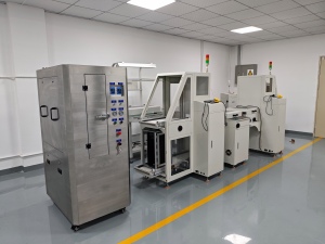
A newly installed SMT turnkey line that will not reach its promised output is usually not one broken machine. It is three questions that were never separated: does each machine meet its own specification, does the line behave as one integrated system, and what exactly did both parties agree would count as “accepted”?
This guide is written for the electronics manufacturer that has already taken delivery and is now watching throughput, yield, or stability miss the target. It works through the three failure points behind most early shortfalls on an integrated PCBA line — pick-and-place mispicks and feeder setup, reflow oven profile drift, and uneven dispensing from an automatic online glue dispenser — then shows how each one is prevented at the contract stage, before the equipment ever ships.
What “Underperforming” Actually Means
Underperformance on an SMT line is not one problem. It appears as three distinct signals, and each one points at a different layer of the line. Naming the signal correctly is the first diagnostic step, because the same phrase — “the line is not performing” — can describe a placement defect, a thermal defect, or a contract that was never specific enough to test.
- Throughput shortfall. Actual boards per hour sit below the figure in the line specification. The signal usually sits in placement, board handling, or line balancing rather than in the reflow or inspection stage.
- Quality shortfall. First-pass yield falls below target because of placement defects, insufficient or excessive solder, or adhesive-related defects. This points at process windows, not at machine speed ratings.
- Stability shortfall. The line hits target on a golden board but drifts across a shift or across a product changeover. This is the signal most often caused by an undefined acceptance process, and it is the one buyers most frequently ignore.
Only the third signal is normally a commercial problem rather than an engineering problem. It is also the most expensive, because it cannot be fixed by adjusting a parameter.
Why Early Ramp-Up Failures Cluster in High-Mix Production
The global Surface Mount Technology equipment market was valued at approximately USD 6.6 billion in 2025 and is projected to reach USD 14.6 billion by 2036, according to Transparency Market Research. Asia-Pacific dominated that market in 2025 with a 54% revenue share, followed by North America and Europe.
Within that market, placement equipment is the largest single segment, accounting for roughly 38% to 48% of total SMT equipment market value according to Persistence Market Research and Cognitive Market Research. That concentration matters commercially: the pick-and-place machine is where the largest share of line budget sits, and therefore where specification disputes concentrate during acceptance.
At the same time, the High-Mix / Low-Volume assembly segment is projected to grow at a CAGR of 8.31% through 2031, driven by demand for customized industrial and medical electronics (Mordor Intelligence). High-mix lines change over frequently, so a line that passes acceptance on one board can fail on the next one. That is the structural reason acceptance must be defined across a product family rather than on a single demonstration board.
On the quality side, IPC-A-610J, released in March 2024, is the current global standard for the acceptability of electronic assemblies and defines Class 1, Class 2, and Class 3 quality levels (IPC International). Naming the applicable class in the purchase contract is what converts a subjective “the boards look fine” into an auditable acceptance criterion. Inspection is also the fastest-growing equipment sub-sector, with 3D AOI (Automated Optical Inspection) and SPI (Solder Paste Inspection) tracking a 15.2% CAGR, largely due to automotive zero-defect requirements (Persistence Market Research) — a signal that buyers increasingly expect measurable evidence rather than visual approval.
Isolate the Root Cause Before You Blame the Machine
Three layers can each produce identical symptoms on the line. Testing them in order prevents the most common commercial mistake: opening a warranty claim against the wrong party.
- Layer 1 — Equipment. A single module fails its own specification test, repeatably, under verified inputs. Example: a mounter that cannot hold placement accuracy on a defined component at a defined sample size.
- Layer 2 — Line integration. Every module passes individually, but the line does not. The usual suspects are SMEMA handshake timing, conveyor height and transfer speed mismatch, buffer capacity, board support, exhaust routing, and feeder or nozzle interchangeability across stations.
- Layer 3 — Acceptance process. Everything passes on the supplier’s test board and nothing passes on the buyer’s production mix, because no golden board, no sample size, no Cpk requirement, and no profile record were ever agreed in writing.
Work the layers in that sequence. Jumping straight to Layer 3 when a nozzle is simply worn wastes weeks; blaming the machine when the acceptance criteria were never defined wastes months.
Failure Point 1 — Pick-and-Place Mispicks and Feeder Setup
The typical symptom set is missing components, wrong orientation, intermittent “no pick” alarms, and a placement offset that appears and disappears between runs. Operators usually report it as a machine reliability problem. In practice it splits across all three layers.
Equipment-side checks: nozzle vacuum level and nozzle condition, the nozzle replacement cycle for the specific head type in use (SMT nozzle replacement for Fuji, Yamaha and JUKI heads is a routine consumable decision, not an emergency), feeder tape advance accuracy, and the fact that 8 mm, 12 mm and 24 mm SMT feeder banks each present a different pick geometry. A feeder set that is correct for 0402 passives can behave badly when a 12 mm tape is loaded into a cart calibrated for 8 mm pitch.
Integration-side checks: feeder cart datum alignment against the machine’s pick position, PCB support pin placement under the placement area, conveyor clamping force, and board warpage after printing. These are line-level conditions, and they change the moment boards change.
Acceptance-side question: was the feeder and nozzle set for the buyer’s actual component mix included in the original scope, and was placement accuracy verified as a capability figure on the buyer’s smallest chip and its fine-pitch IC — not on a demonstration board chosen by the supplier?
For reference, the Hanwha Decan S2 pick-and-place machine used in Motek turnkey configurations is specified at 92,000 CPH (optimum, HS10 head), with a 2 gantry × 10 spindles/head structure, placement accuracy of ±28 μm Cpk≥1.0 on 03015 chip and ±25 μm Cpk≥1.0 on IC, a component range of 03015 to 12 mm with H10 mm, and a standard PCB range of 50 × 40 to 510 × 460 mm. Motek is an SMT turnkey solution supplier that builds and integrates complete PCBA lines — printing, placement, dispensing, reflow, inspection and board handling — for high-mix electronics manufacturers, with equipment exported to the EU, US, AU, CA and ASEAN markets since 2011.
Those placement figures are acceptance-testable. Each one can be reproduced with a documented test board, a defined sample size, and a stated Cpk requirement. Where disputes usually begin is when the line was ordered for a component mix, verified on a simpler board, and then measured against production boards that were never part of the agreement.
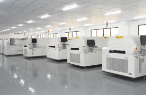
Failure Point 2 — Reflow Oven Profile Drift
Reflow profile drift looks like a thermal problem and is usually reported as one. Early boards pass, later boards show cold joints, tombstoning, warpage, or inconsistent wetting. The profile displayed on the machine looks correct while the actual board profile has moved.
Equipment-side checks: heating zone control stability, thermocouple placement and calibration, conveyor speed stability through the tunnel, cooling zone performance, and heater age. A profile is only as stable as the conveyor speed that carries the board through it.
Integration-side checks: exhaust ducting as actually installed on site, factory ambient airflow across the oven inlet, and line speed balanced against upstream and downstream stations. Exhaust performance is one of the most common on-site causes of otherwise unexplained profile drift, because the oven was validated in a different building with different ducting.
Acceptance-side question: was the thermal profile validated with a profiler on the buyer’s own board, at production conveyor speed, with the results recorded and re-validated after installation? A profile validated only at the supplier’s factory is a reference point, not an acceptance record.
The XMR-800D SMT reflow oven, supplied in Motek turnkey line configurations, uses top 8 / bottom 8 heating zones over a 3110 mm heating zone length, top 3 / bottom 3 cooling zones, a small-circulation rectifying plate structure, an exhaust volume requirement of 11 m³/min × 2, a machine weight of approximately 2710 kg, and overall dimensions of 5520 × 1430 × 1530 mm. Those figures define the utility envelope: if the installed exhaust cannot deliver the required volume, the oven is being asked to hold a profile it was not specified to hold.
Failure Point 3 — Uneven Dispensing from an Automatic Online Glue Dispenser
An online glue dispenser sits between placement and reflow, so its failures are routinely misdiagnosed as placement failures or reflow failures. The symptom is adhesive dots that vary in diameter or height across a panel, pads that receive no adhesive at all, and components that shift or drop during handling before the oven.
Equipment-side checks: dispensing valve stability, dot program accuracy after manual teaching, platform flatness, and motion control repeatability.
Integration-side checks: PCB transfer height alignment with the rest of the line, PCB width range against the actual panel, transport speed and direction consistency, and board support under the dispensing path. Transfer height is a specific and frequently overlooked variable: the HMH830D automatic online glue dispenser is specified with a PCB transfer height of 920 ± 20 mm, a PCB width range of 50–450 mm, a transport speed of 0–5000 mm/min, L→R (R→L) transfer direction, two stepper transmission motors, an industrial computer with motion control card, manual teaching programming with storage for more than 1,000 running programs, a T20 mm steel plate chrome plated equipment platform, a weight of 650 kg, and an overall size of L1060 × W1200 × H1700 mm.
Acceptance-side question: was dispensing uniformity measured across the full PCB width, or only at the center of the panel? A single measurement point cannot detect a flatness or height-alignment problem, which is exactly the class of defect that shows up later as inconsistent component retention.
The Five Documents That Decide Whether the Line Ramps
Buyers who report clean ramp-ups tend to have the same five documents in place before shipment. None of them is exotic; all of them convert verbal assurances into testable criteria.
- Line capability specification sheet. One row per module, one column per testable parameter. It should name every station in the line: solder paste printer, pick-and-place machine, automatic online glue dispenser, SMT reflow oven, AOI automatic optical inspection, inline SPI inspection machine, X-ray BGA inspection machine, PCB loader and unloader, SMT buffer conveyor, PCB depaneling router, PCBA cleaning machine, and stencil cleaning machine.
- FAT protocol with a golden board. The factory acceptance test must define the board, the sample size, the pass criteria, and the measurement method — not just the result.
- Utility and interface matrix. Power, compressed air, exhaust volume, SMEMA handshake, conveyor heights, and floor space, documented against the site that will actually run the line.
- Consumables and spare parts list. SMT nozzle replacement sets for the specific head types in use, 8 mm / 12 mm / 24 mm SMT feeder allocations, valves, belts, and the associated lead times and supply responsibility.
- Ramp-up and acceptance schedule tied to payment milestones. Pre-shipment verification, installation, on-site re-test, trial production across the product family, and final sign-off, each attached to a payment stage.
A Practical Acceptance Sequence, Step by Step
- Freeze the product family before ordering. Select the hardest board in the family — smallest components, densest placement, tightest thermal mass — and use it as the reference for the whole acceptance process.
- Run the factory acceptance test at the supplier. Capability run on the golden board, with documented Cpk, plus the buyer’s board if logistics allow.
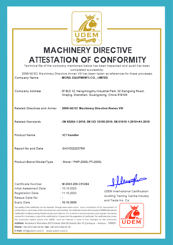
- Assemble the compliance pack. For Motek-supplied lines this includes the ISO 9001:2015 certificate HIC210707 (issued 12 July 2021, valid to 10 July 2028), covering the sales of Pick & Place machines and their accessories, Solder Paste Printer, and mechanical equipment; the Machinery Directive Attestation of Conformity M.2023.206.C91284 under 2006/42/EC Annex VIII with EN 60204-1:2018, EN ISO 12100:2010 and EN 61010-1:2010+A1:2019; and the German Packaging Act registration DE2364478064729 under VerpackG § 9 and § 26.
- Confirm pre-shipment conditions in writing. Pre-shipment testing, configuration list, and shipping schedule — standard lead time is 7–45 days depending on configuration, with a minimum order quantity of one unit.
- Verify utilities on site before the equipment arrives. Exhaust capacity, power, air, and floor layout against the utility matrix, not against the quotation brochure.
- Re-run the FAT protocol after installation. The same boards, the same sample size, the same pass criteria. This is the step that separates an equipment problem from an installation problem.
- Run trial production across the family. Change over between at least three products and record changeover time, first-pass yield, and stability across a full shift.
- Sign off formally and release the final payment stage. Acceptance should be a dated, signed event with attached measurement records — not a conversation at the end of installation week.
What a Correctly Ramped Line Looks Like
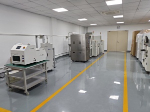
The outcome of a defined acceptance process is not a perfect installation — it is a line whose performance is predictable. Motek turnkey engagements with SMT factory customers in Germany, Israel, India and Australia involved 20–35 units per project, with installations running for five years across applications including smartphone motherboard assembly, tablet computer circuit board production, ECU control unit assembly, LED display modules, LED streetlight drivers, and consumer electronics smartphone PCB assembly at 50,000 units per month. The reported production result is a mass production range of 20,000–100,000 pieces per day.
Read that case in acceptance terms rather than sales terms. The output is expressed as a mass-production range, not a peak rating, and it is tied to a defined set of applications rather than to a generic board. That is exactly how the capability sheet should be written before the purchase order is signed.
Comparison: Symptom, Root Cause Layer, and the Evidence That Prevents It
| Observed symptom | Most likely layer | Acceptance evidence that prevents it |
|---|---|---|
| Missing components, wrong orientation, intermittent no-pick alarms | Equipment (nozzle, feeder) or integration (feeder cart datum, board support) | Placement accuracy recorded as Cpk on the buyer’s smallest chip and fine-pitch IC; feeder and nozzle set defined against the actual component mix |
| Placement offset that appears and disappears between runs | Integration (clamping, support pins, warpage) or acceptance (no defined sample size) | Documented pick-position teach procedure and repeatability test across a full shift |
| Cold joints, tombstoning, warpage appearing later in the run | Integration (exhaust, ambient airflow, line speed) before equipment | Profiler-verified thermal profile on the buyer’s board at production speed, re-validated on site after installation |
| Adhesive dots varying across the panel | Equipment (valve, teaching) or integration (transfer height, platform alignment) | Dispensing uniformity measured across the full PCB width, with transfer height and transport speed recorded |
| Line passes on the golden board, fails on production mix | Acceptance process | Product-family definition frozen before ordering; trial production across at least three products before sign-off |
Module-Level Verification Reference
The table below maps each station in a turnkey PCBA line to the verification point that should appear in the acceptance protocol. Where a specific model is listed, the parameters are the published specification of that model and can be tested directly.
| Line module | What to verify at acceptance | Reference specification where applicable |
|---|---|---|
| Solder paste printer | Paste deposit consistency against stencil aperture; print repeatability; stencil cleaning cycle | Covered in the ISO 9001:2015 scope of the supplier’s certification |
| Pick-and-place machine | Placement accuracy as Cpk on defined components; throughput at specified head configuration; component and PCB envelope | Hanwha Decan S2: 92,000 CPH optimum (HS10 head); ±28 μm Cpk≥1.0 on 03015 chip; ±25 μm Cpk≥1.0 on IC; 03015–12 mm, H10 mm; PCB 50 × 40 to 510 × 460 mm |
| Automatic online glue dispenser | Dot uniformity across the full PCB width; transfer height alignment; program repeatability | HMH830D: PCB width 50–450 mm; transfer height 920 ± 20 mm; transport speed 0–5000 mm/min; more than 1,000 stored programs |
| SMT reflow oven | Thermal profile repeatability at production speed; zone control stability; installed exhaust volume | XMR-800D: top 8 / bottom 8 heating zones; 3110 mm heating length; top 3 / bottom 3 cooling zones; exhaust 11 m³/min × 2 |
| AOI, inline SPI, X-ray BGA inspection | False-call rate, program library coverage, defect escape rate against the agreed IPC-A-610J class | Acceptability class must be named in the contract (IPC-A-610J Class 1, 2 or 3) |
| Loader / unloader, buffer conveyor, depaneling router, cleaning stations | SMEMA handshake timing, transfer height match, board damage check | Interface and utility matrix agreed before shipment |
Frequently Asked Questions
1. Which compliance documents should be attached to an SMT turnkey contract?
Two categories. First, the acceptability class: name the applicable IPC-A-610J level (Class 1, 2 or 3), released in March 2024, so that board-level acceptance is auditable rather than visual. Second, machine-level conformity evidence. For Motek-supplied equipment this includes the Quality Management System certificate HIC210707 under ISO 9001:2015 / GB/T 19001-2016 (issued 12 July 2021, valid to 10 July 2028, scope covering sales of Pick & Place machines and accessories, Solder Paste Printer, and mechanical equipment), the Machinery Directive Attestation of Conformity M.2023.206.C91284 (UDEM, issued 11 October 2023, valid to 10 October 2028, referencing 2006/42/EC Annex VIII, EN 60204-1:2018, EN ISO 12100:2010 and EN 61010-1:2010+A1:2019), and the German Packaging Act registration DE2364478064729 with the ZSVR under VerpackG § 9 and § 26.
2. How can we verify pick-and-place accuracy and throughput before the line ships?
Require capability figures rather than peak figures. A verifiable acceptance test states the component, the sample size, and the Cpk. The Hanwha Decan S2 used in Motek turnkey lines is specified at 92,000 CPH optimum with the HS10 head, 2 gantry × 10 spindles/head, ±28 μm Cpk≥1.0 on a 03015 chip and ±25 μm Cpk≥1.0 on an IC, with a component range of 03015 to 12 mm at H10 mm and a standard PCB range of 50 × 40 to 510 × 460 mm. Each of these can be re-measured on site using the same protocol.
3. What does it cost to leave acceptance undefined?
An undefined acceptance process shifts cost into the ramp-up phase rather than the purchase phase: repeat installation work, emergency consumables, unplanned line idling, and disputed responsibility between the equipment supplier and the integrator. The controllable variables are commercial and known in advance — standard lead time runs 7–45 days depending on configuration, and the minimum order quantity is one unit, so a specification discussion before shipment does not require a larger order to protect the schedule.
4. Can we validate the line with our own boards before final acceptance?
Yes, and it is the single most effective protection against a ramp-up dispute. The protocol should combine a golden board with the buyer’s own production boards, and it should be re-run after installation rather than only at the supplier’s facility. Motek supports this through remote technical support, 24/7 online service, and the option for customer engineers to attend training at the factory in China for approximately one week, so the people who will sign off on acceptance are the same people who understand the test method.
5. What is a realistic timeline from purchase order to a ramped line?
Lead time is 7–45 days depending on configuration, and that is only the first segment. A realistic plan adds installation, the on-site re-run of the factory acceptance test, and trial production across the product family before formal sign-off. Building the payment milestones around those four stages is what keeps the schedule visible. To start the process with your own board data, request a sample evaluation or a configuration quotation and attach your component mix and panel dimensions.
Conclusion: Define Acceptance Before You Define Blame
When an SMT turnkey line underperforms after installation, the productive question is not “which machine is faulty” but “which layer failed”: the equipment, the line integration, or the acceptance process that was never written down. Mispicks and feeder setup usually resolve to a nozzle, feeder or cart-datum condition. Reflow profile drift usually resolves to exhaust, ambient airflow or line speed rather than to the heating zones. Uneven dispensing from an automatic online glue dispenser usually resolves to transfer height, platform alignment or a measurement taken only at the center of the panel. And when the line passes on the golden board but fails on the production mix, the root cause is almost always a contract that did not define the product family, the sample size, or the Cpk.
The fix is not technical improvisation after delivery. It is five documents, eight acceptance steps, and a payment schedule that treats sign-off as a measurement event. That combination is what turns a turnkey purchase into a predictable production line — and it costs nothing to add before the purchase order is issued.
Next Step: Validate the Line Against Your Own Boards
Send your component mix, panel dimensions, and target output. We will map them against the placement, dispensing, reflow and inspection configuration of a Motek SMT turnkey line and return an acceptance protocol you can attach to the purchase terms.
Email: sales@morequip.com | Tel: +86-755-21635007 | WhatsApp: +86 199 2455 0176
Address: Guangdong Shenzhen Baoan 405, Block A, Building 6, Exhibition Bay Zhonggang Plaza, No. 83 Zhancheng Road, Zhancheng Community, Fuhai Street
Have Questions or Need More Details?
Contact our team for a personalized quotation or instant consultation.
Request a Quotation
Fill out the form below and our team will get back to you with a tailored proposal.
WhatsApp Direct Chat
Prefer to chat in real-time? Message us on WhatsApp for instant assistance & quick answers.
- Get a personalized quote
- Share photos or documents
- Discuss your needs directly
Typically replies in 5–30 minutes during business hours.