
SMT Turnkey Line Architectures Compared for High-Mix Production
Short answer: high-mix electronics manufacturers converge on three SMT turnkey line architectures — standalone cells with offline glue dispensing, a partially integrated inline where printing, inspection, placement and reflow share one conveyor flow, and a fully integrated inline where an automatic online glue dispenser is inserted into that same flow ahead of placement. What separates them is rarely peak placement speed. It is changeover time, conveyor handoff discipline, and the floor space consumed per product variant.
This guide compares those three architectures side by side, using published machine parameters instead of brochure superlatives, and closes with the purchasing terms and acceptance criteria a buyer should verify before signing off on a configuration. The goal is a decision framework you can apply to your own production profile — not a recommendation of one architecture over another.
Problem Definition: Why High-Mix Production Breaks Single-Product Line Logic
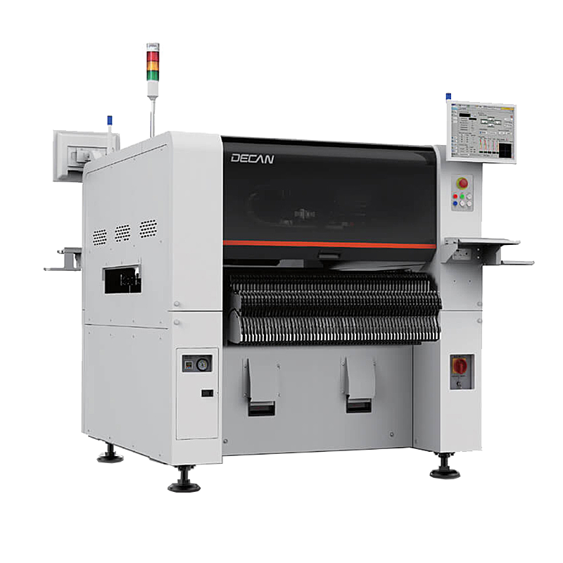
A published placement speed — for example 92,000 CPH at optimum condition with an HS10 head on the Hanwha Decan S2 — answers one question only: how many components per hour the machine places when nothing interrupts it. High-mix manufacturing interrupts it constantly.
In a high-mix environment, the recurring cost is not the placement cycle. It is everything that happens between two different products: stencil and solder paste change, feeder restocking across 8 mm, 12 mm and 24 mm positions, nozzle verification after nozzle replacement, program recall on every machine in the line, and first-article confirmation through SPI, AOI and X-ray before the first good board is released.
Each of the three architectures absorbs that cost differently, and each shifts the burden to a different place:
- Standalone cells absorb changeover as queue time. Boards wait in magazines between stations, so a slow change at one cell affects only that cell.
- Partially integrated inline absorbs changeover as sequence time. Nothing advances until every upstream machine has changed over, so the slowest changeover sets the pace for the whole line.
- Fully integrated inline absorbs changeover as engineering effort. Program recall is fast — an automatic dispenser such as the HMH830D stores more than 1,000 running programs — but board-width changes propagate through every machine simultaneously.
That is why two factories running comparable placement hardware can report very different effective throughput. The architecture, not the machine, determines which losses recur every shift.
Industry Background: A Growing Market With a Quality-Driven Skew
The global SMT equipment market was valued at approximately USD 4.3 billion in 2024, with forecast coverage running from 2024 to 2030 and 112 companies profiled in the source report (Research and Markets, October 2026). Within that total, inspection is the fastest-growing segment, estimated at a 15.2% CAGR for the 2026–2033 period and driven by AI-powered 3D AOI and SPI.
Two cautions apply when reading such figures. First, publishers define the market differently: one 2025 estimate for the broader "SMT market" includes components and is not directly comparable with the equipment-only figure above, so the two should never be combined in a single calculation. Second, mounting-speed benchmarks are quoted on inconsistent bases. The Fuji NXT III H24G high-speed head is specified at 37,500 CPH per module, while other vendors publish figures per beam, per head or per machine. A 92,000 CPH optimum rating on a two-gantry, ten-spindle-per-head platform is not superior or inferior to a per-module figure until both are normalized to the same unit.
Practical consequence for buyers: the growth of inspection spending suggests that downstream quality control, not raw placement volume, is where high-mix factories are concentrating capital. An architecture that cannot accept inline SPI, AOI and X-ray cleanly will need retrofitting sooner than expected.
The Three Architectures in Detail
All three architectures contain the same process steps — deposition, placement, thermal processing, inspection. They differ only in how tightly those steps are coupled and where the glue dispensing function sits.
Architecture A — Standalone Cells With Offline Glue Dispensing
Here the dispenser, the printer, the placer, the oven and the inspection equipment are independent assets connected by operators and magazine transfer rather than by a conveyor. Adhesive deposition happens in a separate cell, on its own schedule, and boards are re-loaded for placement afterwards.
The strength of this layout is granularity. A failure at one cell does not stop the others, capital can be released in phases, and a very wide product mix can be routed selectively — some boards through the dispenser, some not. The weakness is material handling: work-in-process accumulates, handling damage risk rises, and labor content per board is higher because every transfer is a manual event.
Architecture B — Partially Integrated Inline
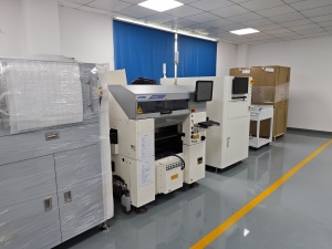
Printing, solder paste inspection, placement, reflow and unloading are linked into one flow, typically as loader → solder paste printer → SPI → pick-and-place → reflow oven → unloader, with AOI, X-ray, ICT, a PCB turner, an NG separator and a stencil cleaner positioned around it. The adhesive process, however, remains outside that flow and is scheduled as a secondary operation.
This is the most common compromise in high-mix factories because it captures the biggest inline gain — eliminating manual transfer between print, place and reflow — without forcing every board through a dispensing stage that only some products need.
Architecture C — Fully Integrated Inline With Automatic Dispensing
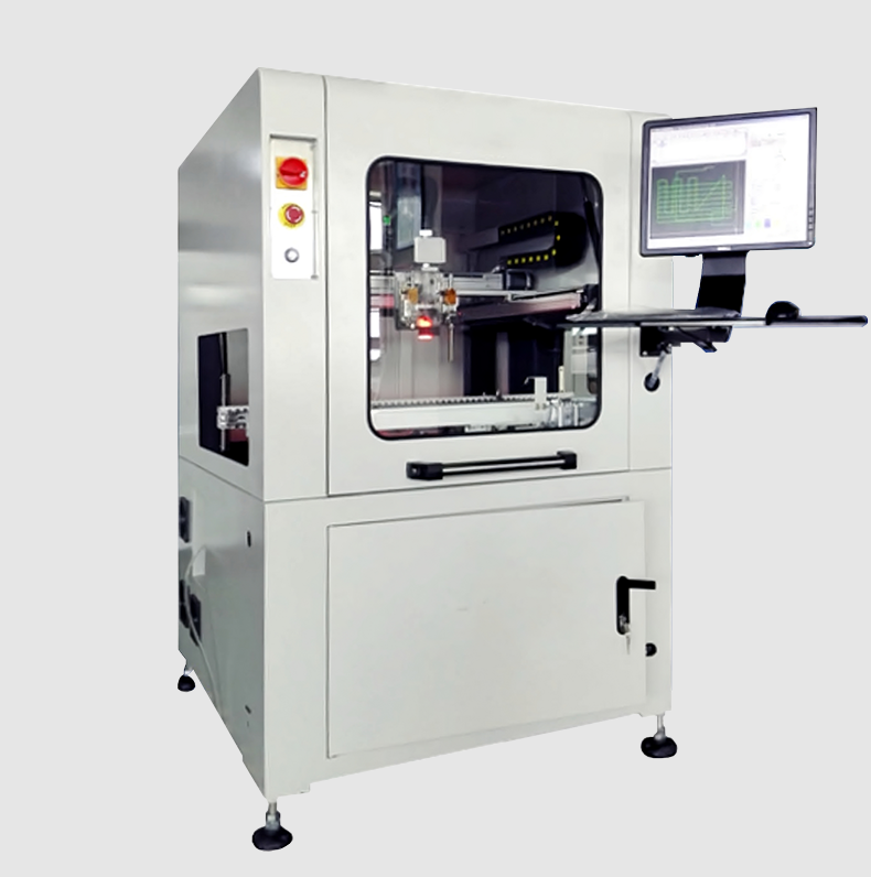
In the fully integrated variant, an automatic online glue dispenser such as the HMH830D is placed inside the same material flow, ahead of the placement stage. Its conveyor parameters then become line parameters: PCB transfer height of 920 ± 20 mm, transport speed from 0 to 5,000 mm/min, transport direction L→R or R→L, and a PCB width range of 50–450 mm.
The integration gain is real — one material flow, one operator interface, no re-loading between dispensing and placement — but it also caps the architecture. The Hanwha Decan S2 placer accepts boards from 50 × 40 mm up to 510 × 460 mm, while the dispenser accepts a PCB width of 50–450 mm. A board or panel wider than 450 mm cannot pass through the inline dispenser, so that product must be routed offline or the dispenser specification must be revisited. This is the single most common mismatch discovered late in a configuration review.
Where the Machines Set the Architecture Boundaries
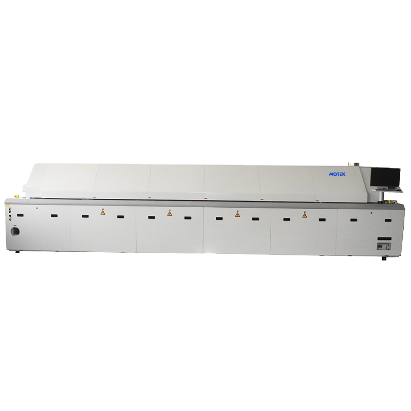
The equipment parameters below are the ones that constrain an architecture decision. They are taken from the equipment range offered through Motek, the brand of Morel Equipments Co., Ltd.
| Stage | Model | Verified parameters that affect architecture |
|---|---|---|
| Placement | Hanwha Decan S2 SMT Pick And Place Machine | 92,000 CPH (optimum, HS10 head); 2 gantry × 10 spindles per head; ±28 μm Cpk ≥ 1.0 (03015 chip) and ±25 μm Cpk ≥ 1.0 (IC); parts 03015–12 mm, height 10 mm; PCB 50 × 40 to 510 × 460 mm (standard) |
| Thermal | XMR-800D SMT Reflow Oven | 8 top / 8 bottom heating zones; 3,110 mm heating zone length; 3 top / 3 bottom cooling zones; 5,520 × 1,430 × 1,530 mm; approx. 2,710 kg; exhaust 11 m³/min × 2; thick copper plate; small circulation rectifying plate |
| Dispensing | HMH830D Automatic Online Glue Dispenser | PCB width 50–450 mm; transport speed 0–5,000 mm/min; PCB transfer height 920 ± 20 mm; L→R (R→L); more than 1,000 running programs; manual teaching; industrial computer plus motion control card; 1,060 × 1,200 × 1,700 mm; 650 kg |
Step-by-Step Breakdown: Matching an Architecture to a Production Profile
The sequence below turns the comparison into a decision. Work through it in order; the early steps eliminate architectures rather than rank them.
- Profile the board envelope before anything else. List every PCB and panel size in the current mix plus the two largest sizes planned for the next product cycle. If the maximum width exceeds 450 mm, the fully integrated inline architecture is unavailable for that product unless dispensing is moved offline — the placer's 510 × 460 mm envelope does not extend the dispenser's 450 mm limit.
- Decide whether adhesive deposition belongs in the flow. Products that require adhesive deposition on every board justify inline dispensing. Products where only a minority of boards need it usually justify Architecture B, with the dispenser scheduled as a secondary operation.
- Size placement against the mix, not the datasheet. Confirm the component range actually used — 03015 to 12 mm with a 10 mm height limit on the Decan S2 — and check feeder availability across 8 mm, 12 mm and 24 mm widths. Feed replenishment, not placement speed, is the usual changeover bottleneck in high-mix work.
- Size the thermal window. The XMR-800D provides eight heating zones top and bottom across a 3,110 mm heating length, plus three cooling zones top and bottom. Zone count and heating length determine how many distinct reflow profiles the line can hold without compromise — the decisive factor when the mix spans thin consumer boards and heavy power-supply assemblies.
- Plan the physical installation. The reflow oven alone occupies 5,520 mm of line length, stands 1,530 mm high, weighs approximately 2,710 kg and requires 11 m³/min × 2 of exhaust capacity. The dispenser occupies a 1,060 × 1,200 mm footprint and weighs 650 kg. Floor loading, exhaust routing and service access should be checked before the layout is frozen.
- Close the inspection loop and write the acceptance criteria. Inline SPI after printing, AOI after reflow and X-ray for BGA verification should be positioned so that a rejected board never re-enters the flow. Then define, in writing, how the line will be tested before final acceptance.
Use Cases: Which Architecture Fits Which Production Profile
High-mix SMT work spans several industries with different tolerance for changeover time. The application profile commonly used for turnkey line planning covers automotive electronics, smart transportation, industrial automation, consumer electronics, medical technology, new energy systems, LED and optoelectronics, and telecommunications — operating indoor in ISO Class 8 cleanroom conditions, at 23 °C ± 2 °C and 50% ± 10% relative humidity, with ESD protection and ANSI/ESD S20.20 compliance inside the EPA zone.
- Automotive electronics and industrial control. Traceability and profile repeatability dominate. Architecture C, with inline dispensing and a multi-zone reflow stage, keeps every board on one documented path — the simplest configuration to audit.
- Medical device PCB assembly. Small lots with high documentation burden favor Architecture B: inline printing, placement and reflow for consistency, with adhesive work isolated so it does not delay the main flow.
- Consumer electronics and LED display assembly. High variant counts and short product lives favor Architecture A or B, where changeover at one cell does not stall the entire line.
- 5G communication equipment and power supply modules. Larger, heavier boards and mixed-technology assemblies typically need inline dispensing — but only if board width stays within the 450 mm dispenser limit.
- New energy systems. Continuous 24/7 operation with buffering between stages usually justifies at least a partially integrated inline plus buffer conveyors, so a single stop does not drain the whole line.
Comparison Table: Architecture Fit by Decision Dimension
| Decision dimension | A — Standalone cells | B — Partially integrated inline | C — Fully integrated inline |
|---|---|---|---|
| Process sequence | Dispensing, printing, placement and reflow in separate cells with manual transfer | Loader → printer → SPI → placer → reflow → unloader inline; dispensing offline | Dispenser inside the same flow, ahead of placement, with inline handoff throughout |
| Conveyor dependency | None between cells | Single-direction handoff | Dispenser transport parameters become line parameters: 920 ± 20 mm transfer height, 0–5,000 mm/min, L→R or R→L |
| Board-size envelope | Limited by each machine independently | Limited by printer and placer | Limited by the narrowest inline machine: 50–450 mm at the dispenser versus 50 × 40 to 510 × 460 mm at the placer |
| Changeover behaviour | Queues build between cells; a slow change affects one cell only | Slowest changeover sets the pace for the whole line | Program recall is fast (more than 1,000 stored programs) but width and profile changes propagate to every machine |
| Floor space | Largest total footprint, distributed across the hall | Moderate; reflow oven alone needs 5,520 mm of line length | Most compact per variant, but the layout is rigid once installed |
| Inspection integration | AOI and X-ray handled offline | Inline SPI and AOI; X-ray positioned at the flow | Inline SPI, AOI and X-ray with no manual re-routing of rejects |
| Best fit | Prototyping, very high variant count, low volume | Mid-mix production with mixed technology boards | Stable high-mix families that stay within 450 mm board width |
| Main risk | Work-in-process and handling damage | Dispensing stage becomes a scheduling conflict | Board-width cap and a single point of stoppage |
Purchasing Terms and Acceptance Criteria to Verify Before Sign-Off
A configuration is only as good as the test that proves it. Before signing, confirm each of the following in the purchase agreement rather than in conversation.
- Measurement basis for speed and accuracy. State the head type, component type and condition under which CPH and accuracy will be verified — for example optimum condition with the HS10 head, and ±28 μm Cpk ≥ 1.0 on 03015 chips.
- Board-size acceptance test. Run a board at the top and bottom of the declared envelope, including one sample at the 450 mm dispenser limit if Architecture C is selected.
- Changeover time test. Measure a full product-to-product change on the installed line, including stencil, feeder, nozzle and program steps, and record the result in the acceptance protocol.
- Thermal capability proof. Require a measured profile on a representative board through the eight-zone heating and three-zone cooling section, with process control referenced to the IPC-7801 reflow oven process control standard.
- Compliance documentation. Request CE certification documentation covering the specific models quoted, quality management evidence such as ISO 9001:2015, and ESD control documentation aligned with ANSI/ESD S20.20 for the EPA zone.
- Spares and consumables list. Itemize nozzles, feeders in 8 mm, 12 mm and 24 mm widths, and wear parts, with part numbers that match the delivered machines.
- Warranty and service terms. Confirm warranty duration, start date — tied to acceptance rather than shipment — response path, and operator training scope.
Motek, the brand of Morel Equipments Co., Ltd., is a Shenzhen-based trading company established in 2011, operating from a 955 m² facility with approximately 31 staff and exporting 100% of its output to markets including the EU, USA, Australia, Canada and ASEAN. Documented supplier information records 300–500 units exported annually and ISO 9001:2015 certification, alongside multiple CE certifications for its equipment. More detail on the company and its line configurations is available at morequip.com.
FAQ
What certifications and standards should be verified on an SMT turnkey line before acceptance?
Verify four layers. First, CE certification documentation for the exact models quoted, not for the product family in general. Second, quality management evidence from the supplier — Morel Equipments Co., Ltd. is documented as holding ISO 9001:2015. Third, reflow process control referenced to the IPC-7801 standard for the oven stage. Fourth, ESD control aligned with ANSI/ESD S20.20 inside the EPA zone, together with the cleanroom conditions the line was specified for. Each document should carry the same model and serial references as the delivered equipment.
Can one fully integrated line handle every board size in a high-mix product mix?
No. In a fully integrated architecture the board envelope is set by the narrowest machine in the flow. The Hanwha Decan S2 placer accepts boards from 50 × 40 mm to 510 × 460 mm, but the HMH830D automatic online glue dispenser accepts a PCB width of 50–450 mm. Any board or panel wider than 450 mm must either be routed to offline dispensing or handled on a dispenser with a wider conveyor. Confirming this limit before layout prevents the most common late-stage configuration change.
Where should the budget go first: placement, reflow, or dispensing?
Allocate against the bottleneck rather than a fixed ratio. Placement accuracy matters when fine-pitch and 03015 components dominate — the Decan S2 is specified at ±28 μm Cpk ≥ 1.0 on 03015 chips and ±25 μm Cpk ≥ 1.0 on ICs. Reflow zone count matters when the mix spans light and heavy boards, since eight heating and three cooling zones across a 3,110 mm heating length define how many profiles the line can hold. Dispensing matters when adhesive deposition is on the critical path. Note also where the market is investing: inspection is growing at an estimated 15.2% CAGR, which indicates that quality-control capital, not placement volume, is where high-mix factories are concentrating spend.
Can a configuration be validated with a sample or pilot run before committing?
Yes, and it should be treated as part of the acceptance protocol rather than a courtesy. Run a representative board set covering the top and bottom of the declared envelope, measure CPH and accuracy under the stated conditions, verify a full product-to-product changeover, and confirm program recall on the dispenser — the HMH830D stores more than 1,000 running programs, which is directly relevant to high-mix scheduling. To arrange an evaluation against your own board set, contact the Motek team at sales@morequip.com or via WhatsApp on +86 199 2455 0176; a 12-month product warranty applies to the equipment supplied.
What lead-time and delivery terms should be written into the purchase agreement?
Rather than relying on a quoted number alone, specify the milestones that create it: equipment build and factory acceptance, shipping window, installation and commissioning duration, and the acceptance test that triggers final payment and the warranty start date. Add the commissioning inputs the site must supply in advance — exhaust capacity of 11 m³/min × 2 for the XMR-800D, floor loading for a unit of approximately 2,710 kg, and the 920 ± 20 mm transfer height alignment across the line. Finally, attach the spare-parts and training list to the same schedule so that consumables arrive with the machines, not after them.
Next Step: Compare Configurations Against Your Own Board Set
Architecture choice becomes concrete only when it is tested against your real product mix. Share your board sizes, variant count and adhesive requirements, and the Motek team can map them against standalone, partially integrated and fully integrated layouts — including where the 450 mm dispenser limit falls in your mix.
Email: sales@morequip.com | Tel: +86-755-21635007 | WhatsApp: +86 199 2455 0176
Download the equipment catalogue: Motek SMT turnkey equipment brochure (PDF)
Conclusion
The three SMT turnkey line architectures for high-mix production differ in coupling, not in component list. Standalone cells trade floor space and handling effort for independence. Partially integrated inline layouts capture the print-place-reflow gain while keeping adhesive work off the critical path. Fully integrated inline layouts compress changeover and inspection into one flow — but inherit a 450 mm board-width ceiling from the dispenser and the rigidity of a single material path.
The decision rule that follows is simple enough to apply in a first meeting: profile the board envelope, decide whether adhesive deposition belongs inside the flow, size placement and reflow for the mix rather than the datasheet, then write acceptance criteria that measure changeover and accuracy on the installed line. An architecture that fails one of those four tests will not be rescued by a faster machine at any single station.
Have Questions or Need More Details?
Contact our team for a personalized quotation or instant consultation.
Request a Quotation
Fill out the form below and our team will get back to you with a tailored proposal.
WhatsApp Direct Chat
Prefer to chat in real-time? Message us on WhatsApp for instant assistance & quick answers.
- Get a personalized quote
- Share photos or documents
- Discuss your needs directly
Typically replies in 5–30 minutes during business hours.