
From 5G Backhaul to Data Center Rack: Optical Fiber Cable & MPO/MTP Deployment
From 5G Backhaul to Data Center Rack: Optical Fiber Cable & MPO/MTP Deployment
A project that runs from a 5G backhaul route into a data center hall crosses three physical-layer environments before the first link is accepted: an outdoor cable route, a high-density cabinet row, and a commissioning bench. Each environment loads the same link differently, and in most organisations each is bought from a different part of a supplier's catalogue — cable by the outside-plant team, assemblies by the data center team, test modules by whoever signs the acceptance report.
This guide treats those purchases as one deployment sequence and maps three product families to the environments they are specified for:
- GYTA53 optical fiber cable for metropolitan backbone and 5G backhaul routes, where armouring, water sealing and tensile rating decide whether the cable survives installation.
- MTP/MPO fan-out pre-terminated cables for 40G/100G/400G SR4/PSM4 module connections between cabinets, where the loss budget accumulates at every mated pair.
- MPO/MTP loopbacks for data center commissioning and equipment validation, where the test tool's own insertion loss becomes part of the measurement.
Each scenario below states the design condition, the attribute that is verified on the datasheet, and the acceptance step that closes the deployment. Where a value is model-specific — attenuation in dB/km, tensile strength, minimum bend radius — the guide says so rather than assuming a number, because those figures have to be read from the datasheet of the exact model being supplied.
Why the deployment environment, not the product category, sets the specification
Three conditions separate a backhaul route from a cabinet row, and each one stresses a different part of the link.
Route exposure. Outdoor cable in this category is installed on aerial and self-supporting spans, in ducts and ducting, by direct burial, and in harsh outdoor conditions that require weatherproofing, waterproofing, rodent protection and temperature resistance. That combination drives an armoured construction with a sealed outer sheath and a defined tensile and crush capability. A cable that performs perfectly on a laboratory reel can still fail a pull through a duct bend if its tensile rating and minimum bend radius were never matched to the installation method.
Indoor density. Inside a data center the constraint moves from mechanical survival to optical margin. Dozens of mated pairs may sit between an active port and the far end, and each pair contributes insertion loss. Flame-retardant or LSZH sheath behaviour, bend radius inside a cabinet, and the grade of every adapter become the deciding variables. The product families in this category are specified with exactly those requirements in mind: low attenuation, low insertion loss, flame-retardant or LSZH sheaths, and customizable core counts and labelling.
Measurement conditions. A commissioning bench is not a passive route. Test modules are mated and unmated repeatedly, so mating-cycle endurance and return loss matter as much as insertion loss, and the test tool's own loss has to be understood before its results can be trusted.
The practical consequence is that a single "high specification" component does not fix a project. The route determines the cable construction; the cabinet determines the assembly and adapter grade; the commissioning plan determines the test module and the pass/fail threshold.
What is changing at the physical layer in 5G backhaul and data centers
The scale of the installed base is the background to every deployment decision. The global fiber optic cable market was valued at USD 14.6 billion in 2025 according to Global Market Insights, a commercial research estimate that also publishes a 2026–2035 forecast; the figure describes market size, not the demand for any single product family. Trade data tells a similar story about concentration: the Observatory of Economic Complexity, using UN Comtrade data, reports China as the leading exporter of optical fibres and cables in 2024, with exports of USD 2.52 billion under HS 854470.
On the standards side, the direction is toward environment-specific documents rather than one general cable specification. ITU-T L.103 (08/2024) describes characteristics, construction and test methods for optical fibre cables for indoor applications. IEC 60794-1-104:2024 defines the test procedure used to establish uniform requirements for impact performance. IEC 60092-378:2024 covers optical fibre cables for shipboard and offshore fixed installations — a useful reminder that the standards family is segmented by environment, and that a document written for one installation condition is not interchangeable with another.
Two practical notes follow from this. First, standards define test methods and characteristics; they do not by themselves certify a product, so a project should ask for product-level test reports and the model datasheet in addition to a standards reference. Second, for projects with a North American destination, landed-cost planning has to include duty: a customs brokerage source reports a total U.S. import duty of 37.50% on Chinese-origin optical fiber cable under HTS 8544.70.00 as of late 2026. That figure is commercial, not technical, and should be confirmed with the importer's broker before it is written into a budget.
Product-to-environment map
The table below is the working map for the rest of this guide. It pairs each environment with the product family specified for it, the attribute that decides acceptance, and the step that verifies it on site.
| Environment | Product family | Decisive verified attribute | Acceptance step |
|---|---|---|---|
| Metropolitan backbone and 5G backhaul route | GYTA53 outdoor optical fiber cable | Fiber type (G.652/G.657), attenuation in dB/km, tensile strength, minimum bend radius, sheath and environmental rating | Post-installation attenuation test per span against the model datasheet values |
| Data center cabinet interconnection, 40G/100G/400G SR4/PSM4 | MTP/MPO fan-out pre-terminated cable (12F or 24F) | Insertion loss typical/max, return loss, fiber type, breakout configuration, jacket rating | Per-channel loss measurement against the calculated budget |
| High-density patching and cross-connect | MPO fiber optic adapter (MPO-12F-SM), MPO high-density patch panel | Standard vs low-loss insertion loss, return loss, mating cycles, operating temperature | Sample loss check on installed adapter positions |
| Data center commissioning and equipment validation | MPO/MTP loopback (12F or 24F) | Insertion loss, return loss, mating cycles, fiber type range | Port and module self-test with the loopback loss accounted for |
| FTTx and campus access | Bow-type drop cable, PLC optical splitter, optical cable splice closure, FTTH distribution box | Low attenuation, low insertion loss, waterproof sealing at closures, customizable core counts and labelling | Splitter and closure documentation plus end-to-end access link test |
A six-step deployment sequence
The sequence below works for a single route or a mixed project, and it deliberately puts commercial decisions after the technical constraints they depend on.
Step 1 — Fix the environment and the installation method. Decide whether each segment is duct, aerial or self-supporting, direct burial, or indoor cabling. This single decision filters the cable construction and sets which mechanical ratings have to be quoted. For indoor segments it also fixes whether a flame-retardant or LSZH sheath is required.
Step 2 — Fix fiber type and core count. Single-mode designs are specified around G.652 or G.657 fiber, while cabinet-level assemblies are built on OM3/OM4/OM5 multimode or OS2/G.657A single-mode fiber depending on the module type. Core count follows the port count and the breakout ratio, not the other way round: a 12-fiber fan-out terminates as 6 LC duplex connectors, and a 24-fiber fan-out as 12 LC duplex connectors.
Step 3 — Build the loss budget from quoted component values. Use the datasheet figures, not a rule of thumb. For the MPO adapter, standard grade is specified below 0.5 dB and low-loss grade below 0.35 dB, with return loss of at least 50 dB in single-mode. For the fan-out cable, insertion loss is 0.35 dB typical and 0.75 dB maximum, or 0.10 dB typical and 0.35 dB maximum in the low-loss variant, with return loss of at least 60 dB in APC and 50 dB in PC. Budget with the maximum values; use typical values only to understand headroom.
Step 4 — Check mechanical and environmental ratings against the method. Tensile strength, minimum bend radius, crush resistance and sheath material have to be read from the model datasheet and compared with the pull length, span and burial depth. For indoor hardware, the MPO adapter's operating temperature range of −40 °C to +85 °C and its 500-cycle mating rating under IEC-compliant testing are the attributes to confirm when the panel sees repeated re-patching.
Step 5 — Plan termination, breakout mapping and labelling. Breakout legs are available as LC or SC duplex or quad, with LSZH or OFNR jackets, and core counts and labelling are customizable. Fixing the labelling convention before pre-termination is cheaper than reconciling it at commissioning, because the fan-out legs are made to order.
Step 6 — Commission, record and hand over. Test the route span by span, then each cabinet channel, then the ports with loopbacks. Record the measured values against the budget and the source datasheet, so that a later fault can be classified as installation, hardware or test-tool related.
Scenario 1: GYTA53 optical fiber cable on 5G backhaul and metropolitan backbone routes
On a backhaul route the cable is the part of the link that cannot be quickly replaced. GYTA53 is an outdoor, armoured, loose-tube construction: the optical fiber is silica glass, the sheath is PE or LSZH, armouring is galvanized steel wire or steel tape, and the strength member is FRP. It is specified for telcos, ISPs and data centers, FTTx and broadband access, enterprise campuses, industrial and smart-city projects, and 5G backhaul and metropolitan backbone networks.
Four attributes decide whether a given GYTA53 model suits a given route, and all four must be read from that model's datasheet rather than assumed from the family name:
- Fiber type and core count — commonly G.652 or G.657, in single-mode, multimode, ribbon or multi-core variants, with the core count chosen for the span and the splice plan.
- Attenuation in dB/km — quoted at specified operating wavelengths. Attenuation is fiber- and wavelength-dependent, so a generic number from a catalogue page is not a substitute for the figure on the model datasheet.
- Tensile strength and minimum bend radius — compared against the actual pull tension, duct bend geometry and any aerial span, not against a nominal value.
- Sheath material and environmental rating — matched to water sealing, rodent exposure and the temperature range of the route.
Deployment detail matters as much as the specification. These cables operate for long periods as passive infrastructure, either as passive optical network components or as the physical channel supporting active equipment, and the application expects stable maintenance and periodic inspection. That expectation should be built into the route design: splice closures and distribution boxes need to be accessible, and the acceptance test should be scheduled after backfilling so that a damaged span is found before the civil works are signed off.
Scenario 2: MPO/MTP fan-out pre-terminated cables in data center cabinet interconnection
Between cabinets, the problem changes from mechanical survival to optical margin. A fan-out pre-terminated cable takes a multi-fiber MPO/MTP connector at one end and breaks it into duplex LC or SC connectors at the other, which is how a multi-fiber trunk port is connected to individual ports on 40G/100G/400G SR4/PSM4 modules.
The family is supplied as MTP-12F-to-6xLC-Duplex and MTP-24F-to-12xLC-Duplex models with 12 or 24 fibers, OM3/OM4/OM5 or OS2/G.657A fiber, ceramic ferrules, and LSZH or OFNR jackets. The published parameters are:
- Insertion loss: 0.35 dB typical, 0.75 dB maximum; low-loss variant 0.10 dB typical, 0.35 dB maximum.
- Return loss: at least 60 dB in APC, at least 50 dB in PC.
- Breakout: LC or SC duplex or quad.
Two deployment decisions follow directly. The first is grade selection: the gap between the standard and low-loss maximum is 0.35 dB versus 0.75 dB, and a channel that passes through several such assemblies accumulates that difference. Calculating the budget with maximum values shows quickly whether the standard grade leaves enough margin for the number of mated pairs in the path. The second is fiber-type matching: the module in the switch determines whether the assembly carries multimode or single-mode fiber, and choosing the assembly first and the optics second is a reliable way to build a link that cannot be commissioned.
Physically, cabinet interconnection is also a bend-radius problem. Pre-terminated assemblies arrive with fixed leg lengths, so the route from the patch panel to the module has to be measured before the legs are ordered. Core counts, connector types, cabling scheme, labelling and packaging are all customizable, which makes a measured cabinet layout the input to the order rather than a detail to be resolved afterwards.
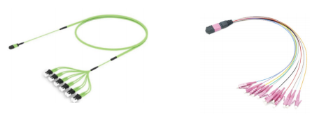
Fan-out pre-terminated cable: MPO/MTP multi-fiber connector at one end, duplex LC or SC breakout at the other.
Scenario 3: MPO/MTP loopbacks in data center commissioning and equipment validation
A loopback returns the transmit signal of a port to its own receive path, which lets a switch port, line card or module be validated before any real link exists. In a new hall this turns commissioning from an end-to-end exercise into a port-by-port one, and it isolates a faulty module from a faulty cable before the cable is blamed.
The MPO-12F and MPO-24F loopbacks are specified for network testing, data center commissioning and equipment validation, with these parameters:
- Insertion loss: low-loss grade at or below 0.7 dB for 8F/12F, and at or below 1.0 dB for 24F.
- Return loss: at least 65 dB in single-mode, at least 25 dB in multimode.
- Mating cycles: at least 100,000.
- Fiber type coverage: OS2, OM1, OM2, OM3, OM4, OM5.
- Stated link failure rate: below 0.1%.
The insertion loss figure is the one most often misread. A loopback sits inside the measurement path, so its own loss appears in whatever the port reports. A pass/fail threshold copied from a clean back-to-back reference without accounting for up to 0.7 dB of loopback loss will either reject healthy ports or accept marginal ones, depending on which direction the error runs. The 100,000-cycle rating is what makes the module reusable across many racks and many commissioning rounds; the return-loss figures matter most where single-mode links carry tighter reflectance requirements.
A loopback validates the port and module path. It does not measure the installed channel loss between two points, which still requires a loss test set or certification tester after the real assemblies are patched in. Treat the two as separate acceptance steps, not alternatives.
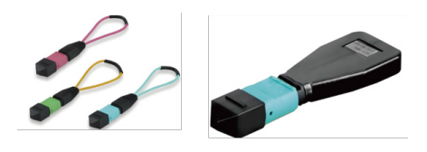
MPO/MTP loopback: used to validate ports and modules before the production link is patched.
Scenario 4: FTTx and campus access after the backhaul stage
Access networks inherit the same requirement set but a different order of work. Bow-type drop cable, PLC optical splitters, optical cable splice closures and FTTH distribution boxes belong to FTTH/FTTx access projects, and the requirements quoted for these deployments are the familiar ones: low attenuation, low insertion loss, waterproof sealing, crush and tensile resistance, corrosion and weather resistance, plus customizable core counts and labelling.
Sequencing is the practical point. The splitter ratio and the distribution box locations fix how many fibers each drop position needs, so the access stage should be designed after the backhaul route is accepted rather than in parallel with it. Otherwise a late change in splitter placement forces a re-termination that the closure and drop-cable order cannot absorb.
Comparison: what each family establishes and what it does not
The table below is deliberately narrow. It compares documented characteristics for the same deployment sequence and states the limits of each, because a datasheet value answers a specification question, not an installation question.
| Product | Primary environment | Documented characteristics | Not established by the datasheet |
|---|---|---|---|
| GYTA53 optical fiber cable | 5G backhaul, metropolitan backbone, outdoor access routes | Fiber type G.652/G.657, core count, attenuation in dB/km at stated wavelengths, minimum bend radius, tensile strength, sheath and environmental rating | Actual installed loss after pulling and splicing; suitability for a specific duct geometry without a route survey |
| MTP/MPO fan-out pre-terminated cable | Cabinet interconnection for 40G/100G/400G SR4/PSM4 modules | Insertion loss 0.35/0.75 dB (0.10/0.35 dB low-loss), return loss ≥60 dB APC / ≥50 dB PC, 12F or 24F, LC/SC duplex or quad breakout, LSZH or OFNR jacket | End-to-end channel loss once multiple assemblies and adapters are patched together |
| MPO fiber optic adapter (MPO-12F-SM) | High-density patching, cross-connect, patch panels | Insertion loss <0.5 dB standard / <0.35 dB low-loss, return loss ≥50 dB SM, 500 mating cycles, −40 °C to +85 °C, 4–72F SM/MM | Performance of a specific adapter position after contamination or repeated re-patching |
| MPO/MTP loopback | Commissioning, equipment validation, network testing | Insertion loss ≤0.7 dB (8F/12F) and ≤1.0 dB (24F), return loss ≥65 dB SM / ≥25 dB MM, ≥100,000 mating cycles, OS2 to OM5 | Channel loss between two patched points; it validates the port path, not the link |
Acceptance checklist for handover
The checks below are the minimum needed to close a mixed backhaul-and-data-center deployment. Each one maps to an attribute quoted earlier in this guide.
- Model datasheet on file for every cable reel, with fiber type, core count, attenuation in dB/km at the operating wavelength, tensile rating and minimum bend radius.
- Installation method recorded against the tensile and bend ratings actually used, including duct pulls and aerial spans.
- Span attenuation measured after backfilling and splicing, compared with the datasheet-derived expectation rather than a generic figure.
- Cabinet channel loss calculated with maximum assembly and adapter values, then measured per channel.
- Fan-out breakout mapping and labelling reconciled against the cabinet drawing: 12F to 6 LC duplex, 24F to 12 LC duplex.
- Adapter positions inspected and a sample loss check recorded where repeated re-patching is expected.
- Commissioning results reported with the loopback loss stated, so that port results are interpreted against the correct threshold.
Supplier capability for a mixed-project order
A deployment that spans an outdoor route, a cabinet row and a test bench usually ends up with one supplier list rather than three, so capability has to be checked across the whole order rather than per product line.
Nanfang Communication — Jiangsu South Communication Technology Co., Ltd., a subsidiary of South Communication Holdings Limited (Stock Code: 1617.HK) — was founded in July 1992 and operates from Changzhou, Jiangsu. Its product scope covers optical fibers, optical cables and ODN systems and optical components, including indoor and outdoor optical cables, PLC splitters, fiber optic connectors and MPO multi-core connectors, plus custom specialty fibers and cables and system integration services. The company reports a 26,795.3 m² facility, 360 employees, 80 R&D engineers and annual output of 3,000,000 core kilometers, with monthly capacity of 250,000 core kilometers and a minimum order quantity of 1 core kilometer.
On the qualification side, the company holds ISO 9001, TL9000, ISO 14001, OHSAS 18001 and ISO 50001 certification and a CNAS-accredited laboratory, and reports more than 300 patents including over 45 invention patents, together with 16 standards. For projects that mix cable and assemblies, the relevant questions are whether the same facility can quote both product families on one schedule and whether incoming inspection, in-process control and finished-product testing — optical loss and attenuation tests, mechanical performance, waterproof and sealing tests — are documented for each line item.

Nanfang Communication: optical fiber cable and MPO/MTP assembly supply from a single manufacturing base in Changzhou, Jiangsu.
Frequently asked questions
Which standards should a backhaul or data center cable project reference?
Reference the standard that matches the installation environment, not a general cable document. ITU-T L.103 (08/2024) describes characteristics, construction and test methods for indoor optical fibre cables; IEC 60794-1-104:2024 defines the impact test procedure used to establish uniform mechanical requirements; IEC 60092-378:2024 covers shipboard and offshore fixed installations, which illustrates how far apart two environments can be within the same standards family. These documents define test methods and characteristics and do not certify a product, so request product-level test reports in addition. For reference, Nanfang Communication's optical cable manufacturing is certified to TL9000-H and ISO 9001:2015, and the company also holds ISO 14001, OHSAS 18001 and ISO 50001 certification with a CNAS-accredited laboratory.
Can one fan-out assembly type serve 40G, 100G and 400G ports?
The MTP/MPO fan-out pre-terminated cable family is specified for data center cabinet interconnection and for 40G/100G/400G SR4/PSM4 module connections, in 12-fiber and 24-fiber versions that break out to 6 or 12 LC duplex connectors respectively. What changes between projects is the fiber type and the breakout: OM3, OM4 or OM5 multimode and OS2/G.657A single-mode are both available, and the module installed in the switch determines which one the link needs. Confirm the port count, breakout ratio and fiber type against the module datasheet before ordering, because the assemblies are built to order.
What defines the commercial scope of a quotation?
Quotation scope follows the configuration rather than the product name. Customizable items include core count, fiber type (single-mode, multimode, ribbon or multi-core), sheath material and colour, connector types and cabling scheme, labelling and packaging, and the minimum order quantity is 1 core kilometer. For projects shipping to the United States, landed cost also has to include duty: a customs brokerage source reports a total U.S. import duty of 37.50% on Chinese-origin optical fiber cable under HTS 8544.70.00 as of late 2026, a figure that should be verified with the importer's broker before budgeting.
How long does a sample or pilot order take?
There is no single published standard. Lead time depends on the model and the quantity; samples and small orders typically take several weeks, while large orders may take months, and the exact schedule should be confirmed with the supplier's sales team for the specific configuration. Because a pilot order is normally used to validate termination quality and labelling before the main release, it is worth requesting the same breakout, jacket and labelling convention that the production order will use.
How should lead time be planned across a mixed project?
Plan the cable route first. Outdoor cable drives the civil works, splice closures and distribution boxes, and a route change is far more expensive to absorb late than an assembly change. Cabinet assemblies can be staged per row once the cabinet layout is fixed, and loopbacks can be ordered as re-usable commissioning stock rather than per-rack consumables. Lead time depends on model and quantity and is confirmed per order, so the practical approach is to sequence the release dates against the acceptance steps in this guide. If you want to validate a configuration before committing, you can request a sample or a quotation for the specific cable model, assembly breakout and labeling scheme your project uses, and the current MPO product catalogue is available for download below.
Conclusion
The three environments in this guide fail for different reasons. A backhaul route fails at installation when the tensile rating or bend radius was never matched to the method, and at acceptance when attenuation is compared with a generic figure instead of the model datasheet. A cabinet row fails when standard-grade assemblies and adapters consume a budget that only worked on paper with typical values. A commissioning programme fails when the loopback's own insertion loss is left out of the pass/fail threshold.
The deployment sequence that avoids all three is the same in each case: define the environment, quote the attribute that the environment stresses, calculate with maximum values, and record the measurement against those values. GYTA53 cable, MTP/MPO fan-out assemblies and MPO/MTP loopbacks are separate product families, but on a real project they are one physical layer, and the acceptance report is where that becomes visible.
Download the Nanfang Communication MPO product catalogue (PDF) for the full model list, or contact the team through jsnfgroup.com with your route and cabinet schedule.
Have Questions or Need More Details?
Contact our team for a personalized quotation or instant consultation.
Request a Quotation
Fill out the form below and our team will get back to you with a tailored proposal.
WhatsApp Direct Chat
Prefer to chat in real-time? Message us on WhatsApp for instant assistance & quick answers.
- Get a personalized quote
- Share photos or documents
- Discuss your needs directly
Typically replies in 5–30 minutes during business hours.