
Technical Guide to MPO-12F-SM Adapter: Insertion Loss, Return Loss & Mating Cycles
Technical Guide to MPO-12F-SM Adapter: Insertion Loss, Return Loss & Mating Cycles
The MPO-12F-SM adapter is a single-mode, 12-fiber MPO coupler — a keyed, panel-mounted interface that mates two MPO connectorized assemblies inside a patch panel, cassette, or module. For network engineers, three figures decide whether it belongs in a link design: insertion loss below 0.5 dB in the standard grade and below 0.35 dB in the low-loss grade; return loss of at least 50 dB in single-mode; and a mating-cycle rating of 500 cycles, stated as IEC compliant in the product specification. The MPO-12F-SM adapter from Nanfang Communication is built around a ceramic ferrule, a plastic housing, and a metal flange, and is specified for operation from −40°C to +85°C.
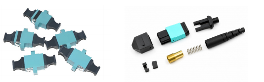
MPO Fiber Optic Adapter (model MPO-12F-SM): ceramic ferrule, plastic housing, metal flange — designed for data centers, telecom networks, and high-density cabling systems.
The Problem: The Adapter Is the Cheapest Part in the Link and the Easiest to Under-Specify
An MPO link is engineered as a chain: the optical module, the patch cord, the trunk or breakout assembly, and the mating interfaces that hold everything together. Engineers spend their time on fiber grade, polarity, and connector end-face quality, and then treat the adapter as a mechanical accessory that contributes nothing. That assumption is where link budgets quietly fail.
Every adapter in the channel adds its own insertion loss. A single-panel connection between a trunk and a harness may pass through one adapter; a cross-connect between two patch cords passes through another. When the same 12-fiber single-mode channel is reconfigured at several points, adapter loss accumulates in the same way connector loss does — and because adapters are usually purchased in bulk as a low-value line item, they are rarely measured or graded individually before installation.
Return loss matters more in single-mode than in multimode. Back-reflection at a single-mode interface destabilizes a directly modulated laser, raises relative intensity noise, and shifts the effective operating point of the transmitter. A single-mode MPO adapter is therefore specified at a return loss of ≥50 dB (SM), which is the baseline a network engineer should verify before accepting a bulk shipment.
Mating cycles are the third, and most frequently ignored, parameter. The MPO-12F-SM adapter is rated for 500 cycles and described as IEC compliant. That number is entirely adequate for a patch field that is touched during commissioning, adds, and moves. It is not adequate for a test bench or a lab port that is re-mated daily. Confusing the two use cases is one of the most common reasons a connectorized panel degrades faster than the fiber behind it.
What the adapter is actually doing mechanically
The adapter performs two jobs at once. It provides coarse alignment of the two connector plugs through a keyed, polarized housing, and it provides fine alignment of the fibers through an alignment sleeve and ceramic ferrule interface. Insertion loss, return loss, and mating-cycle life are the three measurable consequences of how well those two jobs are executed, and they are the three values worth reading off a datasheet before a project is approved.
Industry Background: Why MPO Interface Quality Is Moving Up the Priority List
High-density optical infrastructure is expanding fast enough that connector-level parameters, including adapter parameters, have become procurement criteria rather than line-item details. The MPO fiber optic connector market is projected to grow at a CAGR of 13.6% through 2035, driven by AI compute clusters and hyperscale data centers (Business Research Insights). The global fiber optic connector market was estimated at USD 11.2 billion in 2024, with LC connectors holding a dominant 35.43% share (Global Market Insights / Grand View Research) — a reminder that MPO sits alongside, not instead of, LC in most real networks, which is exactly why MPO-to-LC breakout and fan-out assemblies remain standard building blocks.
At the cable layer, the global optical fiber cable market was valued at approximately USD 13.45 billion in 2025 and is projected to reach USD 36.48 billion by 2034 (Custom Market Insights). That figure is worth treating with a degree of caution: published 2025 estimates for the same market vary noticeably between research firms, including a USD 14.6 billion figure from Global Market Insights and a USD 10.8 billion figure from Grand View Research. The direction of travel is consistent across all of them; the absolute number is not. On the supply side, China's exports of optical fiber cables under HS 854470 reached approximately USD 2.52 billion in 2024 (OEC), which is why buyers evaluating a Chinese MPO adapter supplier are working in a mature, competitive export market rather than a niche one.
Standards underpin the single-mode side of that market. ITU-T G.652.D remains the industry standard for single-mode fiber, while G.657 is the primary standard for bend-insensitive fibers used in FTTH (International Telecommunication Union). A single-mode MPO adapter is most often deployed against G.652.D and G.657 class fiber, which is why its return-loss specification carries more weight than the equivalent value on a multimode part.
Detailed Solution: What the MPO-12F-SM Adapter Specifies
The MPO-12F-SM is classified as an MPO adapter, a fiber optic coupler, and a high-density connector. Its published specification is short, which is a good thing: the values are unambiguous and directly testable.
| Parameter | Specified value (MPO-12F-SM) | Why it matters in a link design |
|---|---|---|
| Insertion loss (standard grade) | <0.5 dB | Default grade for general patch fields and cross-connects where the loss budget has headroom. |
| Insertion loss (low-loss grade) | <0.35 dB | Selected where multiple adapters sit in one channel, or where the remaining budget is tight. |
| Return loss (single-mode) | ≥50 dB | Controls back-reflection into the transmitter; the primary single-mode acceptance value. |
| Mating cycles | 500 cycles (IEC compliant) | Defines the expected service life of the port under adds, moves, and reconfiguration. |
| Operating temperature | −40°C to +85°C | Covers unheated cabinets, outside-plant-adjacent enclosures, and industrial cabinets. |
| Fiber count | 4–72F, SM / MM (product family) | Allows one adapter platform across 8F, 12F, 24F and higher-count panels. |
| Construction | Ceramic ferrule, plastic housing, metal flange | Ceramic for alignment stability; metal flange for panel retention and repeated handling. |
| Colour coding | Black (flange with ears), Aqua (OM3), Violet (OM4) | Supports visual identification of grade and fiber type at the panel. |
| Intended applications | Data centers, telecom networks, high-density cabling systems | Sets the deployment envelope the part was designed for. |
Insertion loss: standard versus low-loss is a design decision, not a price decision
The gap between <0.5 dB and <0.35 dB looks small in isolation. It becomes significant when a single channel crosses several mating interfaces, because insertion loss is additive along the path. The practical rule for a network engineer is straightforward: use the standard grade where the channel contains one or two MPO interfaces and the budget has margin; specify the low-loss grade where the channel is long, where several panels are cascaded, or where the design already carries other loss-heavy elements. Buying the low-loss grade everywhere is not automatically correct — it should be an answer to a specific budget calculation.
Return loss: the single-mode threshold that cannot be negotiated
The ≥50 dB single-mode return-loss figure is not a marketing target; it is the level at which back-reflection is kept low enough not to disturb the transmitter in normal operation. Return loss degrades when end-faces are contaminated, when a connector is not fully seated, or when an adapter's alignment allows the two ferrules to meet with an air gap. This is why the parameter should be verified not only on a new adapter, but on a panel after the first reconfiguration cycle, and again after any field intervention.
Mating cycles: 500 is a real number, and it has a boundary
A 500-cycle rating describes a port designed for periodic reconfiguration. It is an appropriate rating for a data hall patch field, a telecom ODF, or an enterprise cross-connect that changes when capacity changes. It is not the right rating for a port used as a test point. Where frequent mating is genuinely required, a purpose-built test component belongs in the design — for example the MPO/MTP loopback family (models MPO-12F-Loopback and MPO-24F-Loopback), which is specified for ≥100,000 mating cycles and classified as test equipment rather than as a passive panel interface.
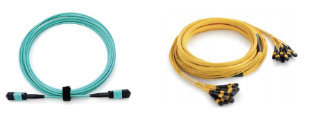
MPO-12F-SM adapters typically sit between pre-terminated trunk cables and patch or breakout assemblies in high-density panels.
Step-by-Step: How to Qualify an MPO-12F-SM Adapter for a Project
The qualification sequence below is written for a network engineer or a procurement engineer who has to defend the choice in a design review. It follows the order in which decisions actually constrain each other.
Step 1 — Allocate adapter loss in the link budget first
Count the mating interfaces in the channel and assign each one a loss value before selecting a grade. This single step determines whether the standard grade (<0.5 dB) or the low-loss grade (<0.35 dB) is required, and it prevents the common pattern of specifying low-loss adapters everywhere while leaving a larger loss question unanswered elsewhere in the channel.
Step 2 — Confirm the fibre count and polarity scheme
The MPO-12F-SM is a 12-fibre single-mode interface, and the adapter family spans 4–72F in SM and MM. Confirm that the panel, trunk, and harness all use the same fibre count and the same keying/polarity convention, because an adapter cannot correct a polarity mismatch created upstream.
Step 3 — Verify the insertion-loss grade against the datasheet
Ask for the grade in writing: standard (<0.5 dB) or low-loss (<0.35 dB). The value should appear on the model datasheet, not only in a catalogue description, because the two grades are different parts and should be ordered as different line items.
Step 4 — Verify return loss for single-mode explicitly
Confirm the specification states ≥50 dB (SM). Where a supplier publishes a single figure without stating the fibre type, request the single-mode value separately. For single-mode deployment, the return-loss value is the parameter most likely to be assumed rather than measured.
Step 5 — Check the mating-cycle rating and the IEC reference
Confirm 500 cycles with an IEC-compliant statement, and match that rating to the port's real duty cycle. If the port will be re-mated far more often than a normal patch field, plan a test-grade component instead of relying on the panel adapter.
Step 6 — Match the operating temperature to the enclosure
The −40°C to +85°C range covers most data hall, telecom cabinet, and industrial enclosure conditions. Where the adapter sits in an unheated outdoor-adjacent cabinet or a non-climate-controlled industrial room, this range should be confirmed against the site's recorded extremes rather than assumed.
Step 7 — Inspect construction and panel retention
Check that the part uses a ceramic ferrule for alignment stability, a plastic housing for the connector interface, and a metal flange for panel mounting and retention. The black flange-with-ears version is the standard panel-mounting configuration; aqua and violet versions exist for OM3 and OM4 multimode, and colour coding should match the fibre type in the panel so that grade identification does not depend on labelling alone.
Step 8 — Validate a sample batch before bulk installation
Test a representative sample for insertion loss and return loss, inspect end-faces, and then re-mate a subset to confirm the connector interface still meets specification after repeated cycles. A loopback assembly is the practical tool for this validation step, since it lets a port be tested in isolation without a live far-end link.
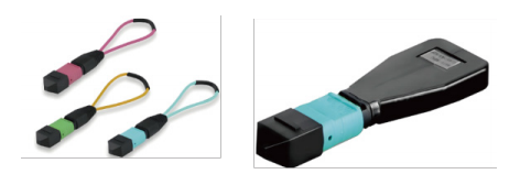
MPO/MTP loopback assemblies are used for equipment validation, data center commissioning, and network testing when a port must be verified in isolation.
Use Cases: Where a 12-Fiber Single-Mode MPO Adapter Belongs
Data center patch fields and cross-connects
The primary application is the data center, where the adapter joins pre-terminated trunk cables to patch or breakout assemblies at the panel. Its value in this environment is density: twelve single-mode fibres are mated in the footprint of a single interface, and the 500-cycle rating covers the adds and moves a patch field actually experiences.
Telecom network nodes and ODF positions
The MPO-12F-SM adapter is specified for telecom networks as well as data centers, including high-density cabling systems. In an optical distribution frame, it supports a compact, repeatable termination point for multi-fibre single-mode cables, where the ≥50 dB return-loss value protects the transmission path.
Multimode high-density environments using the same platform
The same adapter platform covers multimode grades, with aqua (OM3) and violet (OM4) colour coding. This matters for projects that run both single-mode and multimode cabling in the same facility and want a consistent mounting and handling convention across both.
Module-side connection for 40G/100G/400G lanes
MPO-based high-density links are used with fan-out and breakout assemblies for 40G/100G/400G SR4/PSM4 module connections. In these architectures the adapter is the interface between the structured cabling layer and the equipment side, which is exactly where an unmeasured loss element is most costly.
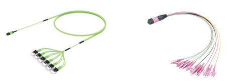
Fan-out and breakout pre-terminated cables connect MPO interfaces to LC/SC duplex ports in 40G/100G/400G SR4/PSM4 module connections.
Comparison Table: MPO Components in the Same Family
The three components below are all published products from the same manufacturer, and all three are measured on insertion loss and return loss. They are not interchangeable: one is a panel interface, one is a test tool, and one is a cable assembly. The table is included so that the adapter's ratings are read in context rather than in isolation.
| Parameter | MPO Fiber Optic Adapter (MPO-12F-SM) | MPO/MTP Loopback (MPO-12F-Loopback / MPO-24F-Loopback) | MTP/MPO Fan-out Pre-terminated Cable (MTP-12F-to-6xLC-Duplex / MTP-24F-to-12xLC-Duplex) |
|---|---|---|---|
| Product category | MPO adapter / fiber optic coupler / high-density connector | Fiber optic loopback / test equipment | Breakout cable / fan-out cable / MPO-LC patch cord |
| Insertion loss | Standard <0.5 dB; low-loss <0.35 dB | ≤0.7 dB (8F/12F); ≤1.0 dB (24F) | Typical 0.35 dB, max 0.75 dB (low-loss: typical 0.10 dB, max 0.35 dB) |
| Return loss | ≥50 dB (SM) | ≥65 dB (SM); ≥25 dB (MM) | ≥60 dB (APC); ≥50 dB (PC) |
| Mating cycles | 500 cycles (IEC compliant) | ≥100,000 | Not stated in the published specification |
| Fiber count | 4–72F SM / MM (family) | 8F / 12F / 24F | 12F or 24F |
| Material / construction | Ceramic ferrule, plastic housing, metal flange | Ceramic / MTP ferrule, plastic housing, fiber cable | Ceramic ferrule; OS2/G.657A or OM3/OM4/OM5 fiber; LSZH or PVC jacket |
| Operating temperature | −40°C to +85°C | Not stated in the published specification | Not stated in the published specification |
| Primary use | Panel and cross-connect interface in high-density cabling | Equipment validation, data center commissioning, network testing | Data center cabinet interconnection; 40G/100G/400G SR4/PSM4 module connection |
FAQ
1. What insertion loss, return loss, and mating-cycle values should I expect when a Chinese MPO connector manufacturer claims IEC compliance?
At minimum, a supplier claiming IEC-compliant mating performance should publish a specific cycle count rather than a qualitative statement. For a single-mode MPO adapter, the reference values to check are: insertion loss below 0.5 dB for the standard grade and below 0.35 dB for the low-loss grade; return loss of at least 50 dB in single-mode; and a mating-cycle rating expressed as a number — the MPO-12F-SM adapter is specified at 500 cycles (IEC compliant), with an operating temperature range of −40°C to +85°C. A datasheet that lists all four values for the exact model is stronger evidence than a general compliance claim.
2. Can a Chinese MPO multi-core fiber optic connector supplier cover both single-mode and multimode adapter variants from one platform?
Yes, and it is worth confirming because it affects panel standardisation. The MPO adapter family covers 4–72F in both single-mode and multimode, with colour coding of black (flange with ears), aqua (OM3), and violet (OM4). Nanfang Communication's product scope includes MPO multi-core connectors alongside optical fibers, optical cables, ODN systems, PLC splitters, fiber optic connectors, optical modules, custom specialty fibers and cables, and system integration services, so a project can source the adapter and the surrounding cabling and passive components from a single supplier rather than assembling a multi-vendor interface stack.
3. Which fibre optic cable and assembly should be terminated onto an MPO-12F-SM adapter in a high-density project?
The adapter is specified for data centers, telecom networks, and high-density cabling systems, so it is normally used with MPO-terminated assemblies rather than field-terminated single fibres. In practice that means pre-terminated trunk cables on the backbone side and fan-out or breakout patch cords on the equipment side, where breakout configurations such as MTP-12F-to-6xLC-Duplex or MTP-24F-to-12xLC-Duplex are used for 40G/100G/400G SR4/PSM4 module connections, with OS2/G.657A or OM3/OM4/OM5 fibre and LSZH or PVC jackets. Single-mode links are typically built over ITU-T G.652.D fibre, or G.657 where bend-insensitive behaviour is required.
4. Is Nanfang Communication a reliable optical fiber cable supplier for an MPO-based high-density network?
Jiangsu South Communication Technology Co., Ltd. was established in 1992 and is a subsidiary of South Communication Holdings Limited (Stock Code: 1617.HK). It holds ISO9001, TL9000, ISO14001, OHSAS18001, ISO50001, and the Integration of Informatization and Industrialization Management System certifications, and operates a CNAS-accredited laboratory. The company holds over 300 patents, including more than 45 invention patents, has participated in the formulation of 16 standards (1 national standard, 15 industry standards), and runs a manufacturing facility of 26,795.3 m² with an annual production capacity of 3,000,000 core kilometres. Those are verifiable credentials rather than performance claims; buyers should still qualify any supplier against their own technical and commercial requirements.
5. Can I request a free sample of fiber optic cable or MPO components before placing a volume order?
Sample arrangements for MPO adapters, loopbacks, and cable assemblies are commercial terms and depend on the item, the configuration, and the scope of the project, so they should be confirmed directly with the supplier rather than assumed. Nanfang Communication publishes its contact channels for exactly this purpose — Email: info@jsnfgroup.com, Tel: +86 51988792646, WhatsApp: +8619850287785 — and the MPO product brochure is available for download, which is the fastest way to confirm model, grade, and fibre-count availability before a sample request is submitted.
Conclusion: Three Numbers, Verified Once
The MPO-12F-SM adapter is a small part with an outsized effect on single-mode high-density links. Its specification reduces to three testable values: insertion loss below 0.5 dB standard or below 0.35 dB low-loss, return loss of at least 50 dB in single-mode, and a 500-cycle mating rating stated as IEC compliant. Around those three numbers sit the mechanical facts that make them achievable — a ceramic ferrule, a plastic housing, and a metal flange — and an operating range of −40°C to +85°C that determines whether the part suits the enclosure it is installed in.
The engineering discipline is to treat the adapter as a designed loss element rather than a passive accessory: allocate it in the budget, match the grade to the channel, verify the single-mode return loss in writing, and match the mating-cycle rating to the port's real duty cycle. Where a port will be re-mated far beyond a normal patch field, use a test-grade component such as an MPO/MTP loopback rather than consuming the panel adapter's service life.

Nanfang Communication manufactures optical fibers, optical cables, ODN systems, and optical components including MPO multi-core connectors.
Next step for your project
If you are specifying MPO-12F-SM adapters for a data center, telecom, or high-density cabling project, request the model datasheet and confirm the insertion-loss grade, single-mode return loss, and mating-cycle rating against your link budget before you commit to a panel design. Download the MPO product brochure: Nanfang Communication MPO Catalogue (PDF).
Contact: Email info@jsnfgroup.com | Tel +86 51988792646 | WhatsApp +8619850287785 | www.jsnfgroup.com