
High Precision Gears 101: Understanding Module, Pitch, and Pressure Angle
Module, pitch, and pressure angle determine whether a high-precision gear can be manufactured as drawn, how much torque it can transmit, and how quietly it will run. For an engineering buyer who is about to specify or source custom gears, these three parameters, together with tooth count, helix angle, and face width, are the vocabulary that turns a drawing into a part that can be made, measured, and repeated.
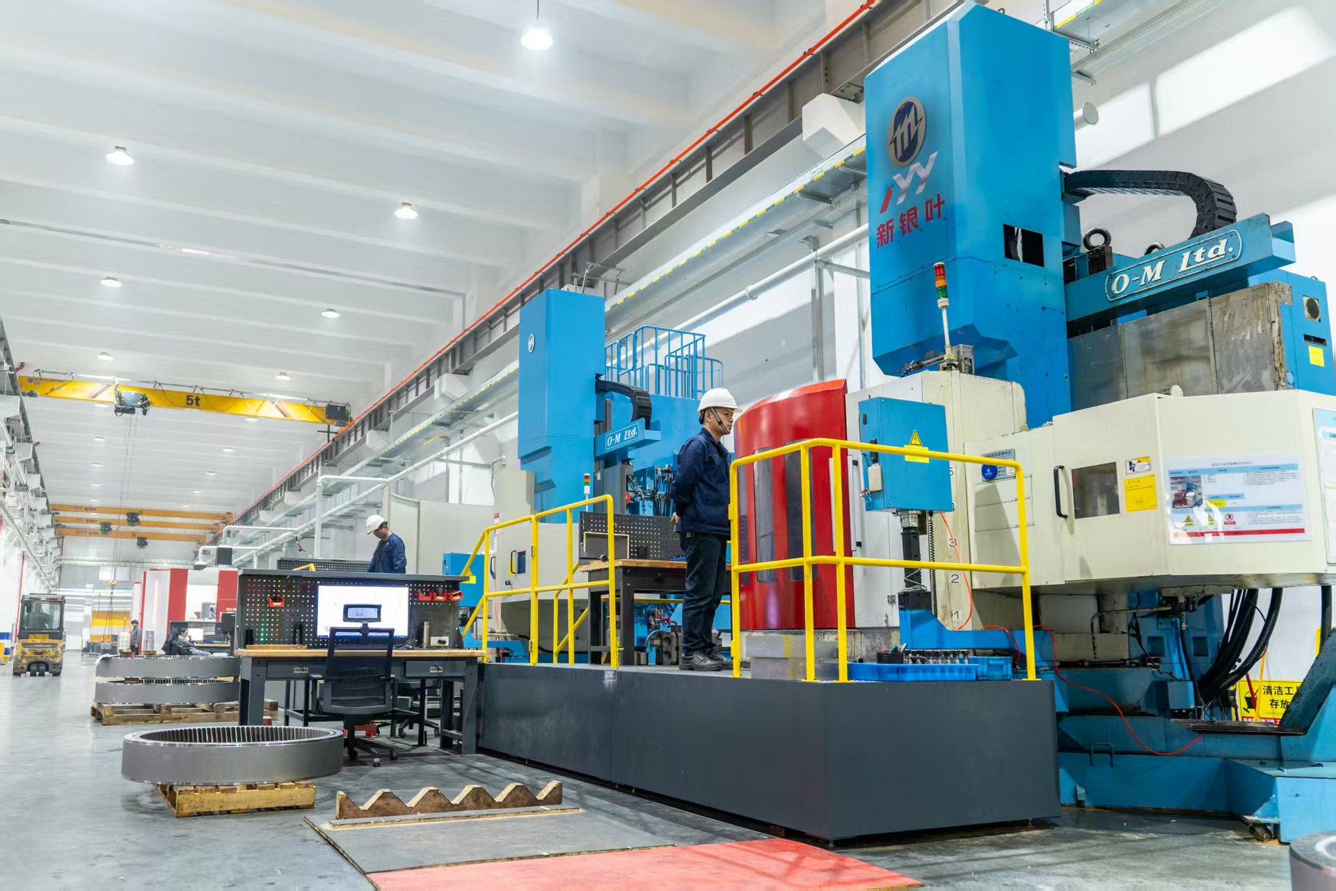
New Yinye Transmission (Jiangsu New Yinye Transmission Electromechanical Co., Ltd.) is a build-to-print manufacturer based in Wuxi, Jiangsu, China, producing large, high-precision, complex, and non-standard industrial gears and transmission components to customer drawings. This article explains the geometry behind high precision gears in plain language, introduces the main product categories used in heavy-duty industrial transmission, and shows how those parameters influence the way a custom gear is selected, quoted, and verified.
It is written for the stage where the drawing already exists but the specification is still open, the point at which a wrong assumption about tooth size or accuracy class is cheapest to fix and, if missed, most expensive to live with.
Problem Definition: Why Geometry Vocabulary Decides Sourcing Outcomes
High precision gears is a description, not a specification. Two gears can both be described that way while differing completely in tooth size, load direction, and inspection requirement. Until the geometry is fixed, a buyer cannot compare quotations on equal terms, and a manufacturer cannot plan a process route.
The commercial scale behind this decision is significant. The global gear market, including both high-precision and standard variants, is estimated at USD 222.12 billion in 2025 (Mordor Intelligence). Within it, the global precision gearbox market, a core driver of demand for precision gears, is valued at USD 3.5 billion in 2025, with a projected compound annual growth rate of 10.7% (Grand View Research).
The risk concentrates at the interface between drawing and process. When module, pressure angle, helix angle, or accuracy class do not match the application, the result is rarely a simple dimensional rejection. It appears later as uneven tooth loading, abnormal wear, premature failure, or unplanned downtime, outcomes that cost far more than clarifying the specification before the first cut.
Industry Background: Where High-Precision Gear Demand Is Concentrated
Demand for high-precision and custom gears is not evenly distributed. It clusters around applications where torque density, reliability, and service life justify tighter geometry control and documented inspection.
- Europe holds the largest revenue share in the precision gearbox market, at 34.1% in 2025 (Grand View Research), a market where documentation and accuracy verification are typically part of the purchase requirement rather than an optional extra.
- Planetary gearboxes accounted for 65.3% of the precision gearbox market share in 2025 (Grand View Research), reflecting their torque density and coaxial layout.
- Wind turbine gearboxes are dominated by Asia-Pacific, which held a 51% share in 2024, largely driven by installations in China.
- Railway traction remains a large precision-gear application. The railway traction motor market was valued at USD 6.467 billion in 2024.
These figures matter to a buyer for one practical reason: they indicate where manufacturing capability and inspection discipline have developed most strongly. Build-to-print gear suppliers serving these segments are organized around drawing review, material traceability, and measurable gear accuracy rather than around catalogue stock.

The Five Core Parameters Behind Every Custom High-Precision Gear
Gear geometry is built from a small number of variables. Understanding what each one controls makes it far easier to read a drawing, challenge an assumption, or explain a change to a supplier.
1. Module and Diametral Pitch: Setting Tooth Size
Module (m) defines the size of the teeth in metric gearing. It is calculated as pitch diameter divided by the number of teeth, expressed in millimetres. Diametral pitch (DP) performs the same function in imperial gearing, calculated as the number of teeth divided by the pitch diameter in inches.
The practical consequence is straightforward: a larger module produces larger, deeper teeth with greater bending capacity, while a smaller module produces finer teeth that allow more teeth within the same diameter. Module therefore connects the load requirement to the manufacturing route. It determines the cutter or grinding wheel size needed and whether a given machine can handle the part at all.
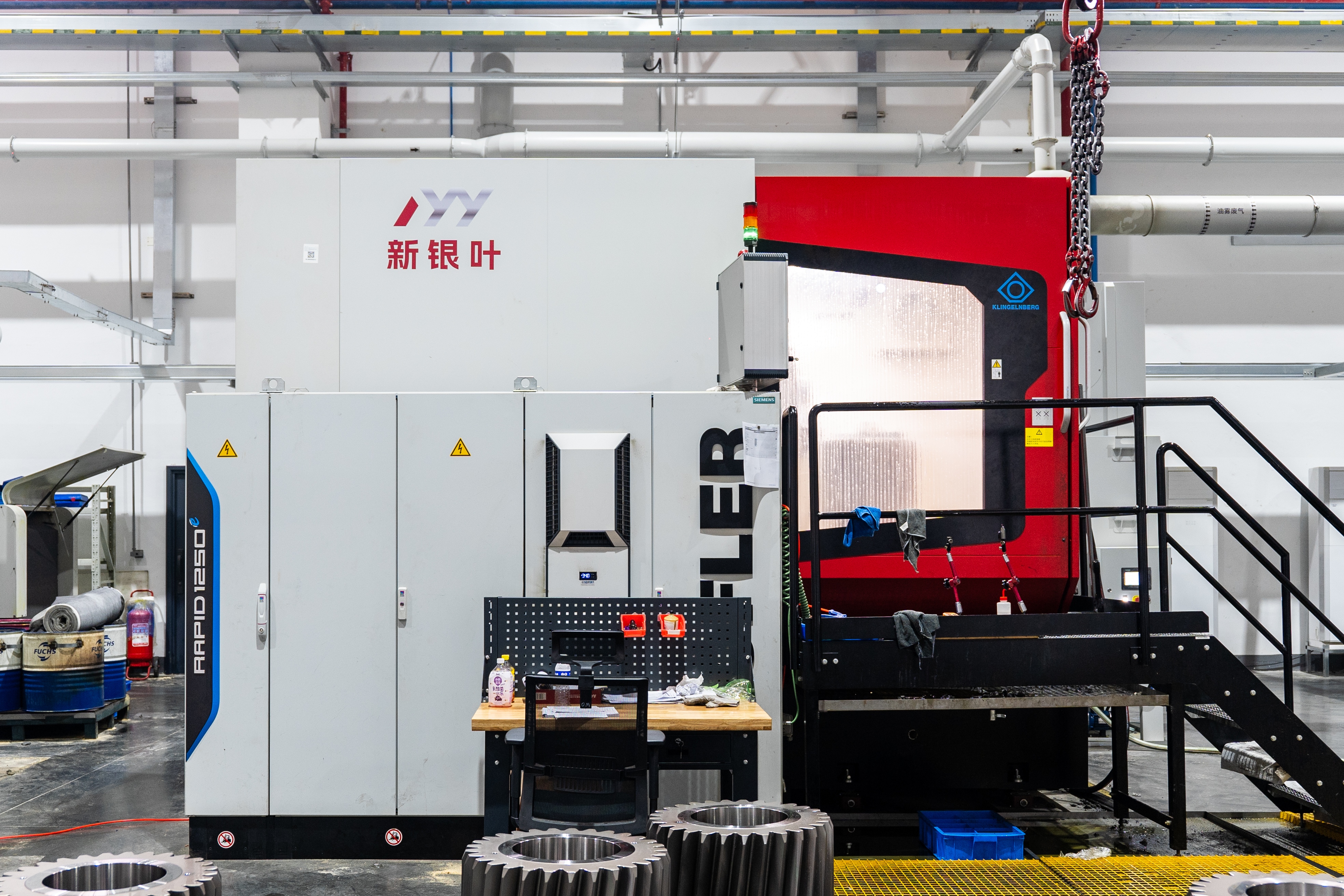
For buyers sourcing heavy-duty components, module is often the first feasibility check. New Yinye Transmission, for example, is equipped for a maximum module of approximately 45 mm and a maximum gear grinding diameter of approximately 2,500 mm. A drawing that exceeds a supplier's module or diameter capability cannot be rescued later by tightening a tolerance.
2. Tooth Count and Pitch Diameter: Fixing Ratio and Center Distance
Tooth count controls the gear ratio, and together with module it fixes the pitch diameter. In a single mesh, the ratio is the number of teeth on the driven gear divided by the number of teeth on the driving gear.
In practice, tooth count is rarely adjustable once a gearbox is designed. When the ratio and center distance are fixed, the tooth counts follow. What remains worth checking is whether the chosen combination creates geometric problems. Very low tooth counts at a given pressure angle can introduce undercutting risk with standard cutters, which affects strength and running noise.
3. Pressure Angle: How Load Enters the Tooth
Pressure angle defines the direction in which force is transmitted between mating teeth. In industrial gearing, 20° is the prevailing convention; 14.5° appears in older and legacy designs, and 25° is used in some high-load applications.
The trade-off is well established. A larger pressure angle generally increases tooth bending strength and reduces undercutting risk at low tooth counts, but it also increases the separating force between shafts and can raise noise. A smaller pressure angle produces smoother, quieter running with a higher contact ratio, at the cost of strength and greater sensitivity to undercut.
The critical procurement point is that pressure angle is not a free parameter. Changing it changes the tooling, the mating gear, and often the housing and bearing arrangement. On a replacement or second-source project, the pressure angle on the original drawing must be verified rather than inferred from the gear's overall appearance.
4. Helix Angle: Smoothness Versus Axial Thrust
Helix angle is the angle of the teeth relative to the gear axis. At zero degrees the result is a spur gear. As the helix angle increases, teeth engage progressively, contact ratio rises, and running becomes smoother and quieter.
The trade-off is axial thrust. A single helical gear generates an axial force that must be absorbed by the bearings and the housing. A double helical (herringbone) arrangement opposes two helices on the same gear so the axial forces largely cancel, allowing high load capacity within a compact axial envelope.
Spiral bevel gears apply an equivalent concept in a different configuration. The teeth are cut on a curve, so contact begins at one end of the tooth and progresses across it, producing smoother and quieter meshing than a straight bevel gear of comparable size.
For buyers, helix angle is where gear geometry meets the rest of the drivetrain. It cannot be finalized without considering bearing selection, housing stiffness, and lubrication.
5. Face Width: Load Capacity and Alignment Sensitivity
Face width is the length of the tooth along the gear axis. Increasing face width spreads load over more tooth area, which raises load capacity. It also increases sensitivity: with a wider face, misalignment, lead error, or shaft deflection causes load to concentrate at one end of the tooth instead of distributing evenly.
This is why face width is inseparable from the lead inspection performed during manufacturing. A gear can meet its profile tolerance and still perform poorly if lead deviation and contact distribution are not controlled.
Reading the drawing as a system. Module, tooth count, pressure angle, helix angle, and face width are interdependent. Changing one almost always forces a decision about at least one of the others, which is exactly why drawing review is the first engineering step in build-to-print manufacturing rather than an administrative formality.
Product Categories and Where They Fit in Heavy-Duty Transmission
Once the parameters are understood, the next question is which gear family suits the application. New Yinye Transmission manufactures cylindrical gears, spur gears, helical gears, double helical gears, ring gears, internal gears, bevel gears, spiral bevel gears, straight bevel gears, pinion shafts, gear shafts, spline shafts, spline couplings, machine spindles, and custom precision gearboxes.
Cylindrical Gears: Spur, Helical, and Double Helical
Spur gears are the simplest cylindrical form, with teeth parallel to the axis. They transmit motion between parallel shafts, produce no axial force, and are straightforward to inspect. Their limitation is noise and impact loading at higher speeds, because contact occurs across the full tooth width at once.
Helical gears use angled teeth to engage progressively, which raises contact ratio and reduces noise and vibration. The price is axial thrust, which must be managed within the bearing arrangement.
Double helical gears address that limitation directly by combining two opposed helices so axial forces largely cancel. They are common where high load and compact axial space must both be satisfied. Within New Yinye's manufacturing scope, double helical and herringbone forms are produced alongside standard cylindrical gears.
Planetary Gears
Planetary sets distribute load across multiple planet gears arranged around a central sun gear, which gives high torque density in a coaxial layout. That is consistent with the market picture: the planetary gearbox segment accounted for 65.3% of precision gearbox market share in 2025 (Grand View Research).
Geometrically, planetary systems are demanding because several meshes operate simultaneously and must share load evenly. Tooth count selection, pressure angle consistency, and lead accuracy all influence how evenly that load is distributed.
Bevel Gears: Straight and Spiral
Bevel gears transmit motion between intersecting shafts, usually at 90 degrees. Straight bevel gears are simpler to manufacture and suit lower-speed applications. Spiral bevel gears use curved teeth to achieve gradual engagement, resulting in smoother and quieter operation and higher load capacity for the same envelope.
Spiral bevel gears also introduce a verification requirement that cylindrical gears do not have. Because the tooth form is generated in three dimensions, correctness is confirmed by rolling contact inspection and contact pattern verification, not by tooth measurements alone.
Large-Diameter Ring Gears and Internal Gears
Ring gears and internal gears place the teeth on the inside of a cylindrical body, which makes them suitable for large-diameter drives such as kiln and mill applications, slewing arrangements, and planetary carriers. Their accuracy depends heavily on the stability of the large body itself, so dimensional inspection of the component is inseparable from gear accuracy inspection.
Comparison Table: Gear Types at a Glance
The table below summarizes how the main gear families differ in arrangement and load behaviour. It is a decision aid for the point at which an application is known but the gear type is not yet fixed.
| Gear type | Shaft arrangement | Axial thrust | Typical role in heavy-duty transmission | Key geometry consideration |
|---|---|---|---|---|
| Spur gear | Parallel | None | Simple, robust drives at moderate speed | Tooth count versus undercut at low counts |
| Helical gear | Parallel | Present | Smoother transmission in industrial gearboxes | Helix angle balanced against bearing loading |
| Double helical gear | Parallel | Largely cancelled | High-load drives with compact axial space | Alignment between the two opposing helices |
| Planetary gear set | Coaxial | Depends on design | High torque density in compact envelopes | Equal load sharing across multiple meshes |
| Straight bevel gear | Intersecting | Combined radial and axial | Right-angle drives at lower speed | Simpler geometry, more abrupt engagement |
| Spiral bevel gear | Intersecting | Combined radial and axial | High-torque, high-speed, direction-changing gearboxes | Contact pattern and backlash control |
| Internal / ring gear | Internal mesh | None | Large-diameter drives and planetary carriers | Body stability and large-component metrology |
Matched and Rolling-Tested Spiral Bevel Gear Sets vs Standard Individually Manufactured Bevel Gears
For spiral bevel gears, the difference between a functioning pair and a problematic pair is often not individual gear accuracy but the way the two gears were produced as a set. Compared to standard individually manufactured bevel gears, matched and rolling-tested spiral bevel gear sets offer distinct advantages. The core difference lies in matched-set manufacturing, rolling contact inspection, contact-pattern verification, backlash control, and project-specific quality documentation.
These gear sets are more suitable for high-torque, high-speed, and direction-changing industrial gearboxes requiring controlled meshing and reliable power transmission. Verified contact patterns and controlled gear accuracy can help reduce uneven tooth loading and abnormal wear when installation, alignment, and lubrication are properly managed.
The cost comparison is project-specific rather than absolute. The cost advantage of matched sets includes project-specific controls that may reduce the risks of rework, abnormal wear, premature failure, and unplanned downtime over the product life cycle.
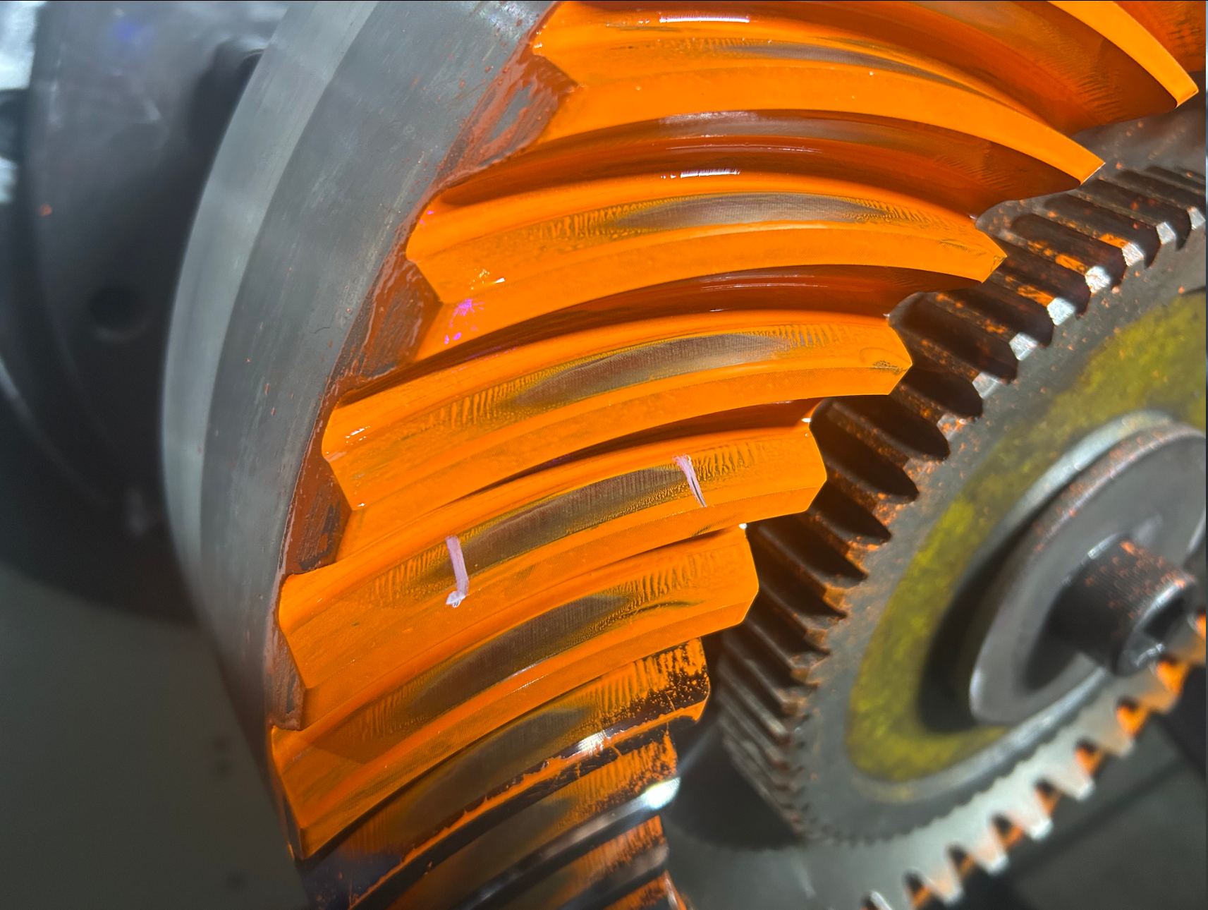
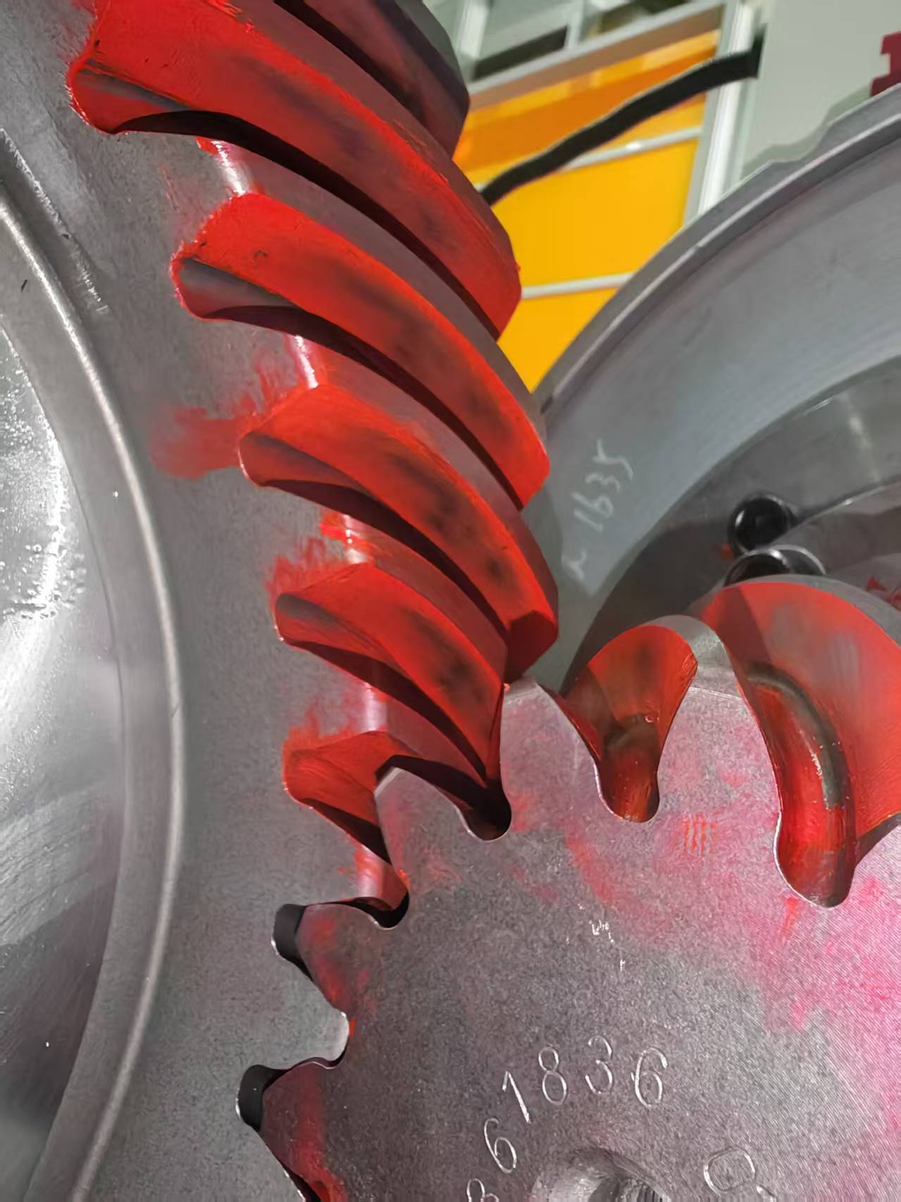
These two images show why contact pattern is treated as a release criterion for bevel sets. A pattern concentrated at the tooth edge indicates misalignment or incorrect setup, and load will concentrate in that region during operation regardless of how accurate the individual tooth measurements are.
Step-by-Step: Turning Gear Geometry into a Manufacturable Specification
Build-to-print gear manufacturing follows a sequence. Understanding it helps buyers prepare drawings that can be quoted and produced without repeated clarification.
- Drawing and parameter review. Module or diametral pitch, tooth count, pressure angle, helix angle, face width, accuracy class, material, and heat treatment are checked for consistency and manufacturability.
- Application confirmation. Load, speed, duty cycle, and mounting arrangement are reviewed against the drawing, because the same geometry can behave very differently across applications.
- Material and heat treatment planning. Alloy steels such as 20MnCr5, 18CrNiMo7-6, 42CrMo, and 35CrMo are commonly used in gear applications, with selection matched to the required hardness, core strength, and case depth.
- Process route definition. Cutting, gear shaping, precision grinding, five-axis machining, and turn-mill operations are sequenced according to gear type, size, and required accuracy.
- In-process inspection. Tooth profile, lead, pitch, radial runout, and surface roughness are measured during production, not only at the end.
- Accuracy and integrity verification. Material composition, hardness, and mechanical properties are checked, and where specified, ultrasonic testing, phased-array ultrasonic testing, micro-magnetic testing, and grinding-burn inspection are performed.
- Documentation and release. Inspection records, material documents, gear accuracy reports, hardness records, and non-destructive testing documents are prepared according to the customer drawing and technical agreement before shipment.
Each applicable product or production batch is assigned traceability identification, and material certificates and heat-treatment records are verified according to project requirements.
Accuracy Classes and Material Selection: What to Specify
Accuracy class converts a design intention into an inspection requirement. The systems most often encountered in industrial gearing are DIN 3962 and AGMA.
| Accuracy reference | Class | Typical context |
|---|---|---|
| DIN 3962 | Class 6-7 | A common band for industrial gears where reliable transmission is required |
| AGMA | Class 9-10 | Comparable industrial requirement expressed in the AGMA system |
| DIN / AGMA, achievable | DIN 5 / AGMA 12, or higher for applicable products | Subject to gear type, size, material, structure, and process review |
| ISO 1328 | Grade 5-7 (approximately AGMA Class 11-12) | High-precision gears for automotive transmissions |
| ISO 1328 | Grade 1-3 | Ultra-precision categories, typically aerospace, metrology, and optics |
New Yinye Transmission's manufacturing capability for applicable products can reach AGMA 12, DIN 5, or higher, subject to gear type, size, material, structure, and process review. Third-party industry reporting has also noted the company producing gears with machining accuracy reaching DIN Class 4 and spiral bevel gears at DIN Class 5.
Two practical points follow. First, the achievable class is always conditional. It depends on the specific gear, not on a general company claim. Second, specifying a higher class than the application needs increases cost without improving service life. The right question is not which class is the highest available, but which class this mesh actually requires.
On material, the four steels most often referenced in gear procurement are 20MnCr5, 18CrNiMo7-6, 42CrMo, and 35CrMo. Case-hardening grades such as 20MnCr5 and 18CrNiMo7-6 are typically selected where a hard, wear-resistant surface is required over a tough core, while quenched-and-tempered grades such as 42CrMo and 35CrMo are used where through-hardness and core strength are the primary requirement. Material selection should always be confirmed against the load case rather than carried over from a previous project.
Use Cases: Where These Parameters Decide the Outcome
NYY products are used in industrial gearboxes, wind power, mining equipment, metallurgical equipment, cement machinery, power generation equipment, machine tools, railway and locomotive equipment, engineering machinery, feed and biofuel machinery, canning machinery, and other heavy-duty industrial transmission applications. In each case, the geometry parameters described above translate into a specific sourcing concern:
- Wind power. Asia-Pacific held a 51% share of the wind turbine gearbox market in 2024, largely driven by installations in China. Wind gearboxes combine high torque, long service intervals, and difficult maintenance access, so accuracy class and contact control carry direct lifetime cost implications.
- Marine gearboxes. Marine transmission requires continuous duty and directional change, which places spiral bevel and helical forms under sustained load.
- Railway traction. The railway traction motor market was valued at USD 6.467 billion in 2024, and traction gearing must manage vibration, shock, and long service intervals.
- Machine tools. Machine tool drives prioritize low backlash and positional stability, where contact pattern and backlash control matter more than raw load capacity.
- Industrial gearboxes and mining equipment. Heavy-duty mining and metallurgy applications favor large-diameter ring gears, double helical gears, and robust planetary sets, where face width and lead accuracy drive load distribution.
Risk Factors: Where Geometry and Process Errors Appear
Premature gear failure can result from material defects, heat-treatment deviations, gear-geometry errors, grinding burn, surface damage, dimensional nonconformity, or unsuitable operating conditions. These causes are addressed through project-specific quality planning covering drawing review, material verification, process control, heat-treatment result verification, in-process inspection, gear accuracy measurement, non-destructive testing where specified, grinding-burn inspection where required, and final release before shipment.
For buyers evaluating a quotation, the useful question is not whether a supplier claims to inspect gears, but which specific measurements are performed, at which stage, and in what form the results are delivered. Inspection capability at New Yinye Transmission covers tooth profile, lead, pitch, radial runout, surface roughness, material composition, hardness, mechanical properties, ultrasonic testing, phased-array ultrasonic testing, grinding-burn inspection, micro-magnetic testing, large-component dimensional inspection, dynamic balancing, and bevel-gear rolling contact inspection.
Frequently Asked Questions
What accuracy class should I specify for a custom high-precision gear?
Start from the application, not from the highest available class. DIN 3962 Class 6-7 and AGMA Class 9-10 are common bands for industrial gears, while DIN 5 or AGMA 12 can be achieved for applicable products subject to gear type, size, material, structure, and process review. If documentation is required, specify it in the order: gear accuracy reports, hardness records, material certificates, and non-destructive testing documents.
Which high precision gear manufacturer is better for custom customer drawings?
The manufacturer that can demonstrate build-to-print capability against your specific drawing. In practice, verify four things: whether the required module and maximum diameter fit your part, whether the gear family you need is in regular production, whether achievable accuracy is stated conditionally rather than as a blanket claim, and whether inspection results are issued as documents. New Yinye Transmission manufactures to customer drawings with a maximum gear grinding diameter of approximately 2,500 mm and a maximum module of approximately 45 mm, and provides inspection records, material documents, gear accuracy reports, hardness records, and non-destructive testing documents according to customer drawings and technical agreements.
Why do matched and rolling-tested spiral bevel gear sets cost more than standard individually manufactured bevel gears?
Because the additional work is in verification rather than volume. Matched-set manufacturing, rolling contact inspection, contact-pattern verification, backlash control, and project-specific quality documentation add process steps. The cost advantage is expressed over the product life cycle: these project-specific controls may reduce the risks of rework, abnormal wear, premature failure, and unplanned downtime.
How can a buyer validate a custom gear before full production?
Through drawing review, first-article inspection, and, for bevel sets, rolling contact inspection with contact pattern verification. Inspection at the sample or first-article stage typically covers tooth profile, lead, pitch, radial runout, surface roughness, material composition, hardness, and mechanical properties, with non-destructive testing added where the drawing or technical agreement requires it. Validating geometry and contact pattern before series production is the point at which corrections are least expensive.
What information should a buyer include when requesting a quotation for custom high-precision gears?
A complete quotation depends on the drawing and the application. Useful inputs include module or diametral pitch, tooth count, pressure angle, helix angle, face width, accuracy class and standard, material and heat treatment requirements, quantity, and the operating conditions the gear will see. Where the drawing is incomplete, clearly marking which parameters are still open allows the supplier to propose a manufacturable route instead of quoting against assumptions.
Conclusion: Geometry First, Then Specification
Module, pitch, and pressure angle are not academic details. They decide whether a gear can be produced on available equipment, how load travels through the teeth, how much axial force the housing must absorb, and which accuracy class is realistic. Tooth count, helix angle, and face width complete the picture, and together they determine which gear family fits an application and how the finished part will be inspected.
For the engineering buyer, the sequence is consistent: understand the geometry, match it to the application, confirm the accuracy class and material, and require documented verification. That sequence is what separates a quotation that can be compared from one that cannot.
Next Step: Send Your Drawing
New Yinye Transmission reviews customer drawings and technical specifications before quoting, so feedback is based on the actual geometry, material, and accuracy requirement. If you are specifying custom high precision gears, you can request a review, a sample discussion, or a quotation directly.
Email: julia@wxyinye.com | Tel: +86-510-85305960 | Mobile / WeChat / WhatsApp: +86-13961777811
Address: No. 5, Hongjiang Road, Shuofang, Xinwu District, Wuxi, Jiangsu, China
Website: www.wxnyy.com | Company profile (PDF): Download the New Yinye Transmission profile
Have Questions or Need More Details?
Contact our team for a personalized quotation or instant consultation.
Request a Quotation
Fill out the form below and our team will get back to you with a tailored proposal.
WhatsApp Direct Chat
Prefer to chat in real-time? Message us on WhatsApp for instant assistance & quick answers.
- Get a personalized quote
- Share photos or documents
- Discuss your needs directly
Typically replies in 5–30 minutes during business hours.