
Large Machined Components Explained: Precision, Heat Treatment, and Drawing Specs for Turbine Rings
On a part that weighs 30 tonnes, the acceptance decision is made before the first cut. It is made on the drawing, and on the machining sequence, heat treatment plan and inspection notes that sit behind it.
A large machined component such as a hydropower turbine ring, a press platen or a heavy equipment skid is governed by three specification decisions that no fabricator can make on your behalf: the order in which the part is machined, the heat treatment and stress-relief steps applied between those machining stages, and the amount of dimensional and acceptance information the drawing actually carries. Get any one of them wrong and the part can pass every individual operation yet still fail final inspection.
This guide is written for the engineers who write those specifications. It explains why high precision on large, heavy parts forces rough and final machining to be separated, how heat treatment and stress control can be customized to a client's own requirement, and what information a drawing must contain before a fabricator can return an accurate quotation.
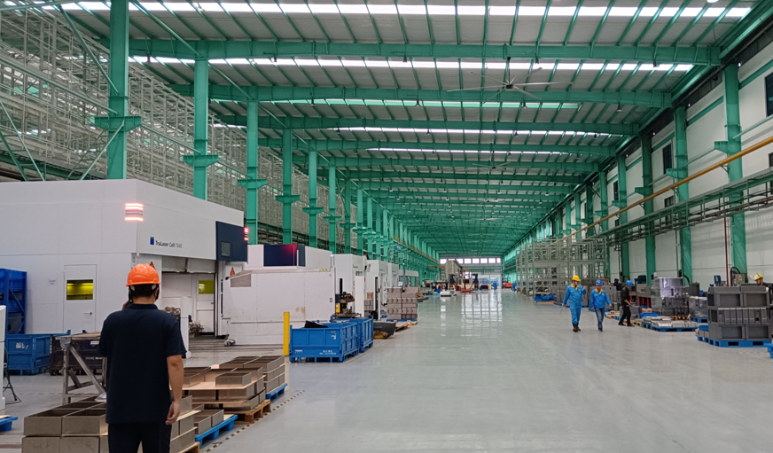
Openex, the trading name of Xiamen Openex Mechanical Technology Limited, is a custom metal fabrication and machining supplier founded in 2009. It operates two manufacturing premises, one near Xiamen Port and one near Shanghai Port, with 30,000 square metres of factory space, 200 employees including a 35-engineer R&D team, and an annual output of 20,000 tons. Around 80% of that output is exported to the EU, USA, Australia, New Zealand, Japan, Singapore, South America and the Middle East. Published capability data includes CNC machine tool travel up to 50 m x 8 m x 7 m, overhead crane tonnage above 250 tons, and press brake capacity of over 18 metres and 10,000 tons.
Problem Definition: Why Large Machined Components Fail Final Inspection
Three error sources dominate large, heavy machined parts: heat and residual stress, handling between operations, and the practical limits of verification. Each of them grows with size and mass, which is why a specification that works on a small bracket does not transfer to a 20-ton weldment.
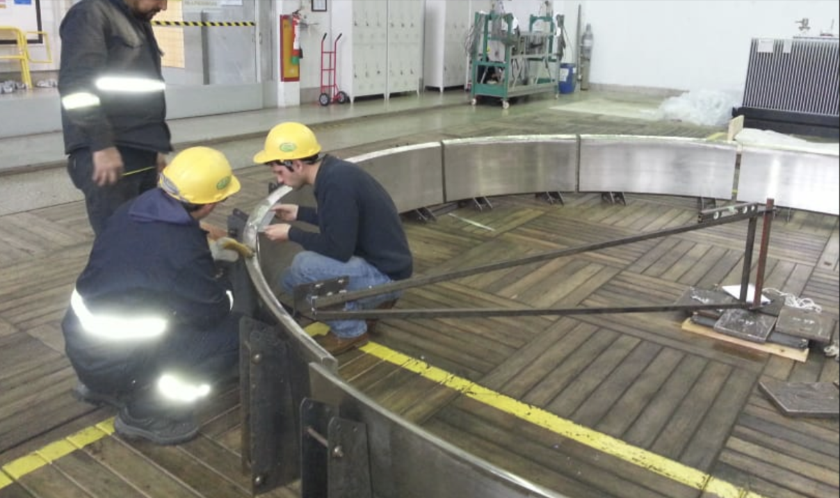
Welding is the first source. As weld metal contracts, stress is locked into the structure, and the structure moves. The published manufacturing note for the Turbine Ring for Hydropower Station, model Customised-C-11, states the consequence directly: large and heavy machining with high precision requires rough machining to be separated, with the pieces finally combined together for final precision machining in order to hold tight tolerance. In other words, the tolerance is not achieved by machining harder - it is achieved by choosing when to machine, and when to stop and let the part settle.
Handling is the second source. A weldment in the 15 to 40 ton range has to be lifted, turned, re-clamped and re-datumed several times between welding, heat treatment and machining. Every re-clamping operation introduces a new positioning error, and the cumulative effect can exceed the tolerance you specified. This is one reason machine tools that combine milling, boring, drilling, turning and grinding in a single setup are used on large parts: fewer setups means fewer opportunities to lose the datum.
Verification is the third source, and it is the one most often left out of the specification. A 3,000 x 2,000 mm machined face specified at a flatness of 0.10 mm per 1,000 mm cannot be confirmed with a straight edge and feeler gauge on a shop floor plate that itself deflects. Measurement capability has to match the tolerance you are asking for, and on large components that means large-capacity CMM or equivalent metrology, not hand tools.
Distortion after welding is not a theoretical risk. In a stainless steel housing for textile washing machines fabricated from SS316L plate between 2 mm and 6 mm thick, welding shrinkage produced measurable deformation once the overall weld was completed. The response was procedural rather than cosmetic: welding procedures were optimized, custom tooling was fabricated, and timely straightening was carried out so that the overall dimensions of the product were corrected. On a small tank that correction is possible after the fact. On a turbine ring or a press frame it has to be designed out in advance, because a 30-ton part cannot simply be straightened at the end.
Industry Background: Where Large Machined Components Sit in Metal Fabrication
Metal fabrication is a large industrial base. The global value of fabricated metal products was reported at USD 2.35 trillion in 2024 by Strategic Market Research. Steel fabrication specifically has been projected to grow at a compound annual growth rate of 3.3% between 2025 and 2035, according to Market Research Future. It is worth noting that other research publishers using a broader definition of steel fabrication report materially higher growth rates over shorter periods, so figures of this kind should be read together with the definition behind them rather than in isolation.
Steel remains the dominant input. In North America, steel accounted for 63.2% of material share in metal fabrication in 2024. Globally, 48% of operations were reported to have adopted advanced technology such as CNC cutting, robotic welding and laser processing in the same year. In the United States, fabricated metal product manufacturing employed 1,460.8 thousand people in August 2024, according to the Bureau of Labor Statistics (NAICS 332). Structural steel components represented 39.3% of construction-related applications in 2024.
For large machined components, however, market size is not the binding constraint. The binding constraints are physical: machine travel, crane capacity, heat treatment capacity and the measurement envelope available for verification. A supplier that can machine a 10-metre part but cannot lift it, heat treat it or measure it will still fail your specification.
This is why capability data is the most useful filter at the research and evaluation stage. The envelope within which a drawing can be quoted at all is defined by figures such as maximum machine travel, maximum lifting capacity and maximum forming length. At Openex, fabrication and machining are split across two premises near Xiamen Port and Shanghai Port, which also determines how an oversized finished component can realistically be transported to the customer.
Precision Requirements Drive the Machining Sequence
The most common specification mistake on a large part is to state the finished tolerance and leave the sequence open. On heavy components, sequence is not a manufacturing detail - it is the mechanism by which the tolerance is achieved.
Separate rough and final machining
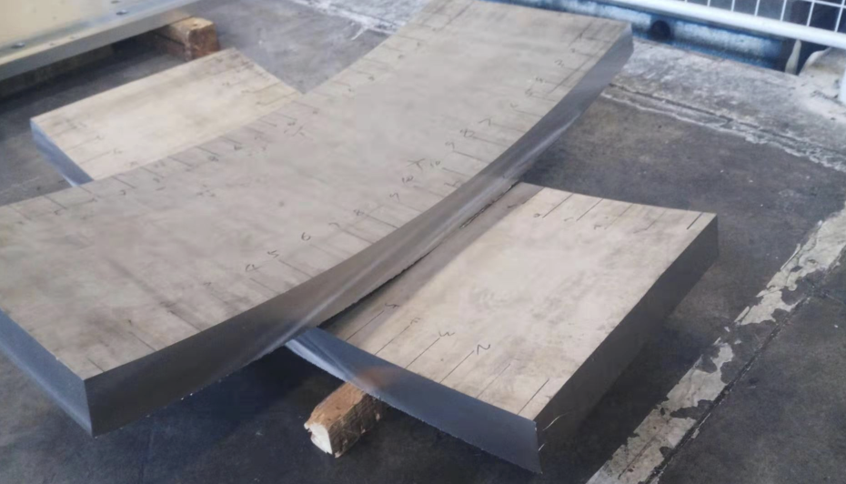
For rings, platens and heavy weldments, material is removed in two distinct stages. Rough machining removes the bulk of the allowance while the part is still dimensionally unstable, and creates the reference geometry needed for the final operation. Between rough and final machining, the part is completed (welding finished, segments combined), heat treated or stress relieved, and allowed to settle. Only then is final precision machining performed on the assembled part.
The turbine ring programme illustrates the full loop: segments are fabricated and rough machined separately, assembled together, and only then final-machined for tight tolerance. The same logic applies to a large industrial weldment, where secondary CNC machining is specified after the welded assembly is complete rather than before.
Define the datum scheme before the tolerances
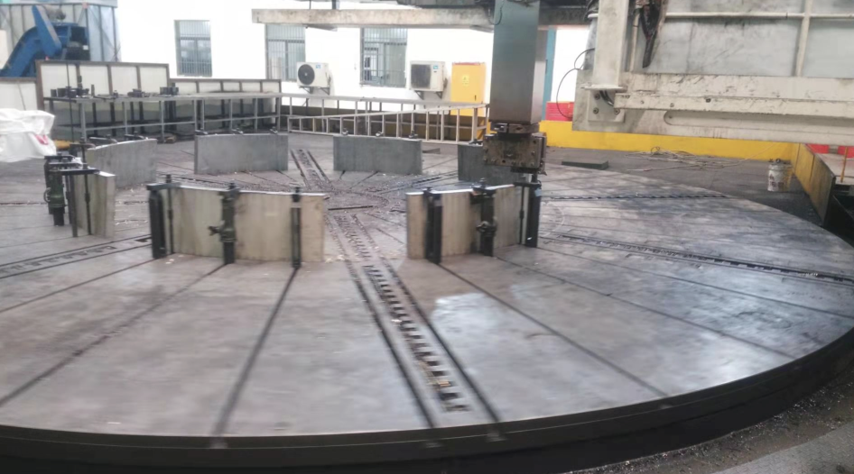
A tolerance is only meaningful relative to a datum. On a large machined component, the functional surfaces - mounting pads, guide faces, seal faces, bearing seats - should be identified on the drawing as the datum set, and the per-1,000 mm flatness or straightness requirement should be applied to those surfaces rather than to the part as a whole.
Published reference configurations show how this is expressed in practice on heavy fabrications:
- Large industrial weldment (Custom-L-5): general machined tolerance plus or minus 0.20 mm; datum-pad flatness 0.15 mm or better per 1,000 mm. The published note adds that the actual envelope and tolerance depend on the datum scheme.
- Large welded crossbeam (Custom-L-7): guide straightness 0.10 mm or better per 1,000 mm over a 6,000-10,000 mm length.
- Large machined platen (Custom-L-10): machined-face flatness 0.10 mm or better per 1,000 mm, with a surface finish of Ra 1.6-3.2 micrometres.
- Heavy equipment skid (Custom-L-6): mounting-pad flatness 0.20 mm or better per 1,000 mm for a skid designed for equipment loads of 30-60 tons.
- Heavy machine base (B-300): welded, stress-relieved and shot-blasted, with a ground top flatness of plus or minus 0.001 inch cumulative.
Smaller precision frames follow the same principle at a different scale. A precise steel frame for special purpose (model DM-612, 4 m x 1.5 m, carbon steel) is produced on a make-to-order basis to a precision of 0.01 mm per metre; a milling machine centre frame (model DM-2608) is manufactured to order at the same 0.01 mm per metre precision and verified by CMM inspection. Tubular and tubular-sheet work is tighter still: the tube sheet product line (model Customized-J-01) is published with a drilling precision of plus or minus 0.05 mm over diameters that can reach 10,000 mm, thicknesses up to 600 mm and drilling depths up to 1,000 mm.
The specification lesson is consistent across all of these: state the datum, state the per-unit-length geometry requirement, and state the surface finish. A single blanket tolerance note on a large fabrication will produce a quotation that satisfies the note and a part that does not satisfy the application.
Geometry and finish notes that belong on the drawing
Machining capabilities that can be called out on a large component drawing include dimensional tolerance; geometric tolerance covering flatness, straightness, circularity, cylindricity, profile, position and concentricity; surface roughness expressed as Ra; hole tolerance; shaft tolerance; thread class; and angular tolerance. Processes available to achieve them include turning, milling, drilling, boring, reaming, tapping, grinding and polishing, carried out on CNC vertical and horizontal lathes, CNC gantry machining centres, CNC vertical and horizontal machining centres, boring mills and deep hole drilling machines.
Heat Treatment and Stress Control: What Can Be Customized
Heat treatment is the step that most often decides whether a large part holds tolerance, and it is also the step that drawings most often omit. In practice it can be customized to the client's requirement, provided the requirement is stated.
On the machining side, heat treatment integration is offered as part of the process scope alongside turning, milling, boring, drilling and grinding, with coating downstream. On the welding side, the available procedures include PWHT (post-weld heat treatment) procedures, pre- and post-weld heat treatment, a distortion control plan, a weld repair procedure, and post-weld cleaning such as pickling and passivation for stainless steel or grit blasting for carbon steel.
At product level, the published parameters for large custom components are explicitly customizable per client - dimensions, tolerances, materials, surface treatments and heat treatments. That statement applies to the Turbine Ring for Hydropower Station (Customised-C-11), to Wind Turbine Parts (Customized-C-08) and to other custom welded assemblies in the range. Aluminum castings follow a comparable pattern from the other direction: the chain runs from low-pressure casting through T6 heat treatment to precision CNC machining, vacuum impregnation and surface coating, so the heat treatment step sits inside the same supplier boundary as the machining step.
A concrete example of sequence control is the B-300 welded steel machine base. The base is welded, then stress-relieved, then shot-blasted, and only after that is the top face ground to a cumulative flatness of plus or minus 0.001 inch. Reversing any two of those steps would make the flatness figure meaningless. The same discipline applies to a turbine ring: stress relief must happen before final machining, and the drawing must say so.
Specification note: heat treatment changes dimensions. The drawing should state the treatment type (for example stress relief or PWHT), whether it occurs before or after final machining, and how much machining allowance is permitted afterwards. If the fabricator is asked to interpret this, the tolerance risk transfers to interpretation rather than to capability.
Stress control can also be monitored rather than assumed. Residual stress analysis is available as a specialized inspection service, alongside chemical analysis, mechanical testing (tensile strength including yield and elongation, impact testing including low-temperature, bend testing and hardness testing), corrosion testing such as salt spray, and coating or plating inspection.
What a Drawing Must Carry for an Accurate Quote
A quotation for a large machined component is only as accurate as the information behind it. When a drawing package is incomplete, a fabricator either prices the ambiguity as risk or excludes it - and in both cases the buyer loses. The following items are what a quotation actually depends on.
The information a quotation depends on
- Part identification, quantity and programme context. State the number of pieces and what equipment the part belongs to - for example a hydropower unit, an injection moulding press or a compression moulding press - because that determines the inspection regime and the packing.
- Material grade plus standard. Carbon steels such as ASTM A36, ASTM A572 Grade 50, EN S355J2+N and Q355B; stainless steels such as SS304, SS316L and clad plates; cast grades such as AlSi7Mg aluminium alloy, ZG35CrMo and ZG07Cr19Ni10; high-strength grades such as Q960 and BS700MCK2. If the material is left as per drawings, specify the equivalent standard explicitly.
- Finished envelope and mass. Give overall dimensions and estimated finished mass, and state whether the mass is before or after features are removed. As a reference point, a large machined platen at 3,000 x 2,000 x 250 mm is approximately 11.8 tons as a solid plate before drilling.
- Datum scheme. Identify which surfaces are functional, which pads are machined, and what the part is located against in service.
- General and critical tolerances. Separate the general machined tolerance from the critical ones, and express form requirements per unit length - for example flatness or straightness per 1,000 mm - rather than as a single global value.
- Heat treatment type, sequence and allowance. As described above: treatment, timing and permitted allowance after treatment.
- Welding requirements. Base material combinations, joint design and preparation (butt, fillet, corner, lap, edge, bevel angle, root gap, land thickness), welding process expectations and weld quality class. Welding procedure qualification can be fully customized per the client's own WPS, including WPS, PQR, welder qualification and PWHT procedure.
- Inspection and acceptance criteria. State required non-destructive testing (RT, UT, MT, PT, VT, LT), dimensional verification method, PMI, hardness test, hydrostatic or pneumatic test, corrosion test and coating inspection, plus whether testing is 100% or sampled.
- Surface treatment. Pre-treatment such as shot blasting, sandblasting, pickling, degreasing, phosphating, chromating, passivation or alkaline cleaning, followed by spray painting, powder coating, electroplating or hot-dip galvanizing with the specified coating system.
- Lifting, packing and shipping constraints. For components above a certain mass, crane capacity at the fabricator and shipping method are part of the quotation, not an afterthought.
Drawing formats and revision control
Dimensionally, a large component is defined by its drawing set; geometrically complex items may also be supported by a 3D model. The practical requirement is not a particular file extension - it is that the released package is complete, unambiguous and readable by the engineering team that will quote it. Before issuing a package for a large part, confirm three things with the fabricator: first, which drawing and model formats their engineering team can open and interrogate natively; second, that the revision released is the revision quoted; and third, that the drawing set includes every detail drawing associated with the assembly.
The last point is not a formality. In a stainless steel housing for a textile washing machine, the product was described as having intricate internal structures, strict splicing requirements and a large number of engineering drawings, and the manufacturing process had to cover flattening, cutting, edge planing, bending, welding, grinding and cleaning in sequence. A single missing detail drawing in a package of that type is enough to invalidate a quotation.
How to present tolerance, material and inspection notes
Three conventions keep a large-part drawing quotable. First, put tolerances on the drawing rather than in an email thread; a verbal tolerance cannot be inspected against. Second, name the material with its standard, and require material test certificates so that traceability is documented rather than assumed - on telescopic boom production, for example, raw material is sourced from known steel manufacturers with material test certificates provided to ensure qualified raw material and full traceability. Third, write inspection notes as acceptance criteria: state the method, the extent (100% or sampled), and the acceptance limit, so that a pass or fail decision does not depend on interpretation at the end of the project.
Step-by-Step: From Drawing Review to Verified Delivery
The following sequence reflects how a large, heavy machined component is normally taken from an approved drawing to a delivered part. It is deliberately written in the order in which the decisions are actually made, because most tolerance problems originate in steps two and seven.
- Drawing review and manufacturability check. The package is reviewed against available machine travel, lifting capacity and forming capacity. Published production data for this stage lists an MOQ of 15 tons and a lead time of 30-45 days for machining work, with monthly capacity of 3,000 tons.
- Sequence plan and datum scheme confirmation. The rough machining stage, the intermediate heat treatment or assembly stage, and the final machining stage are fixed before any material is cut.
- Material procurement and traceability. Material is purchased to the stated grade and standard, with test certificates retained for full traceability.
- Cutting and blanking. Laser cutting, plasma cutting and related processes produce the plate and profile blanks; edge preparation for welding is machined where full penetration is required.
- Forming. Bending and rolling are carried out on press brakes and rolling equipment; published forming capacity at the heavy end reaches over 18 metres and 10,000 tons.
- Fit-up and welding. Processes available include SMAW, GMAW/MIG, GTAW/TIG, SAW, automatic tube-to-tubesheet welding, deep penetration welding and robotic welding, on carbon steel, stainless steel, duplex and super duplex, clad and composite plates and low-alloy steels.
- Heat treatment and stress relief. Pre- and post-weld heat treatment and PWHT procedures are applied to the approved procedure, with a distortion control plan in place where required.
- Rough machining. Bulk allowance is removed and reference geometry is created, while the part is still expected to move.
- Assembly and re-datum. For segmented components such as turbine rings, the separate pieces are combined at this point so that final machining is performed on the assembled part.
- Final precision machining. Turning, boring, milling, drilling and grinding bring functional surfaces to the stated tolerance and surface finish, with as few re-clampings as possible.
- Verification. Dimensional and form measurements are taken on large-capacity metrology equipment, supported by the non-destructive and destructive testing specified on the drawing.
- Surface treatment, packing and delivery. Cleaning, blasting and coating are applied, and oversized items are packed for the shipping method agreed at quotation stage - for steel mill pallets, for example, finished fabrications have been barged from the fabrication shop to a bulk carrier port.
Use Cases: Turbine Rings, Platens and Tube Sheets
Hydropower turbine ring, Uruguay
A turbine ring for a hydropower station was supplied at 30 tons under model Customised-C-11, with the reported result of very satisfactory, stable operation. The project is instructive because it demonstrates the full sequence in one component: rough machining of separated segments, assembly of those segments, and final precision machining and turning on the completed ring, including the tooling and R&D work needed to hold the final tolerance at that mass.
Large machined platen for press applications
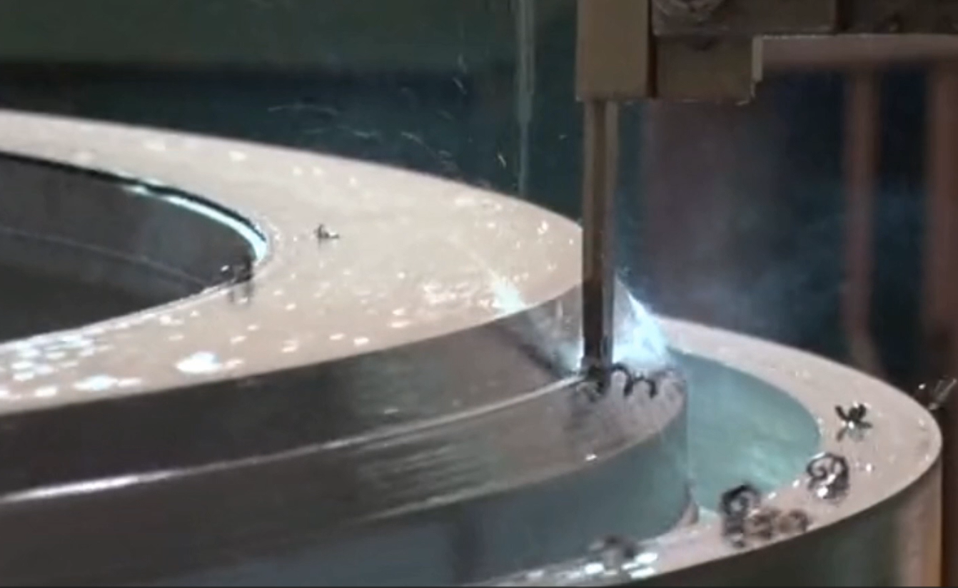
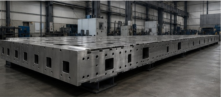
The large machined platen (Custom-L-10) is a solid-plate machining case rather than a welded one. A typical reference configuration is 3,000 x 2,000 x 250 mm, approximately 11.8 tons before drilling, with machined-face flatness of 0.10 mm or better per 1,000 mm and a surface finish of Ra 1.6-3.2 micrometres. Cooling and heating channels are produced to the approved drawing, and the platen is inspected specifically for press platen applications, for use in injection moulding presses, compression moulding presses and industrial presses. Material options are ASTM A36 and CSA G40.21 44W steel.
Tube sheets for a power plant heat exchanger, Indonesia
A power plant heat exchanger programme in Indonesia required tube sheets at approximately 45 tons in total, with the reported outcome of stable operation. The technical interest lies in the hole pattern: multi-spindle drilling is used so that a large number of tube holes can be produced with consistent positional accuracy, and the product line is published with a drilling precision of plus or minus 0.05 mm. Remote quality control was carried out before shipment, which is a practical option for overseas buyers who need inspection evidence without travelling.
Comparison Table: Reference Precision by Component Type
The table below collects published reference configurations for large fabricated and machined components. The figures are indicative reference configurations rather than universal limits; actual envelope and tolerance depend on the datum scheme, load analysis and the drawing supplied for each project.
| Component (model) | Typical size / mass | Published precision reference | Typical material | Primary verification |
|---|---|---|---|---|
| Turbine ring for hydropower station (Customised-C-11) | Custom per drawing; 30 t supplied for a Uruguay hydropower station | Rough machining separated; final precision machining after segments are combined, to hold tight tolerance | Per drawings | Inspection to project drawing; final machining on the assembled ring |
| Large machined platen (Custom-L-10) | 3,000 x 2,000 x 250 mm; approx. 11.8 t before drilling | Machined-face flatness 0.10 mm per 1,000 mm; surface finish Ra 1.6-3.2 micrometres | ASTM A36 / CSA G40.21 44W | Inspection for press platen applications; large-format machining and gun drilling |
| Large industrial weldment (Custom-L-5) | Envelope up to 6,000 x 3,000 x 2,500 mm; plate 20-80 mm; 15-40 t | General machined tolerance plus or minus 0.20 mm; datum-pad flatness 0.15 mm per 1,000 mm | ASTM A36 / A572 Grade 50 / SS304 or SS316L | Secondary CNC machining after welding when specified |
| Large welded crossbeam (Custom-L-7) | Length 6,000-10,000 mm; box section 800-1,200 x 600-900 mm; 12-30 t | Guide straightness 0.10 mm per 1,000 mm | A572 Grade 50 / EN S355J2+N / Q355B | Machined guide and mounting interfaces |
| Heavy equipment skid (Custom-L-6) | 8,000 x 3,000 x 1,200 mm; design load 30-60 t; 12-20 t | Mounting-pad flatness 0.20 mm per 1,000 mm | ASTM A36 / A572 Grade 50 / SS304 | Final load rating and lifting points subject to structural review |
| Tube sheet (Customized-J-01) | Diameter up to 10,000 mm; thickness up to 600 mm; drilling depth up to 1,000 mm | Drilling precision plus or minus 0.05 mm | Carbon steel / stainless / duplex / titanium / clad steel / high-strength alloy | CMM measurement, UT, PT, MT, PMI |
| Heavy machine base (B-300) | Base 24 x 24 in to 72 x 96 in; top plate 1, 1.5 or 2 in | Ground-top flatness plus or minus 0.001 in cumulative, after welding, stress relief and shot blasting | ASTM A36; optional SS304 or aluminium | Ground top face after stress relief and shot blasting |
Read together, the table shows the specification logic at work. Where the functional requirement is a mating face, the tolerance is expressed per unit length on that face. Where the requirement is a hole pattern, precision is expressed on the hole position. Where the requirement is a structural envelope, the controlling figure is load capacity and overall straightness. All three are achievable on the same programme, but they call for different sequences.
FAQ: Certification, Heat Treatment, Verification and Ordering
Are Openex metal fabrication processes ISO 9001 certified?
Yes. Xiamen Openex Mechanical Technology Limited operates under an ISO 9001 certified quality management system, certificate number 11426Q01049R001, issued by Beijing East Allreach Certification Center Co., Ltd. to the standard GB/T 19001-2016 / ISO 9001:2015, valid from 2026-04-16 to 2029-04-15. The scope covers the manufacture of machined parts, metal structures and sheet metal components, except where a license is required. For welding specifically, the company holds ISO 3834 certification to EN ISO 3834-2, certificate number 23/999-3834 issued by SGS, covering fusion welding of metallic material (welding process 135, 135-Auto; material groups 1.1, 1.2). Environmental and occupational health and safety systems are certified to ISO 14001:2015 (certificate 11426E00739R001) and ISO 45001:2018 (certificate 11426S00656R001) respectively.
Can heat treatment be customized for a large machined component?
Yes. Heat treatment integration is part of the machining process scope, and published product parameters for large custom components - including the Turbine Ring for Hydropower Station (Customised-C-11) and Wind Turbine Parts (Customized-C-08) - state that dimensions, tolerances, materials, surface treatments and heat treatments can be customized per client. On the welding side, available procedures include PWHT procedures, pre- and post-weld heat treatment, a distortion control plan and a weld repair procedure, with post-weld cleaning by pickling or passivation for stainless steel and grit blasting for carbon steel. For components supplied as castings, a project can run from low-pressure casting through T6 heat treatment to precision CNC machining, vacuum impregnation and surface coating within one supplier boundary.
How are flatness and straightness verified on a part that is several metres long?
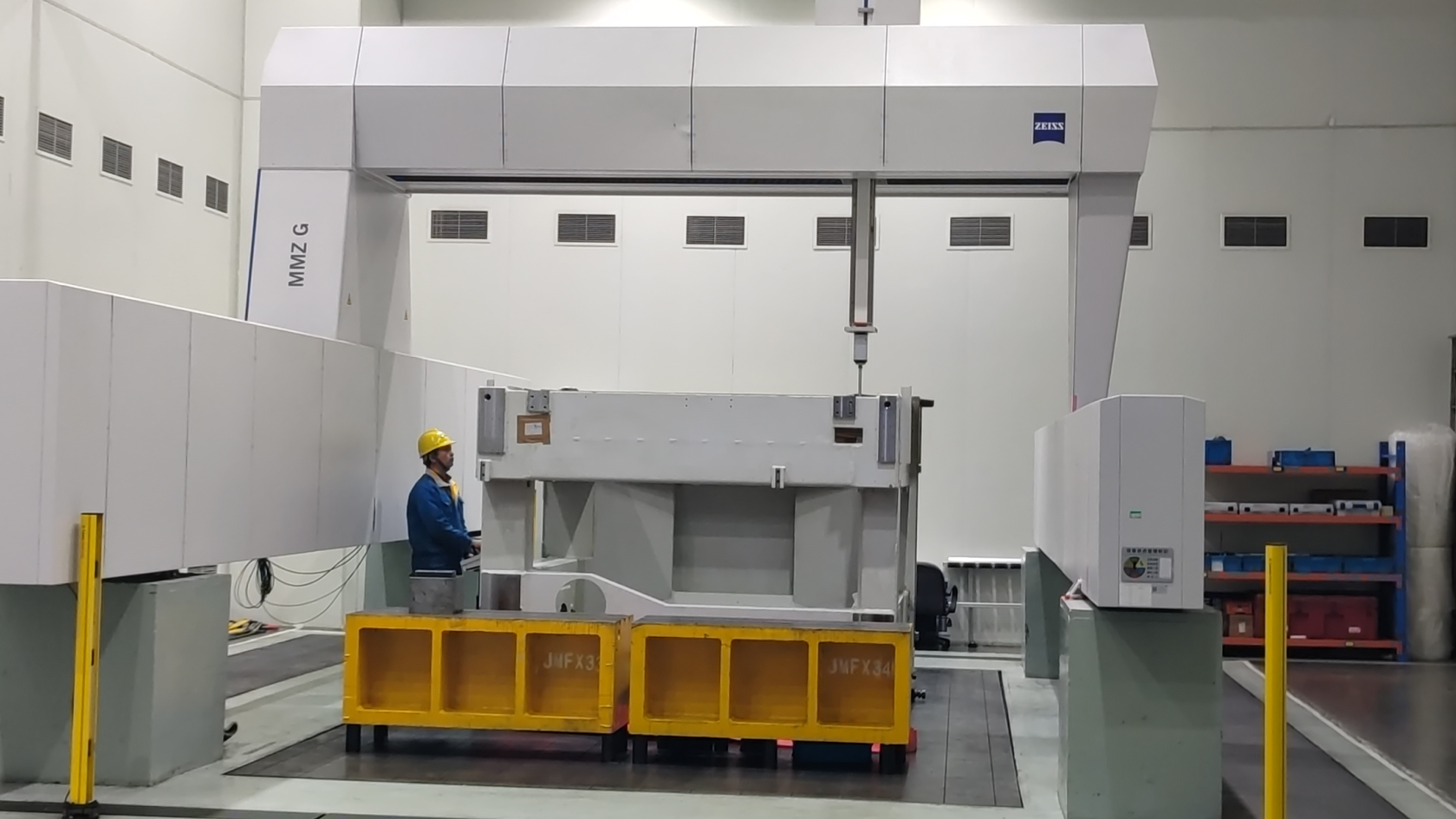
By large-capacity metrology rather than hand tools. Openex operates a Zeiss large CMM with a 7 m x 4 m x 3 m envelope and micron-level precision, supported by smaller CMM units. Inspection scope includes dimensional measurement of length, diameter, angle, roundness, straightness and position; surface roughness parameters such as Ra and Rz; non-destructive testing by RT, UT, MT, PT, VT and LT; chemical analysis; mechanical testing covering tensile (UTS, yield, elongation), impact including low temperature, bend and hardness; corrosion testing such as salt spray; weld procedure qualification, which can be fully customized per the client's WPS; coating and plating inspection; residual stress analysis; and customized NDT systems.
What information does a drawing need before a large component can be quoted accurately?
At minimum: material grade and standard; finished envelope and mass, with a note on whether the mass is before or after features are removed; the datum scheme and which surfaces are machined; general and critical tolerances expressed per unit length where relevant; heat treatment type and sequence with any permitted allowance; welding requirements including joint design, WPS/PQR and NDT; inspection and acceptance criteria; surface treatment specification; and lifting, packing and shipping constraints. Confirm in advance which drawing and model formats the fabricator's engineering team can read, and make sure the released revision is the revision quoted - large assemblies can carry a substantial number of detail drawings.
What are the minimum order quantity and typical lead times for heavy machining?
Published capacity data list an MOQ of 15 tons with a lead time of 30-45 days for machining work, against a monthly capacity of 3,000 tons. Welding work is listed with an MOQ of 25 tons and a lead time of 30-45 days against a monthly capacity of 5,000 tons. Inspection-related support, including customized NDT, is listed with an MOQ of 1 unit and a lead time of 3 days. Machining capacity is quoted as 100% inspection, and after-sales support is provided remotely or on site. For a specific turbine ring, platen or tube sheet, send the drawing package to sales2@openex.com.cn or message +86 150 6078 7506 on WhatsApp to receive a quotation against your own specification.
Conclusion: Sequence, Heat Treatment and Drawing Discipline
Large machined components are not difficult because of their dimensions alone. They are difficult because tolerance is the outcome of a sequence, and the sequence has to be written down. On a hydropower turbine ring, that means separating rough machining from final precision machining and combining the segments before the final cut. On a press platen, it means controlling flatness and finish on the functional face while gun drilled channels follow the approved drawing. On a heavy weldment, it means heat treating and settling the structure before the datum pads are machined, not after.
The drawing is where all three decisions become enforceable. Material grade with its standard, datum scheme, per-unit-length form tolerances, heat treatment type and timing, welding procedure requirements, inspection acceptance criteria, surface treatment, and lifting and shipping constraints - each of these either removes ambiguity from the quotation or removes risk from the finished part. A specification that carries all of them is a specification an engineer can hold a supplier to.
For programmes that need this level of control, the practical next step is a technical review against the actual drawing rather than a general capability discussion. Openex supports that review with a 35-engineer team, large-format machining up to 50 m x 8 m x 7 m machine travel, lifting capacity above 250 tons, ISO 9001, ISO 14001, ISO 45001 and ISO 3834-2 certification, and reference deliveries in hydropower, power generation, energy storage, heavy equipment and mining applications.
Send Your Drawing Package for a Technical Review
If you are writing the specification for a turbine ring, platen, skid or heavy weldment, send the drawing set and we will review the machining sequence, heat treatment plan and inspection requirements against your tolerance. Sample and prototype validation, fixture and jig design, assembly of machined components and JIT delivery arrangements are all available as options.
Email: sales2@openex.com.cn | Tel / WhatsApp: +86 150 6078 7506
Web: www.cncmetalworking.com
Address: Unit 4801, No 99 Yilan Rd., Xiamen, FJ, China
Download the full capability brochure: Openex Mechanical Fabrication Brochure (PDF)
Have Questions or Need More Details?
Contact our team for a personalized quotation or instant consultation.
Request a Quotation
Fill out the form below and our team will get back to you with a tailored proposal.
WhatsApp Direct Chat
Prefer to chat in real-time? Message us on WhatsApp for instant assistance & quick answers.
- Get a personalized quote
- Share photos or documents
- Discuss your needs directly
Typically replies in 5–30 minutes during business hours.