Welded vs. Welded and Machined Steel Chassis: A Buyer's Comparison
Welded vs. Welded and Machined Steel Chassis: A Buyer's Comparison
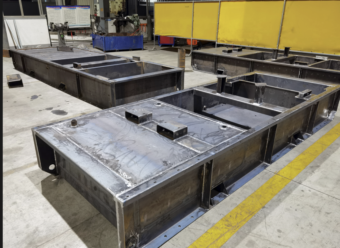
Base frame and base tank welded and machined by Openex for a diesel generator set, where the diesel engine and the generator sit on one steel chassis that must hold high coaxiality.
For most machinery, a welded steel chassis is the correct and most economical answer. For a chassis that has to hold a diesel engine and its generator on one alignment, or carry a 30-ton container every day on a travelling machine, welding alone is usually not enough. Those chassis are welded first and then post-machined, so that mounting faces, bores and hole patterns are cut after welding distortion has already taken place.
This comparison is written for importers, procurement managers and engineers who are choosing between a welded-only steel chassis and a welded-and-machined steel chassis, and who need to know where the boundary sits, what to inspect, and how cost and lead time change. Two production programs built by Openex fabrication (Xiamen Openex Mechanical Technology Ltd) define that boundary in practice: diesel generator (DG) base frames that have been in stable operation for 20 years, and AGV steel chassis that have been running for more than four years.
The short answer: choose welded-only when the interfaces the chassis carries are forgiving. Choose welded and machined when the chassis is responsible for the alignment of rotating equipment, for coplanar mounting pads, or for hole patterns that must match a machined counterpart.
What Welded-Only and Welded-and-Machined Actually Mean
Two different production routes are often quoted under one phrase, sheet metal fabrication, but they deliver different things. A welded-only chassis follows a fabrication route: laser cutting, bending or roll forming, punching and stamping, welding, then surface preparation and finishing such as shot blasting, painting, powder coating or hot-dip galvanizing. Its dimensions are held by fixtures, fit-up quality and welding sequence.
A welded-and-machined chassis follows the same fabrication route and then adds a machining stage after welding: turning, milling, drilling, boring, reaming, tapping and grinding, followed by re-inspection. Only the interfaces that need it are machined, typically the mounting pads, bores, guide surfaces and hole patterns.
The reason the second route exists is thermal. Every weld deposits metal that contracts as it cools, so geometry that was true during fit-up moves slightly afterwards. On a support frame or a guardrail that movement is harmless. On a base carrying two rotating assemblies it is not: the engine and the generator must sit on one datum line, and any angular error becomes a coupling alignment problem at commissioning and a wear problem in service.
Post-weld machining therefore does four jobs. It establishes coaxiality between the mounting interfaces of two or more components. It makes mounting pads coplanar in one setup. It places holes to match a counterpart that is already machined. And it produces guide or slide surfaces with controlled straightness and surface roughness.
A short decision rule
Specify welding plus post-machining when any of the following is true: two rotating assemblies must share one datum line; mounting pads for engines, gearboxes, pumps or rails must sit in a defined plane; hole patterns must match an already-machined counterpart; or the chassis itself is a moving load path in service. If none of these apply, welded-only fabrication is normally the right and lower-cost choice.
Why Splitting Fabrication and Machining Creates Risk
In many supply chains, heavy steel fabrication and heavy precision machining sit in different companies, often in different cities or countries. The buyer takes delivery of the welded part from one vendor and ships it to another for machining. Three risks follow, and they are usually visible only after the first article is late.
- Datum loss. The datums and setup references controlled in the welding shop no longer exist by the time the part reaches the machining partner, so the datum must be re-established from machined or cast surfaces that may themselves be rough.
- A responsibility gap. If the welded chassis arrives outside the agreed machining allowance, neither the fabricator nor the machinist owns the complete tolerance chain, and the schedule absorbs the discussion.
- Extra handling. Every move of a heavy chassis is a cost and a risk, and parts in the 10-ton class and above are not easy to re-fixture.
Openex operates both capabilities inside one company. It runs two manufacturing premises, one near Xiamen Port in Fujian and one near Shanghai Port in Jiangsu, and it was founded in 2009. Today the company reports 30,000 square metres of manufacturing space, around 200 employees, an annual output of 20,000 tons and an engineering team of 35 people, with about 80% of output exported to the EU, USA, Australia, New Zealand, Japan, Singapore, South America and the Middle East. Its heavy capacity includes overhead cranes over 250 tons, bending machines over 18 m and up to 10,000 tons, and CNC machine tools with travel up to 50 m by 8 m by 7 m.
Capability data for the two production units that build chassis shows the scale and the timing a buyer should plan for. The welding unit is quoted at a monthly capacity of 5,000 tons with 100% testing and a 30-45 day lead time. The machining unit is quoted at a monthly capacity of 3,000 tons with 100% inspection and a 30-45 day lead time. Surface preparation and coating add a further stage, quoted at 3,000 units per month and a 45-day lead time.
How a Welded and Machined Steel Chassis Is Built at Openex
Welding: procedure-controlled rather than operator-controlled
Openex welds carbon steels, stainless steels, duplex and super duplex grades, clad and composite plates and low-alloy steels, using SMAW, GMAW/MIG, GTAW/TIG, SAW, automatic tube-to-tubesheet welding, deep penetration welding and robotic welding. Joint design covers butt, fillet, corner, lap and edge joints, with bevel angle, root gap and land thickness defined on the drawing. Documentation includes welding procedure specifications, procedure qualification records, welder qualification and post-weld heat treatment procedures.
For long or heavily restrained chassis, a distortion control plan and pre- or post-weld heat treatment are applied before machining. Reducing residual stress before the cutting stage is what keeps a machined interface flat after the part is released from the fixture. Post-weld cleaning is matched to the material: pickling and passivation for stainless, grit blasting for carbon steel.
Where repetition matters, 6-axis industrial welding robots are used. The units in service are quoted at plus or minus 0.05 mm repeat positioning accuracy, are able to run continuously, hold trajectory accuracy in the range of plus or minus 0.2 to 0.5 mm at a consistent welding speed of 5 to 50 mm per second, and use built-in seam tracking to correct clamping deviation. On a chassis ordered in batches of hundreds, that repeatability is what keeps the machining allowance predictable.
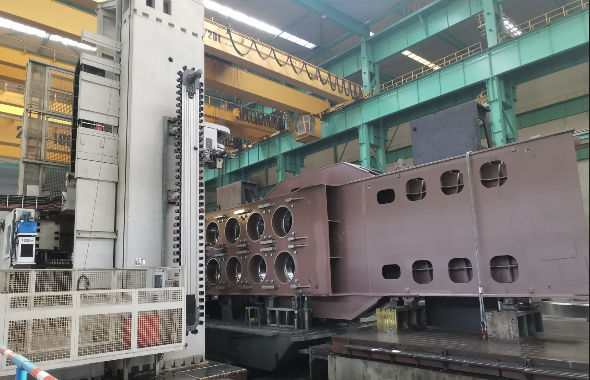
Large CNC machining carried out after welding fabrication, so that mounting interfaces are cut in their final position rather than being left to the welded assembly.
Machining after welding: one setup wherever the machine envelope allows
The machining stage covers turning, milling, drilling, boring, reaming, tapping, grinding and polishing on CNC vertical lathes, CNC horizontal lathes, gantry machining centres, vertical and horizontal machining centres, boring mills, deep-hole drilling machines and laser cutting equipment. The equipment that decides whether a chassis can be machined in one setup includes:
- A double-gantry machining centre with a 7-axis, 5-linkage control system that completes milling, boring, drilling, turning and grinding operations in a single setup, which removes the repeated positioning errors caused by multiple clamping.
- A PAMA Speedram 180 CNC floor-type boring and milling machining centre, with travels of X 4,000-6,000 mm, Y 4,000-6,000 mm, Z 1,200 mm and W 1,000 mm, giving a total Z plus W travel of 2,200 mm.
- A Wuzhong single-column CNC turning and milling machine, model CKX53220 x 65/600, with a maximum machining diameter of 22 m, a maximum workpiece load of 600 t and a maximum workpiece height of 6.5 m.
- Vertical machining centres such as the EATRON M1100, quoted at plus or minus 0.010 mm positioning accuracy and plus or minus 0.003 mm repeatability, for the smaller precision components that mount on the chassis.
Controlled characteristics include dimensional tolerance; geometric tolerance in flatness, straightness, circularity, cylindricity, profile, position and concentricity; hole tolerance and shaft tolerance; thread class; angular tolerance; and surface roughness expressed in Ra.
Inspection: the part of the quotation buyers should read first
Weld inspection uses visual inspection and non-destructive testing methods including RT, UT, MT, PT and LT, with optional TOFD and phased array, hardness testing and hydrostatic or pneumatic testing. Destructive testing covers chemical analysis of element composition, tensile testing of ultimate tensile strength, yield and elongation, impact testing including low temperature, bend testing and hardness testing, plus corrosion testing by salt spray. Dimensional and visual inspection covers length, diameter, angle, roundness, straightness and position, with surface roughness measured in Ra, Rz and other parameters. Specialised inspection includes residual stress analysis, coating and plating inspection, and customised NDT systems.
Final geometry can be verified on a Zeiss large coordinate measuring machine with 7 x 4 x 3 m capacity and micron-level precision, with smaller CMMs available for smaller components. For high-volume small metal parts, Openex also builds visual inspection machines, because 100% machine checking is more trustworthy than manual inspection on repeat quantities.
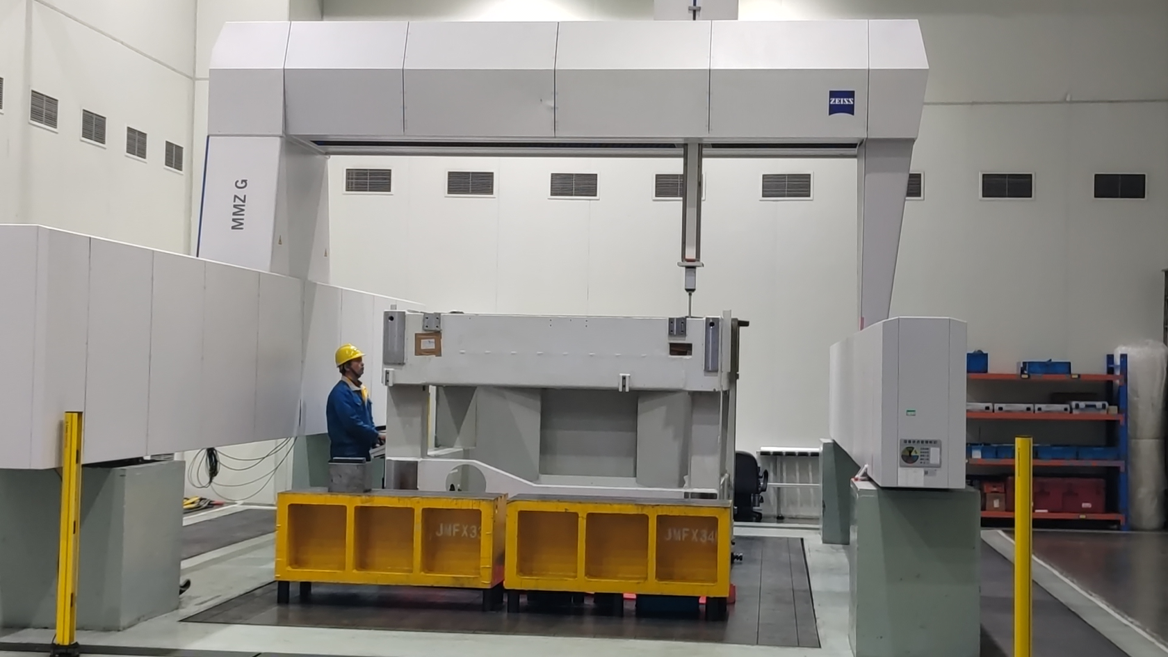
A Zeiss large CMM with 7 x 4 x 3 m capacity and micron-level precision, used to verify coaxiality, pad flatness and hole position after post-weld machining.
Welding certification
Welding is governed by an ISO 3834-2 system: certificate 23/999-3834, issued through SGS, covering fusion welding of metallic material with welding processes 135 and 135-Auto and material groups 1.1 and 1.2, valid until 4 October 2026. The wider management system is ISO 9001:2015, certificate 11426Q01049R001, valid until 15 April 2029. The company also holds ISO 14001:2015 and ISO 45001:2018 certificates for the same scope: manufacture of machined parts, metal structures and sheet metal components.
Step-by-Step: From Drawing to a Finished Chassis
For a welded-and-machined chassis, the sequence below is the one that keeps the tolerance chain under control.
- Drawing review and tolerance allocation. Identify which interfaces are machined, which stay as welded, and which faces are only for contact or lifting.
- Datum strategy and machining allowance. Decide the datum scheme and how much material is left on machined faces, then decide whether rough and finish machining must be separated.
- Material and cutting. Carbon steel families such as Q235B (A36, SS400, S235JR) and Q355B (A572 Gr50, SS490, S355JR) are the most frequently used, with Q690 and NM400 or NM500 also handled; stainless grades such as SUS 304 and SUS 316L are common; cutting is by laser or by machining.
- Forming. Bending, roll forming, punching and stamping produce the plates, box sections and formed parts of the chassis.
- Weld preparation and procedure. Beveling, joint preparation, welding procedure specification, procedure qualification record and welder qualification are completed before the first arc.
- Welding. Welding is executed by the process specified on the drawing, manually where access is difficult and robotically where repeatability drives the machining allowance.
- Stress relief and heat treatment. Where specified, pre- or post-weld heat treatment reduces residual stress before the chassis is machined.
- Machining after welding. Pads, bores, holes and guide faces are machined, preferably in a single setup so that all critical features share one datum.
- Inspection and NDT. Dimensional measurement, CMM verification of coaxiality and flatness, plus NDT and roughness checks against the agreed acceptance values.
- Finishing, packing and shipment. Blasting, painting, hot-dip galvanizing or powder coating, then packing in fumigation-free plywood cases; delivery terms include EXW, FOB, C&F, CIF, DAP and DDP, with payment by T/T or L/C.
Drawings decide how fast a quotation can come back. Openex accepts STEP, IGES, DWG, DXF and PDF and all 2D and 3D formats. For simple parts, 2D drawings alone are usually sufficient, while 2D and 3D drawings together allow a very fast quotation. 3D files alone are rarely enough, because tolerance information, welding requirements, surface roughness and chamfers, the direction of cutting relative to hot rolling, plate bending radius, material requirements, heat treatment and stress-relief method, and finishing requirements such as hot-dip galvanizing, blasting, painting or powder coating normally live on the 2D drawing.
Two Production Cases That Define the Boundary
Diesel generator base frames: welded and machined for coaxiality
For a diesel generator set manufacturer, Openex supplies the steel chassis that serves as the common base for both the diesel engine and the generator. In this program the chassis functions as base frame, base tank and genset base assembly at the same time, and its defining requirement is high coaxiality between the two mounted assemblies. One hundred units were produced on this basis, and the recorded service result is 20 years of stable operation, with high precision and good resistance to rust as the stated highlights.
This is the clearest illustration of the boundary described above. A generator base is not simply a fabricated box; it is an alignment device. If the engine mounting plane and the generator mounting plane are welded and left as welded, any angular deviation is transferred directly into the coupling. Post-weld machining of those two interfaces is what converts a welded structure into a chassis that can be assembled on site without alignment work.
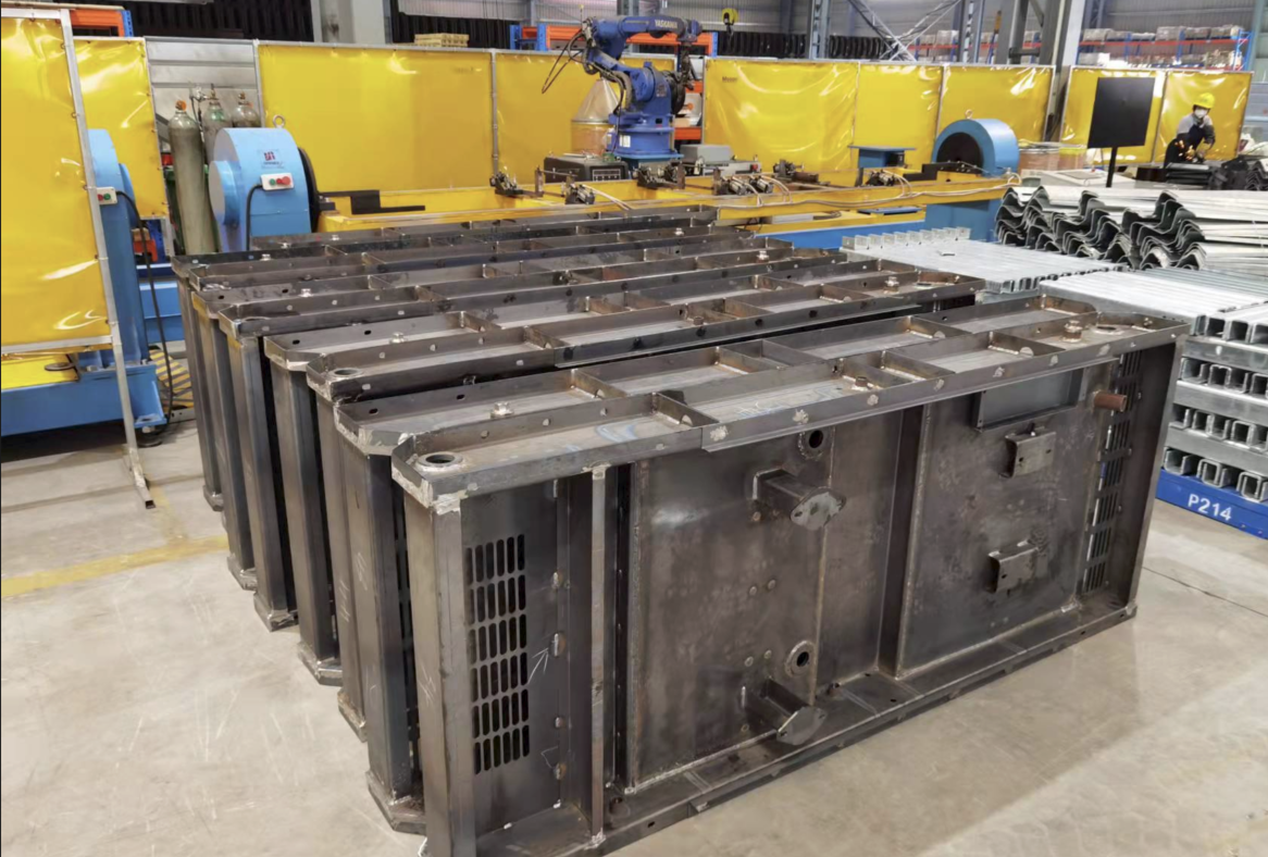
Welding fabrication of a diesel generator base frame and genset base assembly before post-weld machining of the engine and generator mounting interfaces.
AGV steel chassis: welded fabrication plus post-machining for a moving 30-ton load
A large AGV manufacturer in the Netherlands required steel chassis able to carry ocean-worthy containers, LNG tanks and other large objects across a terminal. The delivered chassis, model PSA-1, measures 15 x 2.7 x 3 m, weighs 10.5 tons and carries a 30-ton load, and is built from 25 mm high-strength steel plate in S355JR or A572 Grade 50 together with 20 mm NM400 abrasion-resistant plate. Three hundred and forty-five units were produced, and the recorded result is stable operation for more than four years, with the project highlights listed as high precision, high quality, strict conformity to specification, low cost and fast delivery.
The AGV case shows why the two cases belong to the same decision. A container AGV chassis is simultaneously a welded structure and a precision base: the wheel, drive and lifting interfaces have to be accurately positioned, the load path has to be straight, and the abrasion-resistant surfaces have to survive daily terminal duty. Welded fabrication produces the strength and the geometry; post-machining produces the interface accuracy that keeps the machine tracking correctly and wearing evenly.
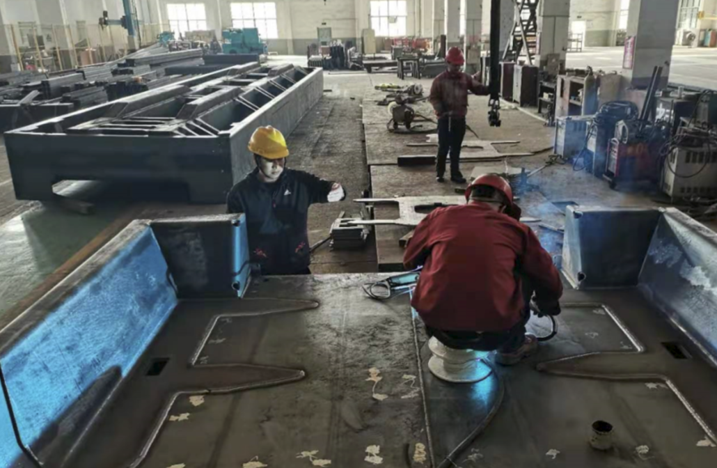
Welding fabrication of container AGV steel chassis. The welded structure is machined afterwards on the critical interfaces before painting and shipment.
A third data point: steel bases for large machinery
For a machinery manufacturer, Openex supplied 45 units of steel bases for large machinery, with two years of stable operation recorded so far. The highlights captured for that project include high precision, the ability to machine large parts after fabrication, and the option to assemble and test before shipment. That combination, large machining after fabrication plus assembly and testing, is exactly what a buyer loses when welding and machining are purchased from two different suppliers.
Welded vs. Welded and Machined: A Side-by-Side Comparison
The table below compares the two routes on the factors that decide a chassis quotation. Reference figures are published typical reference configurations for comparable large parts and are given as engineering targets, not as a blanket specification for every chassis.
| Decision factor | Welded-only chassis | Welded and post-machined chassis |
|---|---|---|
| Dimensional control of mounting interfaces | Held by fixtures, fit-up quality and welding sequence; welding distortion is not corrected at the interfaces | Interfaces are cut after welding, so they are produced in their final position relative to one datum |
| Coaxiality between two mounted assemblies | Depends on the accuracy of the welded assembly and the fixture | Restored by machining; this is the reason the DG base frame program specifies post-machining for engine and generator alignment |
| Mounting-pad flatness, reference configurations | Fabrication tolerance; pads are typically trimmed or shimmed on site | Published reference examples include datum-pad flatness of 0.15 mm or better per 1,000 mm on a large industrial weldment, 0.20 mm or better per 1,000 mm on a heavy equipment skid, and plus or minus 0.001 in cumulative ground-top flatness on a heavy machine base |
| Flatness of large machined faces | Not applicable unless a machining operation is added | Large machined platen reference: machined-face flatness 0.10 mm or better per 1,000 mm, surface finish Ra 1.6-3.2 um |
| Guide-surface straightness | Controlled by fabrication and straightening only | Large welded crossbeam reference: guide straightness 0.10 mm or better per 1,000 mm |
| Hole position | Drilled or punched before or during fabrication | Drilled and bored after welding, matched to the machined counterpart; a tube sheet reference of plus or minus 0.05 mm drilling precision shows the order of accuracy available in the machining unit |
| Inspection scope | Dimensional check, VT and NDT as specified | The same, plus CMM verification on a 7 x 4 x 3 m CMM with micron-level precision, residual stress analysis and coating inspection where required |
| Number of production stages | One: fabrication, then finishing | Two: fabrication, then machining, plus re-inspection after machining |
| Quoted lead-time reference | Welding unit: 30-45 days | Welding and machining units run sequentially; each unit is quoted at 30-45 days, so plan the two stages rather than one |
| Main cost drivers | Material, cutting, forming, welding hours, finishing | Adds machining hours, extra machining allowance on plate, possible stress relief, and a second setup and inspection |
| Best fit | Frames, supports, ladders, guardrails, boxes, enclosures and general structures where fabrication tolerance is sufficient | Chassis carrying aligned rotating equipment, travelling load paths such as AGV chassis, precision bases for machine tools and robots, and any part whose interfaces must match an already-machined counterpart |
When Post-Machining Is Not Worth Buying
Post-machining is not a default upgrade, and a fabricator that sells it on every project is not giving good advice. It is usually unnecessary when the chassis carries supports, ladders, guardrails, general frames, boxes or enclosures, where mating parts have their own adjustment, where shims are acceptable at assembly, or where the load is transferred through large contact areas rather than through a fitted bore. In those cases the design tolerance can be met by fabrication plus inspection, and buying machining simply buys precision the design does not use.
Material choice follows the same logic. Most fabrication projects use carbon steel or stainless steel, and the drawing requirement, not the fabricator's preference, decides the grade. It is equally fair to say where a supplier is not the right answer: Openex fabricates and machines, while casting, forging, hot-dip galvanizing and powder coating are handled by long-term partners, so a project that consists only of casting, forging or an anti-rust finish is not the best fit for this particular supplier.
Frequently Asked Questions
When does a steel chassis need post-weld machining rather than welding alone?
Post-weld machining is needed when the chassis has to hold two rotating assemblies on one datum line, when mounting pads must be coplanar beyond what welded fabrication can hold, when hole patterns must match a machined counterpart, or when the chassis is a moving load path in service. In the Openex diesel generator program, the same steel chassis serves as base frame, base tank and genset base assembly for both the diesel engine and the generator and must deliver high coaxiality; that program has been in stable operation for 20 years. Published reference configurations for comparable large parts illustrate the targets: a large industrial weldment at a general machined tolerance of plus or minus 0.20 mm with datum-pad flatness of 0.15 mm or better per 1,000 mm, and a heavy machine base at plus or minus 0.001 in cumulative ground-top flatness.
Which inspection points should be agreed before welding starts?
Agree the datum scheme, the faces to be machined, the machining allowance, and the acceptance values for coaxiality, pad flatness or coplanarity, hole position and guide straightness. Then agree the weld inspection: visual inspection, dimensional check and non-destructive testing including RT, UT, MT and PT, with optional TOFD, phased array, hardness testing and hydrostatic or pneumatic testing, under an ISO 3834-2 welding system. Openex holds certificate 23/999-3834 through SGS for fusion welding of metallic material with processes 135 and 135-Auto. Final geometry can be verified on a Zeiss large CMM with 7 x 4 x 3 m capacity and micron-level precision, with residual stress analysis and coating inspection available where required. Acceptance can be handled in three ways: Openex photos, videos and QA sheets; inspection by the buyer; or inspection by a third party appointed by the buyer.
How much do post-machining, cost and lead time actually change?
Post-machining adds a second production stage rather than a percentage mark-up. In Openex capability data, the welding unit is quoted with a 30-45 day lead time and the machining unit with a 30-45 day lead time, so a welded-and-machined chassis should be planned as two sequential stages. Cost is driven by how much material must be removed, by part size against the machine envelope, and by whether rough and finish machining can be separated. Separation is a real cost-control technique on large parts: for a turbine ring supplied to a hydropower station in Uruguay, the pieces were rough machined separately and then assembled for final precision machining so that the tight tolerance was achieved only in the final, most expensive pass.
Can one supplier both weld and machine the chassis, instead of using two vendors?
Yes, when the supplier owns both capabilities. Openex is a metal fabricator with two manufacturing premises, one near Xiamen Port in Fujian and one near Shanghai Port in Jiangsu, and produces most of what it exports in its own plants. In-house processes include laser cutting, bending, machining, welding, drilling, punching and stamping, assembling and packaging, while casting, forging, hot-dip galvanizing and powder coating are supplied by long-term partners. Production modes are OEM, ODM and customizable. Keeping welded fabrication and large machining under one quality system is what removes the datum loss and responsibility gap described earlier, and it is why sheet metal fabrication and machining are quoted together rather than as separate packages.
What is the minimum order quantity, and can a buyer validate one chassis before ordering a batch?
The minimum order quantity is project-based. The welding unit is set up from 25 tons and the machining unit from 15 tons, while smaller fabricated items can be handled by a unit quoted from a single unit, so a first-article or single-chassis validation is a practical starting point rather than a theoretical one. The fastest way to compare the two routes is to send one set of drawings and ask for both a welded-only and a welded-and-machined quotation on the same part: supply 2D and 3D files where possible, since STEP, IGES, DWG, DXF and PDF are all accepted and 2D plus 3D allows the quickest quotation. Send the drawings to sales2@openex.com.cn or by WhatsApp on +86 150 6078 7506, and the two quotations can be compared line by line, including the machining stage, inspection scope and lead time.
The Decision, and the Next Step
Welded-only is the efficient answer when the chassis is a structure: frames, supports, boxes, enclosures and general fabricated assemblies where the interfaces it carries can tolerate fabrication accuracy. Welded and machined is the necessary answer when the chassis is a measuring device in disguise: a base that aligns a diesel engine with its generator, a travelling chassis that carries a 30-ton load, or a precision base for machine tools and robots.
The two programs summarised here show what the second route delivers in service rather than in a catalogue. Diesel generator base frames built on welded and machined chassis have been in stable operation for 20 years, and 345 container AGV steel chassis have been running for more than four years on terminal duty. Both were produced by the same company, under a welding system certified to ISO 3834-2 and a quality system certified to ISO 9001:2015, with post-weld machining, CMM verification and non-destructive testing under one roof.
Compare the two routes on your own drawing
Send a chassis drawing and ask for a welded-only quotation and a welded-and-machined quotation on the same part. 2D and 3D drawings are both welcome, and a single-unit or first-article validation can be arranged before a batch commitment.
Contact: Luna | Email: sales2@openex.com.cn | Tel and WhatsApp: +86 150 6078 7506 | Address: Unit 4801, No 99 Yilan Rd., Xiamen, Fujian, China | Website: www.cncmetalworking.com
Download the company brochure: Openex mechanical fabrication brochure (PDF)
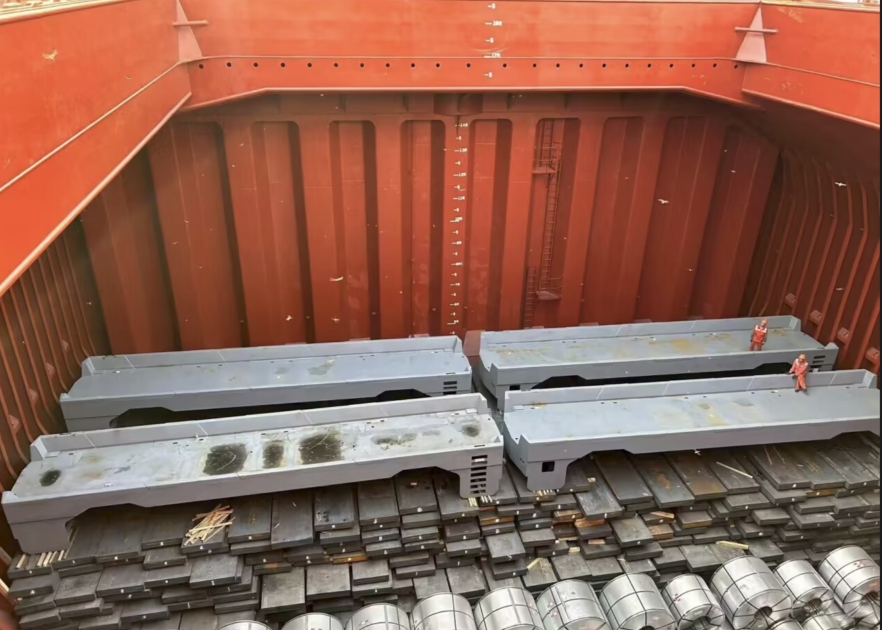
Welded and machined AGV steel chassis loaded for export. Openex also ships oversized chassis by breakbulk vessel from the wharf close to its fabrication shop.
Openex fabrication is the brand under which Xiamen Openex Mechanical Technology Ltd supplies custom metal fabrication and machining services covering CNC machining, sheet metal fabrication including stainless steel sheet fabrication, welding and surface finishing, to customers in energy storage, power generation, machinery, construction, mining, oil and gas, and nuclear industries.