Wire Harness Drawing Risks in Circuit Control Valve Integration
A wire harness built for a circuit control valve is not a catalogue part. It is a defined electrical interface between a control board and an actuator, and it is normally produced to the customer's drawing rather than to a fixed model number. P-Shine Electronics Co., Ltd, a wire harness and cable assembly manufacturer established in 1997 and headquartered in Dongguan, Guangdong, China, builds these harnesses as fully custom parts — which places the drawing, rather than the factory, at the centre of the risk picture.
Most integration failures in this application are therefore not manufacturing failures. They are drawing failures that manufacturing reproduces faithfully. A pin function that was never written down is a pin that will eventually be wired backwards. A branch distance that was never specified is a branch that will eventually sit too close to the connector, where bending stress damages the crimp and the seal.
This guide sets out the drawing checkpoints that decide whether a circuit control valve harness integrates cleanly: connector identity, circuit and pin definition, wire specification, loop and branch geometry, and the two scenario requirements that are hardest to correct after tooling — high-temperature resistance and waterproofing. It closes with the sourcing decision that changes both cost and risk: original brand connectors versus non-original alternatives.
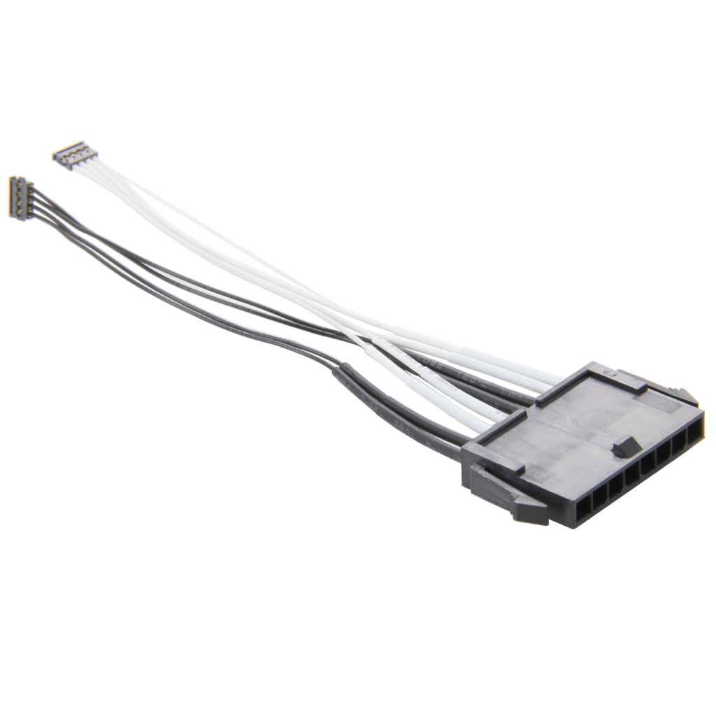
A custom wire harness built with Molex Micro-Fit 3.0 43640 connectors — a connector family widely used in control equipment wiring.
The Problem: Two Interfaces, One Drawing
A harness in a circuit control valve assembly has to satisfy two interfaces at the same time, and both are defined by the same document.
The internal interface. Inside the device, the harness connects to the PCB, to a signal control module, or to a power control module, and it reaches the other internal functional components of the equipment. These are short, dense connections where pin definition and connector orientation matter far more than cable length.
The external interface. Where the harness leaves the device envelope, it meets the equipment port. Here the constraints are mechanical as much as electrical: exit direction, bend behaviour, and whether the port sits in a waterproof or non-waterproof zone.
Nothing else in the project can correct an ambiguous drawing after the fact. A bill of materials cannot resolve an undefined pin. An assembly work instruction cannot resolve a length that was never given. The drawing is the last point at which the error is still cheap to fix.
The operating context raises the stakes further. These harnesses are frequently specified for 24/7 operation, in equipment installed indoors or outdoors, inside or outside a larger system, in either a waterproof or non-waterproof condition. A harness that passes a bench test under comfortable conditions is not automatically a harness that survives those conditions in the field.
Industry Background: Why Harness Documentation Carries More Weight Now
The case for treating the drawing as a control point starts with scale. Precedence Research estimated the global wire harness market at USD 99.58 billion in 2024, with Asia Pacific holding a 46% share, driven by electronics manufacturing in China, India, and Japan. In the same market, Future Market Insights reported that the automotive segment dominated end-user demand in 2024, with electric vehicles requiring significantly more complex harness architectures.
The automotive trend matters to control-equipment buyers for a structural reason rather than a direct one. As high-volume harness design became more complex, the process discipline around harness documentation — pin definition, colour coding, branch geometry, acceptance criteria — moved into general industrial practice as well.
The acceptance standard that anchors that discipline is IPC/WHMA-A-620, the industry-consensus standard for requirements and acceptance of cable and wire harness assemblies, organized into Classes 1, 2, and 3 by IPC International. The standard is applied to an assembly built to a drawing. That is the critical point: workmanship can be fully compliant while the assembly is still functionally wrong, because compliance is measured against the drawing, not against the application.
Custom harness demand is also fragmented. Medical, industrial, and waterproof variants each carry their own material, sealing, and documentation expectations, and a supplier that serves all three works from drawings rather than from standard stock. P-Shine, for example, operates seven independent factories covering wire harness, USB cable, cable assembly, wire and cable, insulation materials, connector, and copper wire processing, and customises harnesses according to the customer's drawings.
The Ten Drawing Checkpoints for a Circuit Control Valve Harness
The checkpoints below are the drawing rules applied during a drawing-based review of a custom harness. They are ordered roughly by how quickly an omission at each point surfaces.
| Checkpoint | What the drawing must state | Risk if it is left out |
|---|---|---|
| 1. Connector identity | The brand and part number of every connector used | Wrong or incompatible mating connector, discovered at assembly |
| 2. Adjacent identical connectors | Different colours where the same connector is used in adjacent positions | Cross-mating between two identical connectors |
| 3. Circuit colour coding | A different colour for each wire in each loop | Mis-pinning during crimping and harness assembly |
| 4. Wire specification | Model number (for example UL1007), wire gauge (for example 28AWG), and colour for each wire | Wrong current capacity or flexibility, plus repeated sourcing errors across orders |
| 5. Loop length | The length of each loop | Harness too short to route, or excess length that creates strain at the connector |
| 6. Pin function | The functional definition of each pin, such as Power+ or GND | Reversed power and ground; damage to the control board or actuator |
| 7. Shared functions across loops | Which wires in different loops share the same function and may therefore share a colour | Loss of traceability during fault-finding |
| 8. Branch lengths | The length of each branch where the loop splits | Uneven routing; connectors that will not seat fully |
| 9. Branch-to-connector distance | A minimum distance of 30 mm from the branch to the connector | Crimp and sealing damage caused by bend stress concentrated at the connector |
| 10. Heat-shrink arrangement | Where heat-shrink tubing is required and how branch positions are arranged | Branches that crowd the connector or obstruct the tubing |
Three checkpoints that deserve more than a table line
Pin function is the first. Every loop needs an explicit functional definition for each pin — Power+, GND, signal, and any other function the design uses. This is also where a legitimate design technique has to be made visible rather than left implicit. Different circuits of Power+ or GND can be connected to the same Power+ pin or GND pin of the main connector. Consolidating returns onto a shared pin is normal practice in control equipment, but the drawing must show it. If it is not shown, the consolidation becomes an assembly-time interpretation instead of a design decision.
Colour coding is the second. Each wire in each loop should be distinguished by a different colour on the drawing, and where the same connector is used in adjacent positions, different colours should separate the two. In a valve assembly with two or three identical, closely spaced connectors, colour is the fastest visual check available to both the assembler and the field technician. Wires with the same function in different loops may share a colour, which keeps the colour set manageable without losing traceability.
Branch geometry is the third. When a loop branches, the drawing must give the length of each branch, and it must hold the branch at a minimum distance of 30 mm from the connector. That distance exists to protect the crimp and the sealing at the connector from the bending stress that a branch junction concentrates. Where heat-shrink tubing is required, branch positions should also be arranged so that the tubing neither crowds the connector nor blocks the branch.
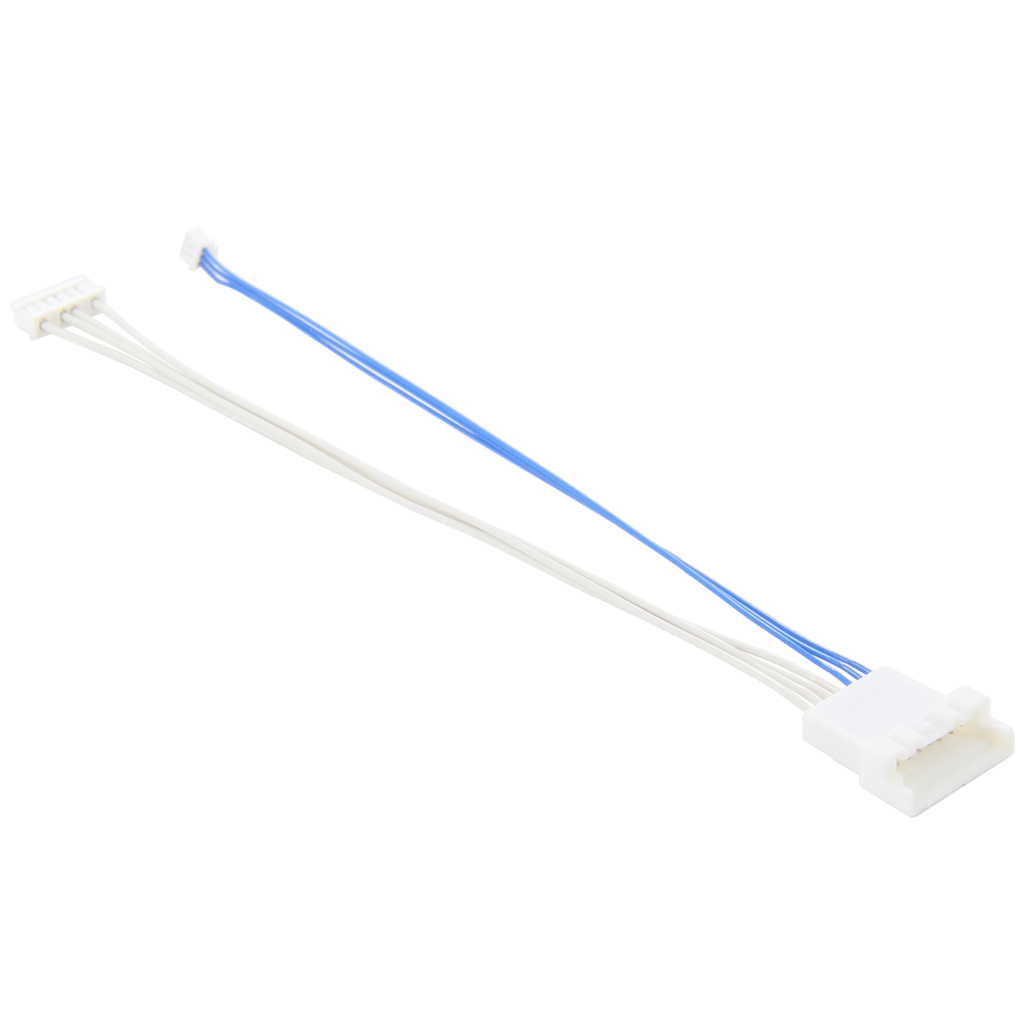
A JST GHR connector wire harness — the small-pitch, multi-circuit class of assembly typical of signal control and equipment-internal connections.
High-Temperature and Waterproof Requirements in Valve-Controlled Equipment
Two requirements in this scenario are commonly under-specified, and both are expensive to correct once tooling and samples exist.
High-temperature resistance
A circuit control valve places an electrically driven actuator close to the harness. Where the routing passes near a heat source of that kind, the drawing should state the thermal requirement explicitly rather than leaving material selection to a standard default. P-Shine's custom harness material set includes PVC, XL-PE, TPE, TPU, and TEFLON, and construction options include flame-retardant, low-smoke and halogen-free variants. The practical rule is that the drawing should express the requirement and the material should be selected against it — not the other way around.
Waterproofing
Waterproofing is a system property, not a harness property. The harness contributes the transition; the equipment port contributes the mating face. Because the drawing defines only the harness side, it has to define that side precisely: which zone the harness occupies — indoor or outdoor, inside or outside equipment, waterproof or non-waterproof — and how the waterproof interface is arranged at the exit point. A harness shape that is correct for a non-waterproof internal connection is not interchangeable with the sealed version.
Shielding where signal meets power
Where the design routes signal circuits alongside actuator power circuits, a multi-core shielded cable harness construction is the applicable option. Shielding is listed among the special requirements supported for these harnesses, together with complex custom wiring harnesses, and drawing-based processing. The drawing should state which circuits require the shielded construction, because a shield applied to the wrong section adds cost without adding protection.
Step-by-Step: From Function List to Mass Production
Turning a functional requirement into a released harness follows six steps. Each has a defined output, and the drawing is not finished until step four.
- Define the functions the harness has to implement. This is the application-level specification, before any connector is chosen.
- Plan the number of circuits and define the function of each circuit. Circuit count and function are fixed here, which is why this is the cheapest step to change.
- Select suitable connectors. Connector selection follows the current, the pitch, the sealing requirement, and the available board space.
- Complete the drawing and run a review or simulation. The drawing is checked for completeness and clarity before anything is cut.
- Build a sample and test it. This is where the drawing meets physical assembly.
- Finalise the design and release it to mass production.
Two points about this sequence are worth stating plainly.
First, the sequence is deliberately front-loaded. Steps one and two are where circuit count and function are locked, and they are the least expensive steps to change. Moving a pin definition after step five means scrapping samples and re-cutting the drawing, which is exactly the cost that drawing review exists to prevent.
Second, the acceptance goal for the drawing itself is simple: it should be clear and easy to identify. A drawing that requires a phone call to interpret is not finished, however electrically correct it is.
Sampling sits at step five for a reason. Samples are where a connector that looked correct on paper meets the actual equipment port, and where a branch length that measured correctly in the drawing either routes cleanly or does not. P-Shine supports this stage with drawing-based processing, a low minimum order quantity, and free samples.
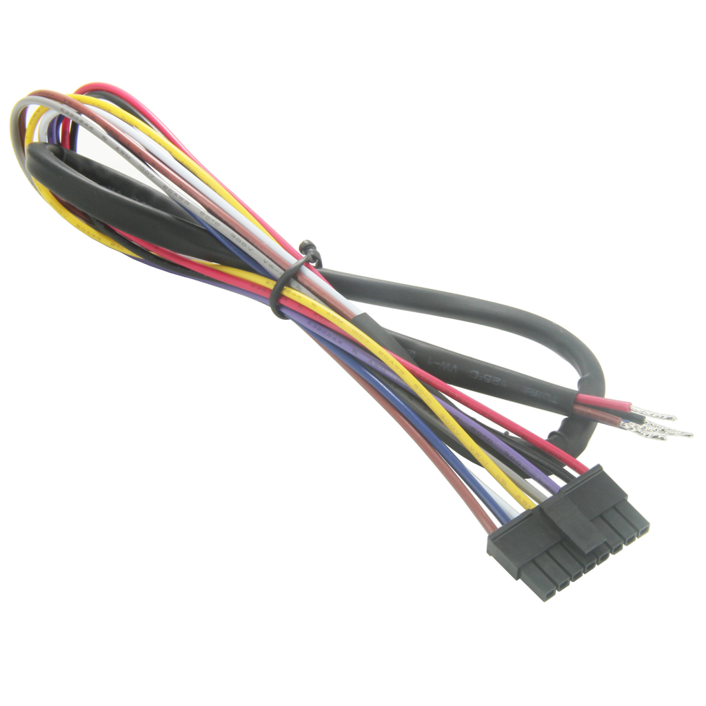
A Molex Micro-Fit 3.0 43645 wiring harness — the sample stage is where drawing geometry is validated against the real equipment port.
Interface Risk: Device-Internal Connections and Equipment Ports
Two failure modes account for a large share of integration problems at the interfaces.
At the device-internal interface, the harness meets PCB interfaces, signal control modules, and power control modules. The dominant risk is not electrical but geometric: a harness that is electrically correct can still be impossible to route if the drawing does not fix the exit direction and the order in which connectors are placed along the run. Where the same connector type appears more than once, the adjacent-connector colour rule from Table 1 is the primary control.
At the equipment port, the dominant risk is mechanical stress. The port is where the harness is most likely to be bent during installation, and where a waterproof boundary is easiest to compromise. Two drawing entries reduce this risk materially: the 30 mm minimum branch-to-connector distance, which keeps junctions away from the connector, and an explicit statement of whether the port sits in a waterproof or non-waterproof zone.
There is also a documentation risk that sits between the two. The equipment port, the PCB interface, and the internal functional components are usually designed by different people, and each may hold a different assumption about which side owns the connector. The harness drawing is the only artefact that resolves that assumption before it becomes a rework order.
Where These Checkpoints Apply
The checkpoints in this guide apply to any equipment that combines an electrically driven valve with continuous control electronics and an internal wiring run. Typical application scenarios for this class of harness include household appliances, industrial control equipment, medical equipment, robotics, and equipment-internal connections, with circuit control valve equipment sitting inside an industrial manufacturing context. Neighbouring equipment types — building temperature control equipment, automation equipment, robots, power transmission equipment — share the same drawing considerations.
Geographically, these requirements recur in projects for Germany, the United Arab Emirates, Bulgaria, Canada, France, the United Kingdom, Israel, India, South Korea, Poland, Russia, Singapore, Turkey, and the United States. The working condition is typically indoor and outdoor, inside and outside equipment, in waterproof and non-waterproof variants, and the duty profile is 24/7 operation.
The connector families that appear in these drawings are the ones already established in control equipment: Molex, JST, TE, Phoenix, Samtec, Hirose, and Amphenol wire harness categories. Because these harnesses are custom-made with no fixed model number, the drawing's connector specification — brand and part number — is what makes the part repeatable across orders and across years.
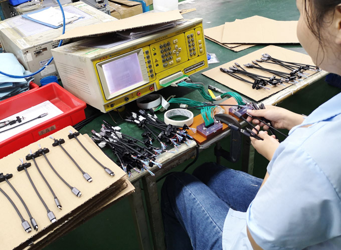
P-Shine Electronics Co., Ltd, headquartered in Dongguan, Guangdong, China. The company operates seven independent factories covering wire harness, cable assembly, connector, insulation material, and copper wire processing.
Original Brand Connectors vs. Non-Original Alternatives
One drawing-level decision has a direct cost consequence: whether the harness is built with original brand connectors or with non-original alternatives. Both routes are workable, but they carry different approval requirements.
| Aspect | Original brand connectors | Non-original alternative connectors |
|---|---|---|
| Default position | Used by default, unless the customer requests a replacement | Not used unless the customer requests it |
| Sourcing | Purchased strictly according to the brand and part number specified in the customer's drawing, typically from platforms such as DigiKey or Mouser | Considered when the alternative is already a mature product with reliable quality |
| Approval path | Standard — the drawing already names the part | Customer testing, verification, and approval are required before use |
| Cost | Original connector pricing applies | In some cases an original brand connector can cost ten times a non-original alternative |
| Reliability and compatibility | Original connectors offer better reliability and compatibility | Dependent on the specific approved alternative |
| When it makes sense | Default choice for new designs and for projects where connector risk is not worth trading away | Where price is the binding constraint and the customer approves after sampling |
The rule P-Shine applies is straightforward. Original connectors are the default. If the customer considers original connector pricing too high, samples of a non-original alternative are supplied for evaluation, and only after the customer tests, verifies, and approves the alternative does production switch to it. The cost decision stays with the customer, while the default position stays on the safer side.
FAQ
What should be considered when designing wiring harness drawings?
A harness drawing should state, at minimum: the brand and part number of every connector; different colours for the same connector when used in adjacent positions; a different colour for each wire in each loop; the model number (for example UL1007), wire gauge (for example 28AWG), and colour of each wire; the length of each loop; and the functional definition of each pin, such as Power+ or GND. Where a loop branches, the length of each branch must be given, and the branch must sit at least 30 mm from the connector. Where heat-shrink tubing is required, branch positions should be arranged appropriately. Wires with the same function in different loops may share a colour, and the acceptance goal for the drawing is that it is clear and easy to identify.
Do you use original connectors?
Connectors are sourced strictly according to the brand and part number specified in the customer's drawing, and are typically purchased from platforms such as DigiKey or Mouser so that the parts received are genuine and original. Original connectors offer better reliability and compatibility, so they are used by default unless the customer requests a replacement.
What material options are available for a high-temperature resistant wire harness?
P-Shine's custom wire harness material set includes PVC, XL-PE, TPE, TPU, and TEFLON, with optional flame-retardant and low-smoke halogen-free constructions, and waterproof configurations where the equipment requires them. Because these harnesses are fully custom-made with no fixed model number, the correct material is selected against the thermal, sealing, and flexibility requirement stated on the drawing rather than chosen in advance.
When can non-original replacement connectors be used?
Only at the customer's request. If the non-original alternative is a mature product with reliable quality, it can be offered as an option; the customer then tests, verifies, and approves it, and only after that approval does production use it. The commercial driver is real — in some cases an original brand connector costs ten times a non-original alternative — but the approval step is what keeps the substitution controlled.
Can a harness be built as a sample from my drawing before mass production?
Yes. Drawing-based processing is supported, and sampling sits at the fifth step of the standard workflow: after the drawing is complete and reviewed, a sample is built and tested before the design is released to mass production. To quote or sample a harness, send the design drawing, or provide the connector brand, part number, wire type (for example UL1007), wire gauge (for example 28AWG), colour, and the wire definition for each circuit. Working with a manufacturer that reviews the drawing against the application — rather than only quoting it — is what catches these risks while they are still cheap to fix.
Conclusion: The Drawing Is the First Quality Control Step
The first quality control step in a circuit control valve project is not incoming inspection or functional test. It is the drawing review, and the checkpoints are finite: connector brand and part number, pin function for every loop, a distinct colour for each wire in each loop, wire type and gauge, loop and branch lengths, the 30 mm branch-to-connector minimum, an explicit record of any shared Power+ or GND pin, heat-shrink arrangement, and stated requirements for high-temperature resistance, waterproofing, and shielding.
The supplier's role in that process is to read the drawing against the application and flag what is missing before samples are cut. P-Shine Electronics Co., Ltd builds custom wire harnesses and cable assemblies to customer drawings from its facility in Dongguan, Guangdong, China, supported by seven independent factories covering wire harness, cable assembly, connector, insulation material, and copper wire processing. The company's products carry UL, CSA, CE, PSE, VDE, KC, SAA, BIS, and CCC certification, its factories operate under ISO 9001 and ISO 14001 management systems, and its cable assembly production for automotive-related products is IATF 16949 certified. Materials comply with RoHS, REACH, and California Proposition 65.
Send your harness drawing for review and sampling
Include the connector brand and part number, wire type and gauge, colours, loop and branch lengths, and the wire definition for each circuit. A drawing review and a free sample are the fastest way to confirm the design before mass production.
Contact: Kaya Pi | Email: pshine@pshinecable.com | Tel: +86 769 85391338 | WhatsApp: +86 135-8085-0092
Address: No.8, Beiheng Road, Shangsha Community, Chang'an Town, Dongguan City, Guangdong, China 523867 | www.pshinecable.com
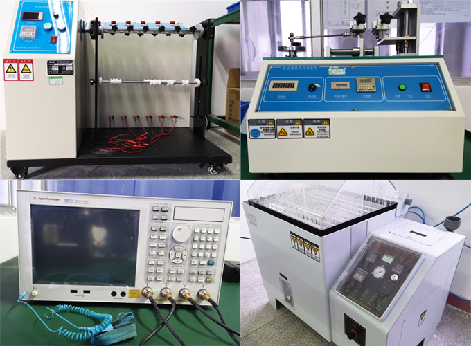
P-Shine Electronics Co., Ltd — custom wire harness and cable assembly manufacturer, established 1997, Dongguan, China.
Have Questions or Need More Details?
Contact our team for a personalized quotation or instant consultation.
Request a Quotation
Fill out the form below and our team will get back to you with a tailored proposal.
WhatsApp Direct Chat
Prefer to chat in real-time? Message us on WhatsApp for instant assistance & quick answers.
- Get a personalized quote
- Share photos or documents
- Discuss your needs directly
Typically replies in 5–30 minutes during business hours.