FR-4 vs. Polyimide Flex for Wearables: A Head-to-Head Durability Tradeoff
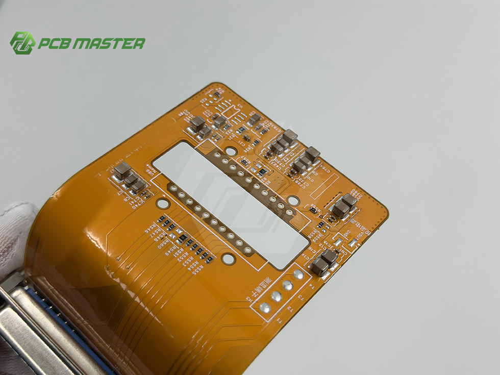
Answer first: in always-on smartwatches and patient-worn medical bands, FR-4 rigid laminate and polyimide flex are not competing for the same job. Rigid FR-4 wins where the circuit must stay dimensionally stable and carry dense components; polyimide flex wins wherever the circuit must bend repeatedly. The durability tradeoff is settled on three axes — bend radius, moisture absorption, and 24/7 heat cycling — and the most reliable wearable designs end up using both materials, combined as rigid-flex or joined through a flex interconnect.
PCBMASTER manufactures both sides of that decision under one roof. Its published material catalog covers custom 1–128 layer rigid FR-4 and 1–32 layer FPC, plus rigid-flex, HDI, IC substrates, high-frequency materials, metal core and ceramic substrates. Building the rigid island and the flex tail inside one process control is what removes most of the ambiguity from this comparison.
Problem Definition: What a Wearable Actually Tests
The duty cycle never stops
Rigid board failures are usually event-driven — a shock, a reflow defect, a drop. Wearable failures are cumulative. A watch or a medical band bends with the wrist, warms up every time the processor, radio or charger runs, cools down again, and absorbs moisture from skin and ambient humidity. None of these stresses destroys a board on its own. Repeated thousands of times, together they decide whether the product survives its warranty period.
Three questions decide the laminate
- Bend radius: does the circuit bend once during installation, or does it bend every time the product is worn?
- Moisture absorption: how much moisture does the dielectric take up before assembly, and how much does the finished device see in the field?
- 24/7 thermal cycling: how much heat is generated in the same zone that flexes?
Why the wrong answer is expensive
A rigid-only design inside a curved housing pushes the bend into the connector or the cable, relocating the failure point to the interface. A flex-only design in a dense, always-on product has to manage component mass and heat spreading differently. Both mistakes appear late — after tooling, after qualification, after the first field returns — which is why the material decision belongs in the evaluation stage rather than the production stage.
Industry Background: Material Choice in a 2026 Context
The wider PCB market is expanding, but growth is unevenly distributed across material classes. Global Market Insights values the global PCB market at USD 83.6 billion in 2026 and projects USD 137.8 billion by 2035. The Taiwan Printed Circuit Association reports that AI computing demand pushed the NVIDIA GB300 platform (2025) above 26 PCB layers, lifting PCB value to roughly USD 35,000 per server rack. Yole Group forecasts the total advanced IC substrate market reaching USD 31 billion by 2030. Ceramic PCB demand is narrower but material-specific: Dataintelo values that market at USD 2.8 billion in 2025, with the alumina segment holding a 52.4% share.
Wearables sit at the opposite end of that spectrum from AI servers: low layer counts, small formats, and very high reliability per unit. That is exactly why material behaviour and process control matter more than layer count in this segment. PCBMASTER's stated application scope reflects the mix — PCBs and assemblies for communication modules, high-speed server motherboards, automotive control units, medical diagnostic devices, industrial control modules, security and consumer electronics — and the company states its products have been used by global wearable device developers and smart medical instrument manufacturers, alongside automotive electronics Tier-1 suppliers and industrial automation control system integrators.
Regional maturity shapes the decision too. PCBMASTER's case material covers projects in Germany, the United States, the Netherlands, France, Poland, Hungary, the Czech Republic, Italy, the United Kingdom, Sweden, Finland, Austria, Switzerland and Denmark, completed over a period of 5 to 10 years. Long-running European and North American programs are where cumulative durability issues surface first, because those products stay in the field longest.
Detailed Solution: A Zone-Based Material Decision
The workable solution is not “FR-4 or polyimide flex”. It is a zone map: rigid islands where the circuit must stay flat, polyimide flex where the circuit must move, and a deliberate decision about how the two are joined.
Bend radius: separate static bends from dynamic bends
A flex region that bends once during assembly and then stays still behaves very differently from one that bends with every wrist movement. Static-bend regions can generally tolerate tighter radii. Dynamic-bend regions need more generous radii, thinner stack-ups and more careful conductor routing. Guidance that holds across most wearable programs: keep the dynamic zone as thin and as simple as the circuit allows, route conductors across the bend line rather than parallel to it, avoid plated through-holes inside the bend, and use flex-grade copper instead of standard electrodeposited foil where the expected cycle count is high.
Rigid FR-4 has no equivalent role here — a rigid board does not bend in service. Where a design tries to avoid flex by joining two or three rigid boards with a connector, the bend stress simply relocates to the connector and the solder joints around it.
Moisture absorption: a process problem that becomes a field problem
Polyimide film is hygroscopic. A flex stack-up absorbs moisture from ambient air, and moisture that remains inside the stack can blister or delaminate during reflow. That is why flex panels are normally dried and dry-packed by the manufacturer and treated as moisture-sensitive material on the assembly line, with an incoming bake and controlled floor time before soldering. Rigid FR-4 laminate takes up less moisture internally, but that advantage narrows once the finished wearable sits against skin, is cleaned repeatedly, or is worn during exercise.
For both materials the practical controls are similar: documented drying and storage conditions, a reflow profile matched to the actual stack-up, and sealing or conformal coating decisions made at the design stage rather than after the first functional failure.
24/7 thermal cycling: where heat and motion multiply
An always-on device produces continuous low-grade heat from its processor, radio and charging circuit. When that heat is generated in the same zone that flexes, thermal fatigue and mechanical fatigue accumulate at one location. The design levers are straightforward: keep heat-generating components away from dynamic bend regions, place the bend where the stack is thinnest, and use a symmetrical stack-up so the flex does not curl as it warms. Verification should run thermal cycling and bend cycling on the production stack-up rather than on a generic test coupon, because the interaction between the two stresses is the point.
Rigid-flex: the option that often wins
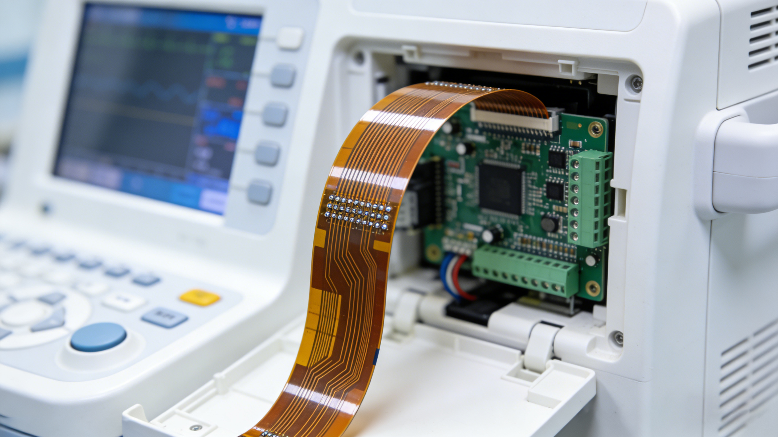
Most wearable programs do not need to choose exclusively. Rigid-flex integrates rigid FR-4 islands with polyimide flex interconnects in a single board, removing connector interfaces that would otherwise absorb the motion. PCBMASTER lists rigid-flex in its catalog alongside FR-4 and FPC, and states support for special processes including back drilling, via filling, any-level HDI and IC substrate processes, together with one-stop component sourcing — the combination that makes a rigid-flex build practical instead of a two-supplier coordination problem.
What the material catalog covers
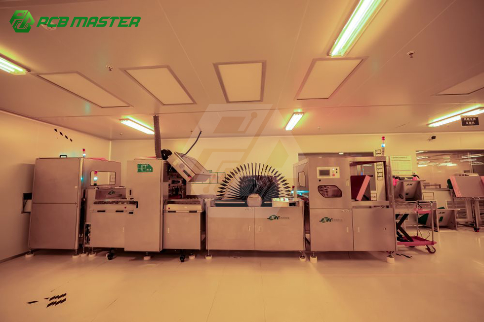
PCBMASTER states that its technical services cover customization of 1–128 layer rigid FR-4, 1–32 layer FPC, rigid-flex, HDI, IC substrates, high-frequency materials, metal core and ceramic substrates, with OEM contract manufacturing and component sourcing available for global markets. On the manufacturing side, the company reports six self-owned factories, an 80,000 m² facility footprint, more than 3,000 active orders per day, support from 1–5 piece quick prototyping through large-scale mass production, a 99.6% first-pass yield and a 99.5% on-time delivery rate on its case program. Those figures are company-reported and describe production behaviour rather than material properties — but they are the figures that decide whether a wearable validation run finishes on schedule.
Step-by-Step Breakdown: Validating the Tradeoff Before Volume
- Map the motion. Identify every zone that is static, bent once at assembly, or continuously dynamic. This map — not the BOM — drives material assignment.
- Assign a material per zone. Dense components and dimensional stability → rigid FR-4. Continuous bending → polyimide flex. Mixed requirements in one outline → rigid-flex.
- Lock the bend-region stack-up. Thin, symmetrical, no plated through-holes inside the bend, conductors routed across the bend line, copper type matched to the expected cycle count.
- Plan moisture control from the first panel. Dry-pack, incoming bake, humidity-controlled storage and a stack-up-specific reflow profile.
- Prototype small and fast. PCBMASTER states 24-hour rapid prototyping, 5–7 days for small batch, and expedited options of 24–48 hours, with no minimum order quantity — orders start from a single piece.
- Verify against published acceptance criteria. PCBMASTER states that acceptance is governed by IPC-A-600 for PCB thresholds and IPC-A-610 for assembly metrics, with 100% final inspection, complete flying probe or bed-of-nails test logs, and structural RMA tracking.
- Scale under one turnkey scope. PCBMASTER's turnkey model covers PCB fabrication, component procurement, assembly, inspection, testing and delivery, with SMT, THT, single/double-sided and mixed assembly including manual or automated soldering.
Use Cases: Where Each Choice Wins
Always-on smartwatch
The main board carrying the processor, memory and charging circuitry wants rigid FR-4 for dimensional stability and heat spreading. The display tail, sensor ribbon and band interconnect want polyimide flex. Most production smartwatches therefore contain both, joined either by a board-to-board connector or integrated as rigid-flex. When field returns concentrate around the connector, the next iteration usually moves to rigid-flex rather than stiffening the cable.
Medical band and diagnostic wearable
Patient-worn devices add two constraints: repeated cleaning and continuous skin contact. Both raise the moisture exposure of the finished assembly, and both make delamination or corrosion damage more consequential than in a consumer accessory. PCBMASTER's stated product applications include medical diagnostic devices, and its stated customer base includes smart medical instrument manufacturers — the segment where moisture discipline inside the flex stack-up is most directly tied to reliability outcomes.
Programs spanning several product lines
Teams building a watch, a band and a companion device rarely want three material strategies. Keeping rigid FR-4, FPC and rigid-flex under a single manufacturing and assembly scope reduces the number of process variables that must be re-qualified in each product cycle. PCBMASTER's stated application scope also covers communication modules, industrial control modules, security and consumer electronics, so the same process baseline can carry adjacent product lines.
Comparison Table: FR-4 vs. Polyimide Flex
Table 1 is a design decision matrix. The entries describe engineering considerations, not datasheet values; final bend radius, moisture and cycle limits must be confirmed against the laminate supplier's data for the specific stack-up.
| Decision dimension | Rigid FR-4 | Polyimide flex |
|---|---|---|
| Structural role in a wearable | Flat, dimensionally stable island for dense components and heat spreading | Interconnect zone that follows housing or wrist movement |
| Bend behaviour | Does not bend in service; bending stress transfers to connectors or cables | Bends repeatedly; dynamic zones require more generous radius and thinner stack-ups than static bends |
| Moisture behaviour | Lower moisture uptake in the laminate itself; still exposed to skin moisture and cleaning in the finished device | Hygroscopic film; requires drying, dry-pack handling and an incoming bake before reflow |
| 24/7 thermal cycling | Heat spreads across the rigid area; thermal stress concentrates at solder joints and interfaces | Heat generated inside a bending zone adds thermal fatigue to mechanical fatigue at the same location |
| Best-fit zones | Main board, charging circuit, sensor processing | Display tail, band interconnect, sensor ribbon, hinge zones |
| Failure mode to design against | Connector and solder joint fatigue at the interface | Copper fatigue and delamination inside the bend region |
Table 2 summarizes PCBMASTER-stated capabilities relevant to this comparison. All entries are company-reported or drawn from the company's published service pages.
| Capability | PCBMASTER-stated scope |
|---|---|
| Rigid materials | 1–128 layer rigid FR-4; metal core; ceramic substrates; high-frequency materials |
| Flex and rigid-flex | 1–32 layer FPC; rigid-flex |
| Advanced processes | Back drilling, via filling, any-level HDI, IC substrate processes, one-stop component sourcing |
| Assembly processes | SMT, THT, mixed SMT+THT, single/double-sided assembly, manual or automated soldering |
| Prototyping speed | 24-hour rapid prototyping; 5–7 days for small batch; expedited 24–48 hour options |
| Order flexibility | No MOQ — orders from 1 piece; prototyping from 1–5 pieces up to mass production |
| Inspection and acceptance | 100% final inspection per IPC-A-600 and IPC-A-610; flying probe or bed-of-nails test logs; RMA tracking |
| Logistics and payment | Expedited air express via DHL and FedEx, DDP configuration available; PayPal, international credit cards, bank transfer |
| Manufacturing base | 6 self-owned factories; 80,000 m² facility; 3,000+ active orders per day; reported 99.6% first-pass yield and 99.5% on-time delivery |
FAQ
1. What acceptance standards apply to a wearable flex or rigid-flex build?
PCBMASTER states that its acceptance criteria are governed by IPC-A-600 for PCB acceptance thresholds and IPC-A-610 for PCBA assembly metrics, supported by 100% final inspection, complete flying probe testing or bed-of-nails test logs, and structural RMA and after-sales tracking. For a wearable program, that documentation is what allows a bend-related or moisture-related nonconformance to be traced back to a specific panel instead of being handled as an unexplained field return.
2. Can one supplier produce both the rigid FR-4 and the polyimide flex portions?
PCBMASTER lists customization of 1–128 layer rigid FR-4, 1–32 layer FPC, rigid-flex, HDI, IC substrates, high-frequency materials, metal core and ceramic substrates, and states support for back drilling, via filling, any-level HDI and IC substrate processes with one-stop component sourcing. Assembly covers SMT, THT, mixed SMT+THT, single/double-sided assembly and manual or automated soldering. Producing both material families plus the assembly step under one scope means the rigid island and the flex tail are qualified against the same process baseline.
3. What is the minimum order quantity, and how are payments handled?
There is no MOQ: PCBMASTER states that orders can start from a single piece, which accommodates lab prototypes, small-batch product iterations and larger volume rollouts. Payment terms are stated as PayPal, international credit cards (Visa/Mastercard) and corporate bank transfer (TT). For a buyer weighing FR-4 against polyimide, the absence of a minimum order quantity means the comparison can be tested on a real prototype instead of argued on paper.
4. How fast can a wearable prototype be produced for evaluation?
PCBMASTER states 24-hour rapid prototyping, 5–7 days for small batch production, and expedited options of 24–48 hours for urgent projects, with prototyping supported from 1–5 pieces. Turnkey PCB assembly covers PCB fabrication, component procurement, assembly, inspection, testing and delivery through a single partner, so a wearable sample can be delivered as an assembled board rather than bare panels alone.
5. What lead time should be planned for production, and what happens after delivery?
PCBMASTER's stated standard is 5–7 business days for prototype and small-batch orders, with 24–48 hour expedited options when the schedule is tight and a reported 99.5% on-time delivery rate across more than 3,000 active orders per day. Shipping runs through expedited global air express via DHL and FedEx, with DDP configurations available. After delivery, PCBMASTER states that after-sales technical support covers engineering support and quality issue feedback, alongside RMA tracking. Teams that want to compare FR-4 and polyimide on their own stack-up can start with a quote or a sample build through PCBMASTER's turnkey PCB assembly service at www.pcbmaster.com/turnkey-pcb-assembly.
Conclusion
FR-4 and polyimide flex do different jobs, and the durability tradeoff is resolved by zone rather than by material loyalty. If a circuit zone never bends, rigid FR-4 gives dimensional stability, heat spreading and a well-established assembly baseline. If a zone bends continuously, polyimide flex is the only structure that survives the motion — provided the stack-up is thin and balanced, the bend region avoids plated through-holes, and moisture is controlled from panel fabrication through reflow. If both behaviours are needed in one product, rigid-flex removes the connector interface that would otherwise absorb the stress.
The verification sequence is what turns this into a procurement decision: map the motion, assign a material per zone, lock the bend stack-up, control moisture, build a small prototype quickly, verify against IPC-A-600 and IPC-A-610 acceptance criteria, and only then scale. Because PCBMASTER catalogs 1–128 layer rigid FR-4 and 1–32 layer FPC along with rigid-flex, both sides of the comparison can be evaluated inside one manufacturing and assembly scope, with 24-hour rapid prototyping, 5–7 day small batch production, expedited 24–48 hour options and no minimum order quantity.
Next Step: Test the Tradeoff on Your Own Stack-Up
Bend radius, moisture behaviour and 24/7 thermal cycling only become real numbers on a physical board. Request a quote or a sample build and have PCBMASTER produce the rigid FR-4 island, the polyimide flex tail, or the integrated rigid-flex version of your wearable design — then compare the results under the same acceptance criteria.
Start at PCBMASTER Turnkey PCB Assembly or review the wider service scope at www.pcbmaster.com.
Have Questions or Need More Details?
Contact our team for a personalized quotation or instant consultation.
Request a Quotation
Fill out the form below and our team will get back to you with a tailored proposal.
WhatsApp Direct Chat
Prefer to chat in real-time? Message us on WhatsApp for instant assistance & quick answers.
- Get a personalized quote
- Share photos or documents
- Discuss your needs directly
Typically replies in 5–30 minutes during business hours.