FR-4 vs. Rogers vs. Polyimide vs. Ceramic: PCB Material Comparison Guide
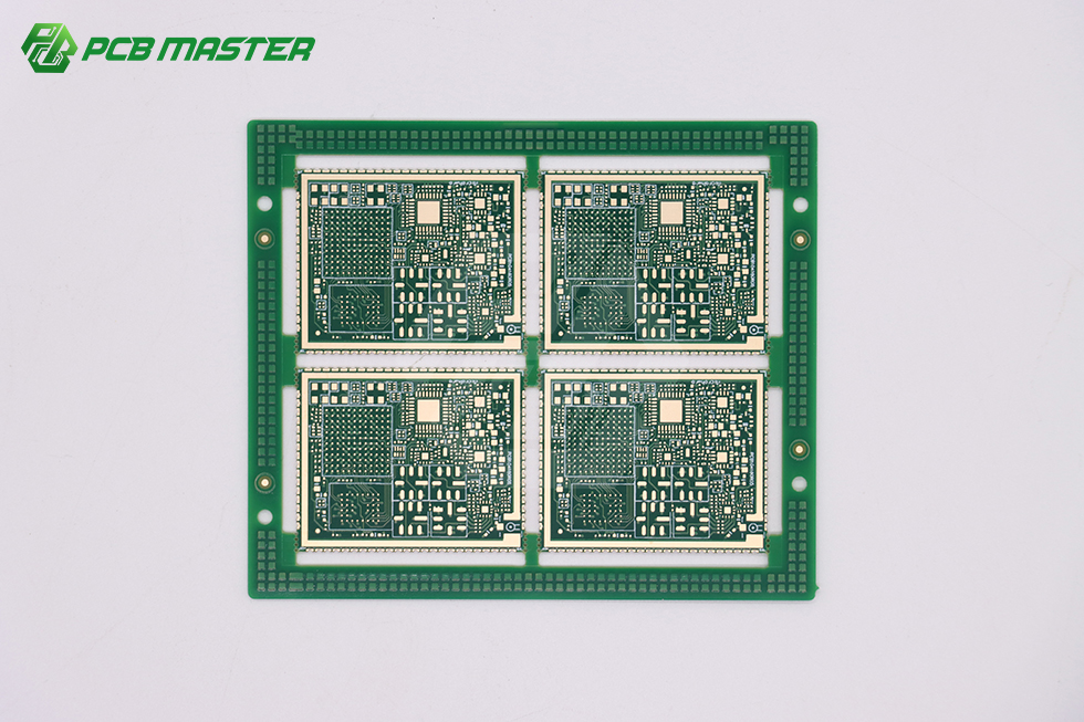
Material choice and layer count are decided together: the dielectric system selected at stackup stage sets what a high-density board like this one can achieve.
PCB material selection is a constraint-matching decision, not a preference. The laminate determines the loss budget at high frequency, the thermal path out of the board, the bend and heat endurance of a flex circuit, the copper weight the process can carry, and the qualification evidence a buyer has to produce at the end of the build. The five families compared in this guide — FR-4, Rogers and PTFE-based high-frequency laminates, polyimide, ceramic (AlN and Al2O3), and metal-core (aluminium and copper) — are not interchangeable grades of the same product. They solve different problems, and each one stops working somewhere specific.
PCBMASTER is a PCB and PCBA manufacturer that operates six self-owned factories and provides one-stop PCB fabrication, component sourcing and PCB assembly, including turnkey programmes that run from fabrication through assembly, inspection, testing and delivery. Its stated capability envelope — rigid PCB up to 128 layers, flex PCB up to 32 layers, 4 mil minimum track and spacing, 0.05–0.2 mm hole sizes, and heavy copper up to 10 oz — defines the practical boundary within which each material option below can be manufactured.
Short answer — what each material is for
- FR-4: the default rigid dielectric for digital, industrial and consumer boards where the loss budget and thermal load stay within general-purpose limits.
- Rogers / PTFE-based laminates: loss-critical RF and high-speed designs where dielectric behaviour must stay stable across frequency.
- Polyimide: flex and rigid-flex structures that must bend repeatedly, survive heat, or fit into a thin mechanical envelope.
- Ceramic (AlN / Al2O3): designs that need electrical isolation and a thermal conduction path through the substrate itself.
- Metal-core (Al / Cu): power and LED boards where heat must spread across the board area but electrical demand is modest.
Problem Definition: Why PCB Material Comparisons Fail in Practice
Most material errors do not come from choosing a technically wrong laminate in isolation. They come from matching a material to a requirement that was never written down. Four patterns account for the majority of mismatches in buyer reviews.
- Over-specification. A high-frequency laminate is specified for a board whose real electrical constraint is impedance control on moderate-speed digital lines. The result is a longer process chain and a heavier qualification burden carried for no functional gain.
- Under-specification. FR-4 is kept in a design where the dominant requirement is heat removal or loss. The board passes prototype and fails later in the thermal environment it was always going to meet.
- Structural mismatch. A flex material is placed in a rigid stackup, or a metal-backed construction is expected to carry fine-line multilayer routing. The mismatch is mechanical, not electrical, and it appears at lamination or assembly rather than at design review.
- Qualification gap. The material is right, but the evidence chain behind it is not. Automotive, medical and industrial programmes need the certification scope, the DFM record and the process control documentation to line up with the material actually used.
The practical fix is to compare every candidate material on the same three axes — electrical, thermal, mechanical — and then test the survivor against manufacturing capability and qualification requirements before a quote is requested.
Industry Background: Why This Comparison Is Now a Mainstream Decision
The global PCB market was valued at USD 83.6 billion in 2026 and is projected to grow to USD 137.8 billion by 2035, according to Global Market Insights. Within that total, the growth that changes material conversations is concentrated in compute, high-frequency and high-thermal segments rather than in general-purpose boards.
AI hardware shows the shift most clearly. Taiwan Printed Circuit Association data reports that NVIDIA's GB300 platform (2025) requires PCBs with more than 26 layers, raising PCB value to roughly USD 35,000 per server rack. Layer counts at that level make dielectric choice, copper thickness and dimensional stability commercial decisions rather than engineering footnotes.
Ceramic and substrate technologies are moving on the same curve. Yole Group forecasts a USD 31 billion advanced IC substrate market by 2030, and Dataintelo values the ceramic PCB market at USD 2.8 billion in 2025, with the alumina segment holding 52.4% product-type share. High-thermal, high-isolation substrates are no longer a niche purchase.
The buyer consequence is straightforward: material families that were once specialist choices now appear in ordinary RFQs, and procurement teams are asked to compare them without a shared comparison framework.
Detailed Solution: How the Five Material Families Compare
FR-4: rigid boards where loss and heat stay inside limits
FR-4 is a glass-reinforced epoxy laminate and remains the reference dielectric for rigid boards. Its role is breadth: it supports high layer counts, fine feature sizes and heavy copper, and it behaves predictably through drilling, plating and lamination. For digital, industrial control, instrumentation and consumer products where the loss budget is not tight, FR-4 is usually the correct starting point.
PCBMASTER builds rigid boards up to 128 layers with 4 mil minimum track and spacing and 0.05–0.2 mm hole sizes, which is the range in which FR-4 multilayer designs are normally specified. The boundary is thermal and electrical: FR-4 does not solve a loss problem at high frequency, and it does not remove heat by itself — the thermal path is built from copper, vias and the mechanical interface around the board.
Rogers and PTFE-based laminates: loss-critical RF and high-speed
High-frequency laminate families marketed under Rogers and comparable PTFE-based systems are selected for dielectric behaviour rather than for mechanical convenience. They are used where insertion loss and dielectric stability across frequency decide whether the design works — 5G antenna structures, radar front ends and high-speed channels.
The cost of that electrical performance sits in the process. These laminates are more sensitive to dimensional movement, drilling and lamination control than FR-4, so the manufacturer's process discipline — not only its material access — determines yield. PCBMASTER's stated project scope covers high-frequency and high-speed boards alongside complex multilayer and HDI work, and its engineering team reviews Gerber files for trace clearance and hole aspect ratio before production, which is where most high-frequency stackup issues are caught.
Where it stops: general-purpose digital volume. Using a loss-critical laminate on a board whose requirement is impedance control rather than loss adds process cost and qualification effort without improving the product.
Polyimide: flex and rigid-flex under heat and bending
Polyimide is the standard dielectric for flexible and rigid-flex constructions. It is chosen when the board itself is a mechanical component: it must bend, fold into a housing, survive heat exposure during assembly, or hold its shape in a thin stack. Typical programmes include wearables, medical instruments, and automotive flex and rigid-flex interconnects.
PCBMASTER builds flex boards up to 32 layers and supports rigid-flex, high-density and fine-line work at 4 mil track and spacing with 0.05–0.2 mm holes. The boundary is structural: polyimide is not a substitute for a high-layer rigid board, and it brings material handling requirements — humidity, ESD and cleanliness control — that a general-purpose FR-4 flow does not impose to the same degree.
Ceramic (AlN and Al2O3): electrical isolation with a thermal path
Ceramic substrates use aluminium nitride (AlN) or alumina (Al2O3) as the dielectric body. The point of ceramic is that the substrate is simultaneously an electrical insulator and a heat conductor, which is why it appears in power modules, high-power LED assemblies, high-temperature electronics and applications where a metal-backed board would not provide sufficient isolation.
Alumina holds the larger share of the ceramic market, at 52.4% of product type in the USD 2.8 billion 2025 market reported by Dataintelo, which reflects its role as the general-purpose option; AlN is selected where the thermal requirement is more demanding. PCBMASTER's stated project scope includes special substrates alongside its rigid, flex, HDI and high-frequency work.
Where it stops: cost, panel size and mechanical handling. Ceramic is brittle, its panel format is smaller than a standard FR-4 panel, and coefficient-of-thermal-expansion mismatch with the assembly has to be designed for. It is not a route to low-cost high-layer boards.
Metal-core (aluminium and copper): heat spreading for power and LED
Metal-core boards place a circuit layer on an aluminium or copper base separated by a thin dielectric. Heat spreads laterally across the metal rather than being removed only through vias and copper planes, which makes this a practical choice for LED lighting, power conversion and driver boards where the thermal load is distributed over an area.
Where it stops: routing density and layer count. Metal-backed constructions are predominantly single-sided or double-sided, and they are not the route for fine-line multilayer or RF work. When a design needs both significant heat spreading and dense routing, the decision usually moves to a ceramic substrate, a heavy-copper rigid board, or a mechanical thermal solution around a standard board.
Heavy copper and the capability check that applies to every material
Heavy copper is a variable that crosses material families. PCBMASTER supports heavy copper up to 10 oz, which matters in power distribution, motor drive and high-current designs where the copper weight, not the dielectric, sets the process window. A material comparison that ignores copper weight will misjudge both cost and manufacturability.
The same applies to process control. Maintenance requirements for advanced processes include stricter material management and process control across humidity, ESD and cleanliness, and PCBMASTER states it has the corresponding capabilities for those advanced flows. This is the practical difference between a manufacturer that can quote a material and one that can hold yield on it.
Qualification implications for automotive, medical and industrial programmes
Material choice changes the qualification path. Factory production procedures at PCBMASTER are stated to comply with ISO 9001, automotive IATF 16949, UL safety certification and RoHS environmental directives. For an automotive programme, IATF 16949 is the relevant quality management reference; for any programme where the finished board carries a safety-recognition requirement, UL applies; RoHS covers restricted substances.
Two checks matter more than the certificate list. First, confirm that the certification scope covers the facility and the process that will actually build the board, because a polyimide flex line and a heavy-copper rigid line are not the same operation. Second, confirm that the DFM record matches the material used — PCBMASTER's engineering team of more than 100 members reviews all Gerber files before production, checking parameters such as trace clearance and hole aspect ratio, and legally binding NDAs are available so customer PCB layouts and schematic drawings stay inside the manufacturing chain.
Step-by-Step: Matching Material to Requirement Before You Quote
- Write the electrical requirement as a number you can test. State whether the constraint is loss at a frequency, impedance control, or isolation voltage. If the answer is impedance control on moderate-speed lines, FR-4 is normally sufficient; if it is loss, move to a high-frequency laminate.
- Define the thermal path. Decide whether heat leaves through the substrate, through copper and vias, or through a mechanical interface. Only the first case points to ceramic or metal-core.
- Fix the mechanical architecture. Rigid, flex, rigid-flex or metal-backed is a structural decision, and it eliminates material options before electrical comparison begins.
- Map the design to real capability limits. Check layer count against rigid 128 layers and flex 32 layers, feature size against 4 mil track and spacing, holes against 0.05–0.2 mm, and copper against 10 oz heavy copper. A stackup that exceeds these limits is not a material question.
- Check qualification and documentation. Match the material to the programme: IATF 16949 for automotive, ISO 9001 as the base quality system, UL and RoHS where applicable, plus the DFM review record.
- Quote on the BOM, then compare. Exact costs require BOM- and process-specific quotes, because laminate grade, layer count, copper weight, hole count and sizes, surface finish and inspection requirements all move the number. PCBMASTER's digital online quoting route supports fast comparison of alternative stackups before a full programme commitment.
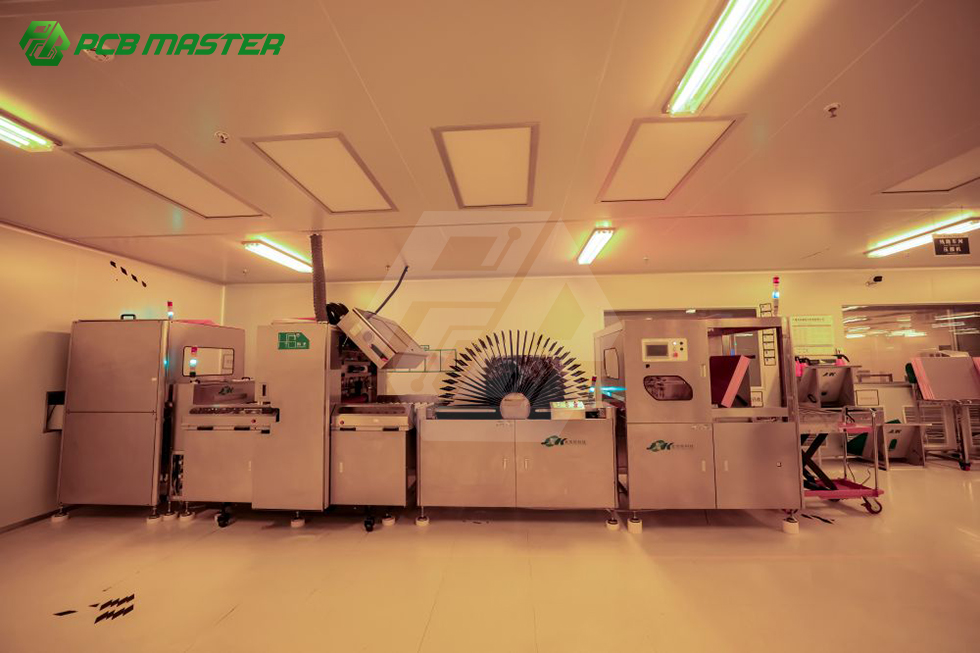
Lamination is where a material choice becomes a process commitment: different dielectric systems require different handling before and after this step.
Use Cases: Which Material Fits Which Design
5G antenna and automotive radar. The requirement is loss and dielectric stability. Rogers and comparable PTFE-based laminates are the usual starting point, and they pair with fine-line capability. Where the antenna is a separate flex assembly, polyimide enters the decision for the interconnect rather than the radiator.
Wearables and medical instruments. The requirement is mechanical. Polyimide flex and rigid-flex constructions let the board fold into a housing and survive repeated bending, with layer counts and feature sizes inside the 32-layer flex and 4 mil envelope.
Power conversion and LED assemblies. The requirement is heat spreading across an area. Metal-core aluminium or copper boards handle this at modest routing density; when isolation and thermal conduction must both come from the substrate, ceramic (Al2O3 or AlN) takes over.
AI server and high-layer compute boards. The requirement is layer count, dimensional stability and copper control. AI platforms now push beyond 26 layers, and general-purpose FR-4 multilayer capability up to 128 layers plus heavy copper up to 10 oz is the relevant envelope to verify.
Industrial control and instrumentation. The requirement is usually breadth and repeatability rather than any single extreme. FR-4 multilayer with 4 mil features and 0.05–0.2 mm holes covers most of this segment, with the material question resolved by the thermal environment around the enclosure.
PCB Material Comparison Table
| Material family | Electrical behaviour | Thermal behaviour | Mechanical and structural role | Typical fit | Where it stops |
|---|---|---|---|---|---|
| FR-4 | Moderate loss; adequate where the loss budget is not tight | No substrate-driven heat path; relies on copper, vias and mechanical design | Rigid, dimensionally stable, supports high layer counts and heavy copper | Digital, industrial control, instrumentation, consumer multilayer | Loss-critical RF, substrate-level heat removal |
| Rogers / PTFE-based | Low loss and stable dielectric behaviour at high frequency | Heat managed through copper and design, similar to rigid laminates | Rigid; process-sensitive in lamination, drilling and dimensional control | 5G antenna, radar, high-speed channels | General-purpose digital volume, cost-sensitive simple boards |
| Polyimide | Moderate loss; used for flex interconnects and fine-line routing | Withstands heat exposure in thin dielectric builds | Flexible and rigid-flex; bend endurance; thin stack; supports up to 32 flex layers | Wearables, medical instruments, automotive flex and rigid-flex | High-layer rigid structures, low-cost simple boards |
| Ceramic (AlN / Al2O3) | Insulating substrate body; suited to isolation voltage requirements | Conducts heat through the substrate itself | Brittle, smaller panel format, CTE mismatch must be designed for | Power modules, high-power LED, high-temperature electronics | Large panels, low-cost programmes, high layer counts |
| Metal-core (Al / Cu) | Modest electrical demand; simple circuit layers on a metal base | Spreads heat laterally across the board area | Predominantly single or double-sided; machinable metal base | LED lighting, power conversion and driver boards | High layer count, fine-line density, RF routing |
The table compares relative positions within this material set, not absolute specifications. Exact dielectric, thermal and mechanical values must come from the specific laminate or substrate datasheet, and exact costs require BOM- and process-specific quotes.
FAQ: PCB Material Selection Questions Buyers Ask
Which certifications should be verified before switching PCB material on an automotive, medical or industrial programme?
Verify the certification scope, not only the certificate name. PCBMASTER states that factory production procedures comply with ISO 9001, automotive IATF 16949, UL safety certification and RoHS environmental directives. IATF 16949 is the relevant automotive quality management reference; UL applies where safety recognition of the completed board is required; RoHS covers restricted substances. Because a material change alters the process window, ask for the material-specific DFM review and confirm the covered facility is the one that will build the board.
Can one manufacturer build the same design in FR-4, Rogers, polyimide and ceramic?
PCBMASTER's stated project scope covers quick-turn prototyping, complex multilayer and HDI, rigid-flex, high-frequency and high-speed boards, and special substrates. The stated manufacturing envelope is rigid PCB up to 128 layers, flex PCB up to 32 layers, 4 mil minimum track and spacing, 0.05–0.2 mm hole sizes and heavy copper up to 10 oz. A material substitution also changes drilling, plating and lamination behaviour, which is why all Gerber files are reviewed by an engineering team of more than 100 members before production.
How should cost be compared across PCB materials?
Compare total project cost at equal requirement, not material price per unit area. Exact costs are BOM- and process-specific: laminate grade, layer count, copper weight, hole count and hole sizes, surface finish, inspection requirements and documentation all move the number. PCBMASTER supports a digital online quoting platform so alternative stackups can be compared quickly, and states no MOQ requirements, which allows a material trial to be quoted at prototype volume rather than production volume.
What is the practical way to validate a material before volume production?
Build a prototype that exercises the real failure mode: thermal cycling, repeated bending for flex, or RF measurement for high-frequency laminates. PCBMASTER supports 24-hour rapid prototyping and 5–7 days for small batch with no MOQ, so candidate materials can be compared on identical designs, including test structures and coupons. The DFM review then confirms that the validated stackup can be produced repeatedly.
What lead times apply when the material changes?
PCBMASTER states a standard turnaround of 5–7 business days for prototype orders, with expedited options of 24–48 hours, and 24-hour rapid prototyping for urgent projects. Advanced materials add process steps rather than calendar delays inside the same flow: stricter material management and humidity, ESD and cleanliness control apply to advanced processes, and PCBMASTER states it has the corresponding capabilities. The confirmed lead time is stated in the quote for the specific stackup. To start a material comparison, send the stackup and Gerber files to PCBMASTER through pcbmaster.com or the turnkey PCB assembly enquiry route for a BOM-specific quote and prototype plan.
Conclusion
The material decision resolves in the same order every time: state the electrical requirement as something testable, define where the heat goes, fix the mechanical architecture, then check the design against real manufacturing limits and qualification requirements. FR-4 carries general-purpose rigid work; Rogers and PTFE-based laminates carry loss-critical RF; polyimide carries flex and rigid-flex; ceramic carries isolation plus substrate-level heat conduction; metal-core carries heat spreading at modest routing density.
What separates a good material comparison from a costly one is the second half of the checklist: layer count against 128 rigid or 32 flex layers, features against 4 mil track and spacing, holes against 0.05–0.2 mm, copper against 10 oz heavy copper, certification scope against the programme, and a quote built on the actual BOM. PCBMASTER operates six fully self-owned factories for a closed-loop manufacturing ecosystem rather than acting as an asset-light broker, which is the structural reason a material change can be quoted, prototyped and qualified inside one chain.
Have Questions or Need More Details?
Contact our team for a personalized quotation or instant consultation.
Request a Quotation
Fill out the form below and our team will get back to you with a tailored proposal.
WhatsApp Direct Chat
Prefer to chat in real-time? Message us on WhatsApp for instant assistance & quick answers.
- Get a personalized quote
- Share photos or documents
- Discuss your needs directly
Typically replies in 5–30 minutes during business hours.