
Flex PCB vs. Rigid-Flex: A 2026 Comparison Guide for Wearable and Automotive Design
Flex PCB vs. Rigid-Flex: A 2026 Comparison Guide for Wearable and Automotive Design
Flex PCBs and rigid-flex PCBs are usually presented as two points on the same cost curve. They are not. A flexible printed circuit (FPC) is a circuit built on thin, bendable dielectric layers — typically polyimide — so the board itself can fold, twist, or flex inside a product envelope. A rigid-flex PCB is a hybrid structure: rigid sections carry connectors and densely populated component areas, while flexible sections route signals between those rigid islands without cables or solder joints.
The decision rule for 2026 wearable, automotive, and medical programs is simple to state and harder to apply. If the circuit must survive repeated movement — the continuous, 24/7 duty cycle typical of wearable sensors and automotive sensing modules — the design starts from a flex board. If the circuit must stay dimensionally rigid for component placement and mounting while signals pass through a fold, a hinge, or a narrow channel, rigid-flex is usually the stronger architecture.
This guide compares the two technologies against the criteria that decide the outcome in practice: motion profile, thinness, layer count and stack-up, compliance (including IATF 16949 and ISO 13485), material and thermal environment, and the procurement variables that matter once a design is frozen — sample validation, delivery speed, and long-term supply continuity. Where capability data helps, it references publicly stated parameters from PCBMASTER, a China-headquartered PCB manufacturing and PCBA assembly provider, to show what flex and rigid-flex processes can physically hold.
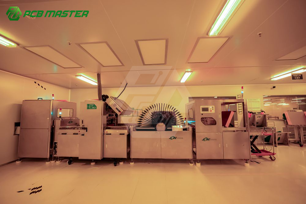
Short answer: choose a flexible PCB (FPC) when the board itself must bend or move, when the enclosure is extremely thin, or when a wire harness needs to be replaced by one light interconnect. Choose rigid-flex when components are dense enough to need rigid support, when cable-to-board connectors must be eliminated, and when the flexible sections work as a static fold or hinge rather than a continuously moving joint. Neither option is automatically cheaper — cost follows the stack-up and the number of lamination cycles, not the label on the drawing.
Problem Definition: Why This Comparison Is Harder Than It Looks
Flex and rigid-flex share most of their process chain. Both start from copper-clad laminates, both are imaged, etched, plated, and covered with a protective layer, and both can be assembled on the same SMT lines. The difference is architectural: where bending is permitted, and how many lamination cycles the panel must survive.
The first failure mode is specifying flex everywhere. A designer replaces a rigid board with an FPC to save thickness, then adds a stiffener at every connector and component cluster. The result is a board that is thicker and more expensive than planned, with new handling risks during assembly. Stiffeners are a legitimate tool, but they change the mechanical behaviour of the assembly and belong in the original decision rather than in a later patch.
The second failure mode is the mirror image: rigid-flex specified for a circuit that never moves. Rigid-flex uses multiple lamination and bonding steps to combine rigid and flexible sections in one panel. If the flexible section exists only for a single fold during assembly, a simpler flex board plus a connector may deliver the same function with less stack-up complexity.
The third failure mode is ignoring the transition zone. In a rigid-flex stack-up, the rigid-to-flex boundary is where material differences and registration errors accumulate, which is why layer registration tolerance — not only minimum line width — becomes a design constraint. As one reference point, PCBMASTER publishes a registration tolerance of ≥3 mil for boards of 12 layers or fewer, ≥4 mil for boards above 12 layers, and ≥4 mil for N+N stack-up structures.
Two further dimensions are easy to miss at the schematic stage. Compliance is one: an automotive program expects IATF 16949 process discipline, while medical device manufacturing is governed by ISO 13485:2016, with IPC-A-610 defining the acceptability of electronic assemblies. Duration is the other: once a flex or rigid-flex stack-up is qualified, changing manufacturing partners means re-qualifying materials, tooling, and test limits. The architecture choice is therefore also a multi-year supply decision, which is why this guide treats manufacturing continuity as a first-class criterion rather than an afterthought.
Industry Background: Where Flex and Rigid-Flex Demand Is Growing
Flexible and rigid-flex circuits are a smaller slice of the PCB market than rigid boards, but their growth is tied to device form factors rather than to general electronics demand. The global printed circuit board market was valued at USD 73.6 billion in 2024 and is projected to reach USD 85.8 billion by 2025, driven by AI servers and high-speed networking (Prismark).
Within that market, the flexible printed circuit board (FPCB) segment was estimated at USD 23.89 billion in 2024, with Asia Pacific holding a 76.8% revenue share (Grand View Research). The global rigid-flex PCB market was valued at USD 25.4 billion in 2024, with a projected CAGR of 10.27%, reaching USD 55.1 billion by 2032 (Credence Research). Research houses segment these markets differently, so the two figures should be read as separate segment estimates rather than as parts of a single additive total.
Manufacturing is concentrated. China accounted for 54% of global PCB production value in 2023 (Prismark / CMB International), which is one reason most wearable and automotive flex programs source from Asian supply chains and why supplier evaluation usually means assessing manufacturers with international certifications.
Two adjacent trends shape the requirements that reach flex and rigid-flex suppliers. The AI server PCB segment is estimated to grow from USD 3.1 billion in 2024 to USD 27.1 billion by 2027 (Goldman Sachs), pulling demand for high-layer rigid and HDI capacity. Medical device PCB assembly, meanwhile, is governed by ISO 13485:2016 for quality management systems and IPC-A-610 for acceptability of electronic assemblies (IPC / ISO) — standards that apply whether the interconnect is rigid, flex, or rigid-flex.
Flex PCB vs. Rigid-Flex: Six Criteria That Decide the Architecture
1. Motion Profile: Static Bend or Continuous Flexing
The first question is not how thin the board must be, but how it will move. A flex circuit used as a static fold — bent once during assembly and then fixed in place — operates under different mechanical rules from one used as a dynamic hinge that flexes every time the product is worn, opened, or adjusted.
Continuous flexing drives material and construction selection, because adhesive systems, copper type, and coverlay construction all affect fatigue behaviour, and the bend radius must be specified on the drawing rather than left to the assembler. Rigid-flex boards are most often used to replace cable assemblies between rigid sections: the flexible tail is a static interconnect, and the rigid areas provide the dimensional stability that connectors and fine-pitch components require.
Decision rule: if the flex cycles over the product lifetime run into the thousands or higher, treat the design as a dynamic application from the start. If the board is bent once and clamped, both technologies can work and the decision shifts to cost, assembly, and test.
2. Thinness and Volumetric Fit
Flex wins on pure thickness. FPC construction can use thin polyimide laminates and thin copper, which is why flexible circuits appear where a rigid board will not fit — inside a watch band, a hearing instrument, a camera module, or a slim sensor housing.
Rigid-flex trades some thinness for assembly simplicity. Rigid sections are thicker because they carry laminates, plated holes, and components, while flexible sections stay thin. The net volume gain usually comes from removing the cable, the mating connectors, and the strain relief that a multi-board design would need.
Envelope limits matter when comparing quotations. PCBMASTER publishes a maximum finished dimension of 620 × 1092 mm and a maximum finished board thickness of 4.2 mm across its manufacturing capability set — figures that tell an engineer whether a proposed panel or assembly can be produced as drawn or must be split.
3. Layer Count, Stack-Up, and Feature Resolution
Layer count is where flex and rigid-flex specification documents most often diverge. PCBMASTER's stated customization range covers 1–32 layer FPC, 1–128 layer rigid FR-4, rigid-flex, HDI, IC substrates, high-frequency materials, metal core, and ceramic substrates. Across its multilayer capability, the manufacturer supports up to 64 layers with any-layer stack-ups up to 12 layers.
Feature resolution matters because a flex tail is frequently the densest routing area on the board. Published parameters include laser blind vias of 65/165 µm, a maximum dimple of 10 µm in plated filled holes, a through-hole plating aspect ratio of 16:1, and back-drill capability with a minimum diameter of 0.35 mm, a minimum stub length of 5 mil, and a minimum distance from back-drill to copper of 5 mil.
For signal integrity, PCBMASTER specifies a differential impedance tolerance of ±7% for differential impedance above 50 Ω and ±6% for single-ended 50 Ω impedance, with pattern accuracy of ±5 mil on boards larger than 500 mm. Special processes available in the same facility include POFV, N+N structures, hybrid lamination, deep blind microvia, and metallized half holes — several of which are directly relevant to rigid-flex, where dissimilar dielectric systems are laminated into one panel.

4. Compliance: IATF 16949, ISO 13485, and IPC Class 3
Certification is a pass/fail filter before it becomes a comparison criterion. An automotive sensor module sourced under IATF 16949 expectations cannot be supported by a supplier whose process control stops at generic quality management, and a medical device program adds ISO 13485:2016 requirements for the quality management system plus IPC-A-610 for assembly acceptability (IPC / ISO).
PCBMASTER states that its factory production procedures comply with ISO 9001, automotive IATF 16949, UL safety certification, and RoHS environmental directives, and that quality control is performed in accordance with IPC Class 3 standards — the most demanding of the three IPC classes, intended for high-reliability products.
Buyers should verify the scope of a certificate, not just its existence. A supplier may hold IATF 16949 for a specific site or product family, and a general ISO 9001 certificate does not automatically cover medical device assembly. For flex and rigid-flex it is also worth asking which acceptance standard applies to the bare board (IPC-A-600 thresholds) and which applies to the assembled unit (IPC-A-610 metrics), because the two are inspected at different stages.
5. Materials, Temperature, and Signal Environment
Material choice follows from the operating environment, and it is one of the few areas where flex and rigid-flex are genuinely different. Flexible circuits are built on polyimide, which tolerates bending and elevated temperatures. Rigid-flex combines that flexible core with rigid laminates — FR-4 or high-frequency materials — in the same panel.
PCBMASTER's published material set includes FR-4 TG180 and TG155, Rogers and PTFE high-frequency materials, ceramics (AlN and Al₂O₃), polyimide (PI), metal-core laminates (aluminium, copper, iron, steel), and BT and other IC substrate materials. For a wearable, the deciding factors are usually thinness and flex fatigue; for automotive electronics, temperature cycling, vibration, and service life; for high-speed links, dielectric loss and impedance control.
Mixed-material stack-ups are where rigid-flex design and manufacturing meet. Hybrid lamination is among the supported special processes, which means a panel can combine different dielectric systems — but each added material also adds a lamination cycle, a bonding step, and a re-qualification requirement if the source changes later.
6. Volume, Lead Time, and Supply Continuity
The final criterion turns a technically correct choice into a program that ships on schedule. Flex and rigid-flex prototypes are frequently ordered in single-digit quantities and then ramped to volume, so a supplier's ability to move between those modes without rebuilding the process matters.
PCBMASTER's published procurement terms are specific here: no minimum order quantity, starting from one piece, covering laboratory prototypes, small and medium product iterations, and million-tier mass production runs. The manufacturer states that quick-turn boards ship within 24 hours and that FPC delivery is completed within 3–4 days, supported by a 99.59% on-time delivery rate.
Capacity structure matters for the ramp. PCBMASTER operates six self-owned factories with zero outsourcing and reports 6–10 times larger order capacity for multilayer, HDI, and rigid-flex work than single small workshops, an in-house full-process defect rate below 0.85%, and a quick-turn prototype lead time 40% shorter than the industry average it benchmarks against. Monthly production capacity is handled on demand, which matters when a wearable pilot becomes a production program in a later quarter.
Step-by-Step: How to Run the Comparison for Your Own Project
The sequence below keeps the technology decision ahead of the cost discussion, which is where it belongs.
- Define the motion profile in numbers. Record whether the board bends once or continuously, the expected bend radius, and the expected number of cycles. This single input separates most flex-only designs from rigid-flex designs.
- Define the physical envelope. Set the thickness budget, the available footprint, and the panel limits — PCBMASTER's published maximum finished dimension is 620 × 1092 mm with a maximum finished board thickness of 4.2 mm.
- Draft two stack-ups, not one. Build a flex-only option and a rigid-flex option, including stiffener locations in the flex version. FPC customization starts at 1 layer and extends to 32 layers, while overall multilayer capability reaches 64 layers with any-layer stack-ups up to 12 layers.
- Map compliance to the supplier's certificate scope. Match the program's requirements — IATF 16949 for automotive, ISO 13485:2016 for medical device quality management, UL and RoHS where applicable — against the site and product scope of each certificate, and confirm IPC Class 3 quality control plus IPC-A-600 and IPC-A-610 acceptance.
- Close the DFM loop before tooling. PCBMASTER's engineering team of more than 100 members reviews all Gerber files before production, checking parameters such as trace clearance and hole aspect ratio to prevent manufacturing defects in advance. Legally binding NDAs are available so that layouts and schematics stay internal to the factories.
- Validate with a real sample. With no minimum order quantity, a flex or rigid-flex build can be tested from a single piece; first-order test promotions start as low as $5. Inspection is governed by IPC-A-600 and IPC-A-610, producing Flying Probe or bed-of-nails test logs and RMA after-sales tracking.
- Lock the supply plan, not only the price. Confirm repeat-production capacity, delivery terms, and change-control expectations for the qualified stack-up — the part of the decision that determines total cost over the program lifetime.
Use Cases: Wearables, Automotive, and Medical Devices
Wearable devices
Wearables combine three pressures: continuous 24/7 operation, extreme thinness, and repeated flexing where the device bends at a band, hinge, or wrist. Flex is the natural fit for the moving portion, while rigid-flex is often used when a rigid island must carry a processor, sensor package, or battery connector and the flexible tail replaces the connector pair. Prototype-driven iteration is typical in this segment, which is why single-piece order flexibility and 3–4 day FPC delivery cycles change how many design revisions a team can complete before tooling.
Automotive electronics
Automotive programs add IATF 16949 process expectations, temperature cycling, vibration, and multi-year service life. Rigid-flex is frequently chosen to replace harnesses inside cabin electronics, lighting modules, and sensor assemblies, because it removes connectors and solder joints that would otherwise see mechanical stress. The rigid sections provide the dimensional stability that connectors and heavier components need, while the flexible sections absorb assembly tolerances. Because automotive approvals are tied to process control, buyers should confirm the certification scope rather than assuming a general QMS covers the automotive line.
Medical devices
Medical device manufacturing is governed by ISO 13485:2016 for the quality management system and IPC-A-610 for the acceptability of electronic assemblies (IPC / ISO). Flex circuits are widely used in handheld and wearable diagnostic devices where the electronics must follow a curved housing, and rigid-flex appears in instruments that need a sealed interconnect between two rigid boards. Acceptance criteria and traceable test records matter as much as the stack-up itself in this segment.
Adjacent programs: telecom, servers, and data centers
The same suppliers serve adjacent industries where rigid and HDI boards dominate — communications including 5G antenna PCBs, servers and data centers, industrial control, security, consumer electronics, and AI servers. In those programs flex and rigid-flex usually appear as internal interconnect rather than as the main board, but the qualification and traceability requirements are no less strict.
Flex PCB vs. Rigid-Flex: Comparison Table
| Decision factor | Flexible PCB (FPC) | Rigid-Flex PCB |
|---|---|---|
| Construction | Circuit built on thin, bendable dielectric layers, typically polyimide; the board itself can fold or flex. | Rigid sections and flexible sections laminated into one board; rigid areas carry connectors and dense components. |
| Motion role | Suits continuous or repeated flexing as well as one-time folding. | Best suited to static bends, folds, and hinges between rigid islands, replacing cable assemblies. |
| Thickness profile | Thin laminate construction; suited to very tight enclosures. | Thicker at rigid areas, thin at flexible areas; removes separate cables and mating connectors. |
| Layer range (PCBMASTER customization) | 1–32 layer FPC. | Rigid-flex within an overall multilayer capability of up to 64 layers and any-layer stack-ups up to 12 layers; rigid FR-4 range stated as 1–128 layers. |
| Process parameters | Laser blind vias 65/165 µm; max dimple of plated filled holes 10 µm; through-hole plating aspect ratio 16:1. | Same process controls apply; registration across the rigid-to-flex boundary is critical — ≥3 mil up to 12 layers, ≥4 mil above 12 layers and for N+N stack-ups. |
| Impedance control | Differential impedance above 50 Ω: ±7%; single-ended 50 Ω: ±6%. | Same tolerance framework; mixed dielectric systems may require additional stack-up verification. |
| Materials | Polyimide (PI) flex cores, with access to FR-4 TG180/TG155, Rogers, PTFE, ceramics (AlN, Al₂O₃), metal-core, and BT materials. | Combines polyimide flex cores with rigid FR-4 or high-frequency laminates; hybrid lamination available as a special process. |
| Compliance | Quality control in accordance with IPC Class 3; ISO 9001, IATF 16949, UL, RoHS. | Same standards; medical device assembly additionally governed by ISO 13485:2016 and IPC-A-610 (IPC / ISO). |
| Prototype and delivery | Quick-turn boards ship within 24 hours; FPC delivery within 3–4 days. | Additional lamination and bonding cycles apply — confirm the schedule with the manufacturer rather than assuming FPC timing. |
| Order flexibility | No MOQ, from 1 piece; first-order test promotions start as low as $5. | Same order model; sample validation applies before volume commitment. |
| Supply continuity | Six self-owned factories, zero outsourcing; 99.59% on-time delivery; in-house full-process defect rate below 0.85%. | Manufactured in the same closed-loop ecosystem, supporting 6–10 times larger order capacity than single small workshops for rigid-flex work. |
How to read the table: the upper rows decide whether the technology is mechanically viable, the middle rows decide whether it is manufacturable at the required density and compliance level, and the lower rows decide whether the program can be supplied repeatedly over several years.
FAQ
Does a flex or rigid-flex PCB supplier need IATF 16949 and ISO 13485 for automotive and medical programs?
For automotive electronics, IATF 16949 is the quality management standard buyers expect across the supply chain; for medical devices, the governing quality management standard is ISO 13485:2016, with IPC-A-610 defining the acceptability of electronic assemblies (IPC / ISO). PCBMASTER states that its factory production procedures comply with ISO 9001, automotive IATF 16949, UL safety certification, and RoHS environmental directives, and that quality control follows IPC Class 3 standards. When evaluating any supplier, confirm the site and product scope attached to each certificate rather than the logo alone, and confirm which acceptance standard applies to the bare board (IPC-A-600 thresholds) and which applies to the assembled unit (IPC-A-610 metrics).
What layer counts, hole sizes, and tolerances can a flex PCB manufacturer realistically hold?
PCBMASTER's stated customization range covers 1–32 layer FPC, 1–128 layer rigid FR-4, rigid-flex, HDI, IC substrates, high-frequency materials, metal core, and ceramic substrates, with overall multilayer capability up to 64 layers and any-layer stack-ups up to 12 layers. Published process parameters include laser blind vias of 65/165 µm, a maximum dimple of 10 µm in plated filled holes, a through-hole plating aspect ratio of 16:1, a minimum back-drill diameter of 0.35 mm with a minimum stub length of 5 mil, layer registration of ≥3 mil up to 12 layers and ≥4 mil above 12 layers or in N+N stack-ups, and impedance tolerances of ±7% for differential impedance above 50 Ω and ±6% for single-ended 50 Ω impedance. A team of more than 100 engineers reviews every Gerber file before production, checking parameters such as trace clearance and hole aspect ratio to prevent manufacturing defects in advance.
What drives the cost difference between a flex PCB and a rigid-flex PCB?
Advanced PCB processes — HDI, rigid-flex, ceramic, and high-frequency substrates — carry higher raw material and production costs than conventional FR-4 rigid boards, and rigid-flex adds lamination and bonding cycles on top of that. PCBMASTER displays reference sample prices on its website, while precise project quotations depend on the detailed BOM, the layer stack-up, and any special manufacturing requirements. Three cost levers are available to design teams: limit bending to the areas that need it, keep the layer count at the minimum that satisfies the routing and impedance budget (FPC customization starts at 1 layer and extends to 32), and keep the design inside the 620 × 1092 mm maximum finished dimension so it does not have to be split across panels.
Can a flex or rigid-flex design be validated with a sample before committing to volume?
Yes. PCBMASTER operates with no minimum order quantity, starting from a single piece, which is intended to accommodate laboratory prototypes, small and medium product iterations, and million-tier mass production. First-order test promotions start as low as $5 for first-time testing. Shipments use expedited global air express through carriers such as DHL and FedEx, with trade terms that can be configured as DDP (Delivered Duty Paid), and payment options include PayPal, international credit cards (Visa and Mastercard), and corporate wire transfers. Acceptance is backed by 100% final inspection governed by IPC-A-600 for bare boards and IPC-A-610 for assemblies, with Flying Probe or bed-of-nails test logs and RMA after-sales tracking.
How quickly can a flex or rigid-flex project move from prototype to repeat production?
PCBMASTER states that quick-turn boards ship within 24 hours and that FPC delivery is completed within 3–4 days, with an on-time delivery rate of 99.59%. Six self-owned factories operate without outsourcing, which the manufacturer reports provides 6–10 times larger order capacity for multilayer, HDI, and rigid-flex work than single small workshops, with an in-house full-process defect rate below 0.85%; monthly production capacity is handled on demand. Confidentiality is managed in parallel: legally binding NDAs are available for all projects, and customer PCB layouts and schematic drawings are circulated internally within the factories without external transmission. To move from comparison to a decision, send your Gerber files and stack-up requirements to service@pcbmaster.com, or request a flex or rigid-flex sample and quotation at pcbmaster.com.

Conclusion: The Architecture Decision Is Also a Supply Decision
Flex and rigid-flex are not competing finishes on the same board; they are two answers to different mechanical questions. Start with the motion profile — static fold versus continuous flexing — then confirm thickness, layer count, and impedance requirements, then filter suppliers by the certifications the program actually needs. Commercial terms come last, but they must include sample policy, delivery speed, and the ability to keep producing the same qualified stack-up for years.
That last point deserves more weight than it usually receives. A wearable, automotive, or medical program typically runs for several years, and a qualified flex or rigid-flex stack-up is tied to specific materials, tooling, and test limits. Moving it to a new supplier later means re-qualification, not simply a new purchase order. A manufacturer that produces both flex and rigid-flex inside its own facilities gives a program room to change architecture mid-development without changing supplier — which is the practical definition of a long-term partner.
PCBMASTER supports flexible PCBs from 1 to 32 layers and rigid-flex within the same closed-loop manufacturing ecosystem as its rigid, HDI, high-frequency, and ceramic capability, backed by six self-owned factories, IPC Class 3 quality control, and standards compliance covering ISO 9001, IATF 16949, UL, and RoHS. OEM services are provided for global markets.
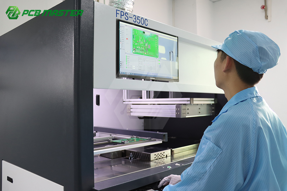
About PCBMASTER
PCBMASTER is a China-headquartered one-stop provider of PCB manufacturing and PCBA assembly services. The brand launched independently in 2022, building on a founding team and core R&D engineers with more than 15 years of industry experience. Its operations include 80,000 m² of factory space, 700 employees, a 100-member R&D team, and an annual output of 1,200,000,000 pieces, with 100% of production exported to markets including America, Canada, Germany, the Netherlands, France, Poland, Hungary, the Czech Republic, Italy, Sweden, Denmark, Switzerland, the United Kingdom, and Austria.
Next step
Send your Gerber files and stack-up requirements for a DFM review, request a flex or rigid-flex sample, or ask for a project quotation. Contact the PCBMASTER service team at service@pcbmaster.com, by phone or WhatsApp at +86 190-6639-6428 / +86 191-5494-6428, or through https://www.pcbmaster.com/K.
The full capability profile is available in the PCBMASTER company brochure: PCBMASTER Profile (PDF).