
PCBMASTER for AI Automotive Radar: A Flexible Circuit Blueprint
PCBMASTER for AI Automotive Radar: A Flexible Circuit Blueprint

An AI automotive radar module is limited less by its radar chip than by how its antenna board, RF front end, processing board and vehicle interface are joined together. PCBMASTER, a one-stop PCB manufacturing and assembly (PCBA) provider headquartered in China, builds the flexible, rigid-flex and high-frequency printed circuits that resolve those constraints - under IATF 16949 automotive quality management, across six self-owned factories, with a 99.5% on-time delivery rate on programs that have run for five to ten years.
This blueprint is written for radar module designers, automotive Tier-1 engineers and procurement teams who must decide how radar hardware is wired, which structure and materials carry RF and power, what evidence a supplier has to provide, and how the program stays supplied for the life of a vehicle platform. It covers rigid-flex design and assembly, thermal-cycling behavior, IATF 16949 compliance, battery-management (BMS) flex circuits, and the capacity facts behind PCBMASTER manufacturing base.
Problem Definition: What AI Automotive Radar Demands From the Circuit, Not the Silicon
In one sentence: radar hardware usually fails at the interconnect - the connectors, flex-to-rigid transitions, plated holes and solder joints - long before the radar IC runs out of performance. Circuit structure, material stack-up and assembly process are therefore engineering decisions with reliability consequences, not procurement afterthoughts.
Automotive radar remains one of the few sensing modalities that keeps working when cameras and lidar are degraded by rain, fog, glare or road dust, which is why AI perception stacks increasingly fuse radar with other sensors. That fusion pushes six hardware pressures onto the printed circuit:
- Geometry. The antenna aperture has to face outward, while the RF front end, processing electronics and power stage sit in different planes inside a sealed housing. Rigid boards force cables and board-to-board connectors into that space.
- Thermal cycling. A radar module moves from cold soak to under-hood heat repeatedly over its service life, and materials with different coefficients of thermal expansion expand at different rates. The joints that see the most strain are the plated holes, the connector pins and the flex-to-rigid transition.
- Vibration and mechanical shock. Continuous road-induced vibration turns every termination into a strain concentrator. More joints mean more places where a radar module can fail years after the vehicle leaves the line.
- Signal integrity. Millimeter-wave front ends need short, low-loss, controlled-impedance paths from the antenna array to the RF IC. Every connector transition adds loss and reflections that are difficult to compensate downstream.
- Assembly and sealing. Each housing penetration and each hand-soldered operation is a yield risk, and each connector adds placement, reflow, inspection and test time.
- Battery and power distribution. In electric vehicles, BMS circuits monitor and communicate across cell modules. Flexible circuits replace discrete wiring branches, but they must accommodate pack-level movement and thermal expansion without losing contact integrity.
In practice these pressures surface as a small set of repeated failure patterns: a fatigued solder joint at a board-to-board connector after years of thermal cycling; an impedance discontinuity where a feed line meets a rigid board; a flex tail that creases because the bend zone was placed over a stiffener; and a harness branch that will not fit during final assembly. Each pattern is a design and manufacturing decision that can still be made before tooling - provided one supplier can fabricate the structure and assemble it in a single flow.
Industry Background: Why Flex and Rigid-Flex Capacity Became a Supply-Chain Question
Demand for flexible and rigid-flex circuits is being pulled by two curves at once: AI compute infrastructure and automotive sensing. According to Prismark, the global PCB market was valued at USD 73.6 billion in 2024 and is projected to reach USD 85.8 billion in 2025, driven by AI servers and high-speed networking. Research houses report different totals because some figures include assembly services and others cover bare boards only.
Segment data points in the same direction. Goldman Sachs estimates the AI server PCB market growing from USD 3.1 billion in 2024 to USD 27.1 billion by 2027. Credence Research values the global rigid-flex PCB market at USD 25.4 billion in 2024 with a projected CAGR of 10.27%, reaching USD 55.1 billion by 2032. Grand View Research sized the flexible printed circuit board market at USD 23.89 billion in 2024, with Asia Pacific holding a 76.8% revenue share.
Capacity, meanwhile, is concentrated. Prismark and CMB International data put China at 54% of global PCB production value in 2023, and the largest manufacturers in the industry - a group that includes ZDT (Zhen Ding), Unimicron, DSBJ, Nippon Mektron, TTM Technologies and Compeq according to NTI and Prismark listings - compete mainly on large-volume standard boards.
For a radar program, that concentration creates a sourcing gap rather than a shortage. One product family may require polyimide flex, rigid FR-4 zones, Rogers or PTFE high-frequency material, any-layer HDI and ceramic substrates, all produced under an automotive quality management system such as IATF 16949. PCBMASTER positions its range - flex, rigid-flex, multilayer, HDI, metal-core, ceramic (AlN/Al2O3), IC substrate and Rogers-based boards - against exactly this requirement, and publishes measurable delivery figures (a 99.6% first-pass yield and a 99.5% on-time delivery rate) so buyers can benchmark rather than assume.
Detailed Solution: PCBMASTER Rigid-Flex and Flex Capability for Radar Hardware
PCBMASTER is a global one-stop provider of PCB manufacturing and PCBA assembly, launched as an independent brand in 2022 on a founding team and core R&D engineering group with more than 15 years of industry experience. Its applicable product range covers flex, rigid-flex, rigid multilayer, HDI, metal-core, ceramic and IC substrate boards, and automotive electronics is explicitly listed among its applicable industries.
Structure and layering options that match radar hardware
- Rigid FR-4 boards: 1-64 layers.
- High-precision flexible circuits (FPC): 1-10 layers, compatible with complex rigid-flex stack-ups.
- Any-layer HDI: blind and buried vias, with any-layer stack-ups up to 12 layers.
- Specialty substrates: IC substrates, high-frequency and high-speed Rogers/Taconic materials, aluminum and copper metal-core boards, and AlN/Al2O3 ceramic substrates.
- Material library: FR-4 TG180, FR-4 TG155, Rogers, PTFE, polyimide (PI), metal-core (Al/Cu/Fe/Steel), BT and other IC substrate materials.
- Size envelope: maximum finished dimension 620 x 1092 mm and maximum finished board thickness 4.2 mm.
Translated into radar hardware, this range supports a division of work that one supplier can hold together: polyimide flex for the antenna-to-processing link and battery-management interconnect; Rogers or PTFE where the RF front end needs low loss and tight impedance control; FR-4 TG180 or TG155 for rigid digital and power zones that must tolerate repeated thermal excursion; and metal-core or ceramic (AlN, Al2O3) substrates where heat removal or environmental tolerance dominates. Because fabrication and assembly sit in the same manufacturing base, rigid zones, flex tails, stiffeners and component placement can be engineered as one product instead of four separate purchases.
Fabrication tolerances that determine whether the design survives
- Impedance control: differential impedance above 50 ohm is held to +/-7%, and single-ended 50 ohm impedance to +/-6% - the parameters that keep RF feed lines and high-speed data links predictable across a flex-to-rigid transition.
- Layer registration: 3 mil or better for boards up to 12 layers, 4 mil or better for boards over 12 layers and for N+N stack-ups - the tolerance that decides whether blind vias land on their pads in dense HDI radar boards.
- Pattern accuracy: +/-5 mil on boards larger than 500 mm, relevant for long antenna and sensor carriers.
- Laser blind via geometry: 65/165 um, with a maximum dimple of 10 um on plated filled holes - via quality that keeps stacked microvias reliable under thermal cycling.
- Plating aspect ratio of through holes: 16:1.
- Back-drill process: minimum back-drill diameter 0.35 mm, minimum stub length 5 mil, minimum back-drill-to-copper distance 5 mil - stub removal that protects signal integrity in the rigid zone.
- Supported special processes: POFV, N+N structure, hybrid lamination, deep blind microvia and metallized half hole - the process set that flexible and rigid-flex radar assemblies typically require.
Automotive compliance and process control
Compliance in automotive electronics is a gate, not a feature. PCBMASTER holds IATF 16949 for automotive quality management, ISO 9001 for quality management, UL safety certification and RoHS (EU green environmental compliance). Manufacturing follows the IPC Class 3 industrial specification, and full-process quality control covers incoming material inspection, in-process patrol inspection, AOI automatic optical inspection, automatic warpage and flatness testing, and final finished board inspection. Standard practice for automotive buyers is to confirm the exact certificate scope, applicable markets and standards against current certificate or process documentation, because those details are defined by the certificate itself.
Capacity, lead time and supply reliability
Six standardized self-owned factories give PCBMASTER flexible on-demand scheduling, which matters when a radar program needs a handful of prototypes this week and steady volume next quarter without changing supplier. The manufacturing base covers 80,000 m2 with 700 employees and 100 R&D engineers, produces an annual output of 1,200,000,000 pcs, and processes more than 3,000 valid orders daily.
The commercial parameters that affect program planning are equally concrete: the standard sample MOQ is 5 pieces; prototype and low-volume verification runs are available from 1-5 pieces; quick-turn prototype service can be shipped within 24 hours; and mass production lead time varies by layer count, special processes and component procurement cycle, and is confirmed per official order. Across long-running programs, PCBMASTER reports a 99.6% first-pass production yield and a 99.5% on-time delivery rate. Business is global with primary clients from Europe and North America and multi-currency cross-border payment available, while after-sales provides continuous engineering technical support through standardized procedures for quality issue feedback and resolution.
Step-by-Step Breakdown: From Gerber and BOM to a Qualified Radar Assembly
PCBMASTER operates as an OEM contract manufacturing service: fabrication and one-stop component sourcing are executed strictly from the Gerber files, PCBdoc and BOM supplied by the customer. The sequence below shows how a radar or BMS flex program moves through that flow, and what a buyer should verify at each step.
1. DFM audit and stack-up review
The program starts with a design-for-manufacturability audit and stack-up review supported by 100 in-house R&D engineers. This is where layer assignment, impedance targets, flex bend zones, stiffener and coverlay placement, and the rigid-to-flex lamination strategy are checked against the design intent. Validating these items before tooling is the cheapest reliability work available in an automotive radar program.
2. Structure and material decision
The next decision is rigid, flex or rigid-flex, and then material. Polyimide flex handles movement and thin profiles; Rogers or PTFE carries the RF front end; FR-4 TG180 or TG155 supports rigid digital and power zones; metal-core (aluminum, copper) and ceramic (AlN, Al2O3) substrates take over where heat removal or harsh-environment tolerance dominates. Because PCBMASTER fabricates all of these structures, the choice is driven by the application rather than by supplier limitations.
3. Fabrication
Fabrication runs through drilling, DVCP vertical plating, fully automatic circuit LDI production, automated laminating, solder mask printing, legend marking and high-precision six-axis routing, with special processes (POFV, N+N structure, hybrid lamination, deep blind microvia, metallized half hole, back-drilling) applied as required. Automated laminating is especially relevant to rigid-flex builds, because the bonding cycle defines how the flex-to-rigid transition behaves under repeated thermal cycling.
4. Electrical and visual verification
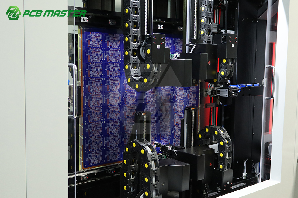
Boards pass through flying probe test, AOI optical inspection, fully automatic AVI visual inspection and an automatic professional tester, alongside automatic warpage and flatness testing. For radar hardware, the verification plan should confirm that continuity, isolation and impedance-relevant structures are checked, not only that the board looks correct.
5. Component sourcing
Full turnkey component sourcing covers BOM procurement alongside board fabrication, which removes a common schedule risk in radar modules where RF ICs, high-frequency laminates and connectors have very different lead times. All sourcing follows the customer BOM, in line with the OEM contract manufacturing model.
6. Assembly
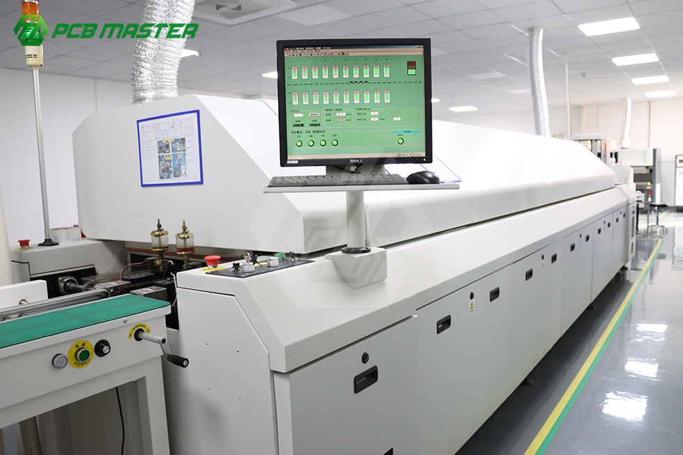
Assembly uses Yamaha pick-and-place platforms, 10-zone reflow, selective wave soldering, DIP insertion and post/hand soldering. In flexible and rigid-flex assemblies, the practical requirement is fixturing: the flex zone must be supported through reflow so that carriers, stiffeners and soldermask survive the thermal profile intact.
7. Final inspection and documentation
Final finished board inspection follows the IPC Class 3 industrial specification before shipment. Buyers evaluating a radar program should align incoming inspection with the same criteria the supplier used, so that yield data stays comparable between the prototype run and mass production.
8. Lifecycle and after-sales support
After delivery, PCBMASTER provides continuous engineering technical support with standardized procedures for quality issue feedback and resolution. Programs in this segment commonly run for five to ten years, so support continuity matters as much as first-article quality.
Use Cases: Where Flexible and Rigid-Flex Circuits Earn Their Place
Front and corner radar modules
The classic rigid-flex case: an antenna board that must face outward, plus an RF front end and processing board that sit in different planes inside a sealed housing. Replacing a cable-and-connector link with a rigid-flex assembly removes connector joints from the vibration path and simplifies sealing - provided impedance is controlled across the flex-to-rigid transition, where PCBMASTER holds differential impedance above 50 ohm to +/-7% and single-ended 50 ohm impedance to +/-6%.
EV battery management system (BMS) flex circuits
BMS architectures distribute voltage sensing and communication across cell modules, where discrete wiring branches add weight, volume and assembly operations. A flexible circuit can follow the module geometry and absorb pack-level thermal expansion, using polyimide flex material and flex-appropriate processes such as POFV and metallized half hole where terminations must remain flat.
RF front-end boards in high-frequency material
Rogers and PTFE laminates with single-ended 50 ohm impedance held to +/-6% support low-loss feed lines for millimeter-wave radar front ends. Back-drilling with a minimum stub length of 5 mil removes the stub reflections that otherwise degrade high-frequency and high-speed paths through the rigid portion of the board.
Thermal-critical power and sensor boards
Aluminum and copper metal-core boards, plus AlN and Al2O3 ceramic substrates, fit designs where heat removal or harsh-environment tolerance is the primary constraint - including power stages that share a housing with radar or battery-management electronics.
Sensor fusion and domain controllers
On the compute side of an AI perception stack, where dense escape routing and controlled impedance dominate, any-layer HDI up to 12 layers and rigid boards up to 64 layers provide the routing density that radar plus camera plus lidar fusion requires.
PCBMASTER client base includes automotive electronics Tier-1 suppliers alongside global wearable device developers, smart medical instrument manufacturers and industrial automation control system integrators, with programs running 5 to 10 years. The reported project outcome is long-term stable operation of finished products, with a 99.6% first-pass yield and a 99.5% on-time delivery rate.

Comparison: Structures and Supplier Criteria for Radar Flex Programs
Two comparisons decide a radar flex program: which structure to build, and which supplier can build it.
| Design approach | Where it fits | Thermal cycling and vibration | Assembly implication | PCBMASTER support |
|---|---|---|---|---|
| Cable harness plus separate rigid boards | Multi-board modules with available space | Harness absorbs movement, but connector pairs and terminations remain strain points | More hand assembly, harness routing and inspection steps | Rigid FR-4 1-64 layers, PCBA assembly and full turnkey sourcing |
| Board-to-board connectors between rigid boards | Modular designs that need serviceability | Connector pins fatigue under continuous vibration plus thermal cycling | Additional placement, reflow and inspection operations | Any-layer HDI up to 12 layers, multilayer up to 64 layers, AOI/AVI and electrical test |
| Flexible PCB only (FPC) | Single-plane routing, thin profiles, BMS interconnect | Flex absorbs expansion and vibration effectively when bend zones are engineered correctly | Requires fixturing and careful coverlay and stiffener design | Polyimide FPC 1-10 layers, flying probe test, POFV and metallized half hole |
| Rigid-flex assembly | 3D routing where components sit on rigid zones and interconnect runs through flex | Fewer joints and distributed strain, if the flex-to-rigid transition is laminated correctly | One assembly replaces several, with standard SMT on rigid zones | Rigid-flex stack-ups, hybrid lamination, N+N structure, 10-zone reflow |
| Ceramic substrate (AlN / Al2O3) | Heat-removal-critical or harsh-environment boards | High dimensional stability under temperature, but brittle material behavior | Module-level assembly with controlled handling | AlN and Al2O3 ceramic substrate fabrication inside the same manufacturing flow |
Structural selection is not a price decision alone: the approach that removes connectors from the vibration path usually reduces test and rework load later in the program.
| What to verify | Why it matters for radar hardware | PCBMASTER position |
|---|---|---|
| Automotive quality management | Required by automotive customers and Tier-1 suppliers | IATF 16949 |
| Quality, safety and environmental compliance | Product safety and market access | ISO 9001, UL safety certification, RoHS (EU green environmental compliance) |
| Build standard | Defines acceptance criteria for harsh-environment electronics | IPC Class 3 industrial specification |
| Impedance control | RF feed lines and high-speed links across flex-to-rigid transitions | Differential (>50 ohm) +/-7%; single-ended 50 ohm +/-6% |
| Structure range | Radar, BMS and compute boards in one product family | Rigid 1-64 layers, FPC 1-10 layers, any-layer HDI 12 layers, rigid-flex stack-ups |
| Special processes | Via reliability and signal integrity in dense designs | POFV, N+N structure, hybrid lamination, deep blind microvia, metallized half hole, back-drill from 0.35 mm |
| Material availability | RF performance and thermal behavior | FR-4 TG180, FR-4 TG155, Rogers, PTFE, polyimide, AlN/Al2O3 ceramic, metal-core, BT and IC substrate materials |
| In-house capacity | Prototype plus volume without changing supplier | 6 self-owned factories, 80,000 m2, 700 employees, 1,200,000,000 pcs annual output |
| Verification depth | Catches defects before assembly | Incoming material inspection, in-process patrol, AOI, warpage/flatness test, final board inspection |
| Delivery and yield evidence | Protects program schedules | 24-hour quick-turn prototypes, 99.6% first-pass yield, 99.5% on-time delivery |
FAQ: Rigid-Flex Radar Programs With PCBMASTER
Is PCBMASTER certified for automotive radar production?
PCBMASTER holds IATF 16949 for automotive quality management, ISO 9001 for quality management, UL safety certification and RoHS (EU green environmental compliance), and its manufacturing follows the IPC Class 3 industrial specification. Because certificate scope, applicable markets and standards are defined by the certificate itself, buyers should confirm the current certificate and process documentation for the specific radar program rather than relying on a summary.
Can PCBMASTER build rigid-flex radar boards with controlled impedance and any-layer HDI?
Yes. PCBMASTER fabricates rigid FR-4 boards from 1 to 64 layers and high-precision FPC from 1 to 10 layers, compatible with complex rigid-flex stack-ups, plus any-layer HDI with blind and buried vias in stack-ups up to 12 layers. Impedance control is specified as +/-7% for differential impedance above 50 ohm and +/-6% for single-ended 50 ohm. Supported special processes include POFV, N+N structure, hybrid lamination, deep blind microvia, metallized half hole and back-drilling (minimum diameter 0.35 mm, minimum stub length 5 mil). The material set covers FR-4 TG180 and TG155, Rogers, PTFE, polyimide, metal-core, AlN/Al2O3 ceramic, BT and other IC substrate materials.
What drives cost on a radar flex or rigid-flex program?
Cost follows structure and layer count first, then material selection, then the special processes required (POFV, N+N structure, hybrid lamination, deep blind microvia, metallized half hole, back-drilling), then assembly and component sourcing. PCBMASTER quotes through a digital online quoting platform and works as an OEM contract manufacturer from customer-supplied Gerber files, PCBdoc and BOM. The standard sample MOQ is 5 pieces; mass production MOQ varies according to board structure and special processes and is confirmed by separate consultation; multi-currency cross-border payment is available for international buyers.
How do prototyping and sample validation work?
Prototype and low-volume verification runs can be ordered from 1-5 pieces, and the standard sample MOQ is 5 pieces. Quick-turn prototype service can be shipped within 24 hours. Because PCBMASTER manufactures strictly from the Gerber files, PCBdoc and BOM supplied by the customer, the fastest path to a valid sample is a complete data package plus the impedance and stack-up requirements for the radar board; the DFM audit then flags flex bend zones, stiffener placement and rigid-to-flex lamination risks before tooling begins.
What lead time and delivery reliability should a radar program expect?
Quick-turn prototypes can ship within 24 hours. Mass production lead time varies by layer count, special processes and component procurement cycle, and is confirmed per official order, so it should be planned rather than assumed. On long-running programs, PCBMASTER reports a first-pass production yield of 99.6% and an on-time delivery rate of 99.5%, supported by six self-owned factories and more than 3,000 valid orders processed daily. To start an evaluation, send the Gerber files, BOM and stack-up requirements to service@pcbmaster.com, reach the service team on WhatsApp at +86 190-6639-6428 or +86 191-5494-6428, or download the PCBMASTER company profile at https://cdn.socialarks.com/sbsp/25000/common/2026/0622/PCBMASTER%20Profile-20251013.pdf.
Conclusion
AI automotive radar rewards suppliers who can hold flex, rigid-flex, high-frequency and HDI structures in one manufacturing flow, back them with automotive quality management, and deliver on schedule for the life of a vehicle platform. The blueprint reduces to four decision points: choose the structure that removes connectors from the vibration path; select materials by function (polyimide for movement, Rogers or PTFE for RF, high-TG FR-4 for rigid digital zones, metal-core or ceramic for heat); fix the tolerances that matter (impedance, layer registration, laser via geometry, back-drill stub length); and verify the supplier compliance, capacity and delivery record before tooling.
PCBMASTER answers those four points with IATF 16949, ISO 9001, UL and RoHS compliance, IPC Class 3 manufacturing, six self-owned factories, a 99.6% first-pass yield and a 99.5% on-time delivery rate - the practical definition of supply-chain reliability for a radar program that has to stay in production for years.
Next Step: Sample, Quote or Program Review
Share your Gerber files, BOM and stack-up requirements, and the PCBMASTER service team will respond with a sample plan, a turnkey assembly quote or a full rigid-flex program review.
- Email: service@pcbmaster.com
- Tel / WhatsApp: +86 190-6639-6428 | +86 191-5494-6428
- Website: https://www.pcbmaster.com/K
- Company profile (PDF): PCBMASTER Profile