
Drive Wheel Motor Sizing: Rated vs Max Torque & Speed
Drive Wheel Motor Sizing: Rated vs Max Torque, Reduction Ratio & Speed Parameters
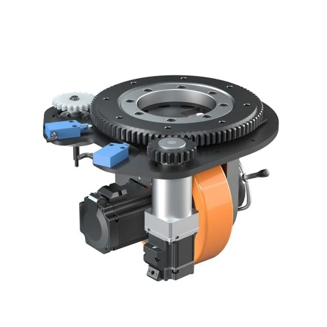
Sizing a drive wheel means resolving one chain of numbers in a fixed order: rated torque, reduction ratio, output torque, maximum torque, rated speed, rated voltage and rated current. The PLT-198 drive wheel makes that chain visible — 9.55 Nm motor-side rated torque, a 32:1 reduction ratio, 260 Nm continuous output torque, 576 Nm maximum torque, 3000 RPM rated speed, 68 A rated current at 48 V rated voltage, and a 1500 kg maximum load. Move any single figure and at least two others move with it.
Why Drive Wheel Sizing Fails When Load Is the Only Input
Payload is the first number most AGV and AMR teams fix, and it is the number that gets compared first. It is also the least useful number on its own. A wheel rated to 1500 kg says nothing about whether it can move that 1500 kg up a grade, stop it within the required distance, hold top speed on a long straight, or survive a duty cycle that never lets the motor cool down.
Three sizing errors account for most of the mismatch between a selected drive wheel and the vehicle it ends up on.
- Peak torque treated as continuous torque. Maximum torque is an intermittent figure with a time limit attached. Treating it as if it were a continuous rating pushes the motor and gearbox into a thermal envelope they were not designed to hold.
- Reduction ratio chosen for torque alone. A 32:1 ratio multiplies torque, but it divides speed by the same factor. High output torque always arrives with a correspondingly low output speed.
- Electrical envelope checked last. Rated current and rated voltage decide which drive amplifier, cabling and battery pack the vehicle can actually carry. These are constraints on the mechanical design, not afterthoughts bolted on at the end.
The practical consequence is that a specification sheet read line by line produces a different answer from a specification sheet read as a chain. The rest of this guide works through the chain and shows where each figure pushes back.
What the AGV Drive Wheel Market Rewards
The commercial context reinforces why the parameter chain matters more than any single headline rating. The global AGV Wheel Drives market was valued at approximately USD 1.2 billion in 2024 and is projected to reach USD 3.5 billion by 2034, growing at a CAGR of 11.5% from 2024 to 2034, according to Reports and Data. The wider Automated Guided Vehicle market is expected to reach USD 5.9 billion by 2025, per Grand View Research, with Asia Pacific holding a 37.6% revenue share in 2025.
Growth is concentrated where duty cycles are hardest. MarketsandMarkets projects the industrial logistics segment for AGVs to grow at a CAGR of 11.6%, and Brandessence Research observes integrated steering drive modules replacing discrete components in order to cut assembly time and maintenance complexity. Both trends push more responsibility onto the drive wheel: one integrated unit now has to carry the load, deliver the torque, hold the speed and satisfy the electrical envelope at the same time.
Regulatory pressure runs alongside that consolidation. ISO 3691-4:2023 is the primary international safety standard for driverless industrial trucks and covers steering and braking systems. EN 1175:2020 specifies electrical and electronic safety requirements for industrial trucks, applicable to drive wheel assemblies. ANSI/ITSDF B56.5 is the specific American safety standard for driverless industrial vehicles, governing performance of drive and steering units. None of these standards names a torque figure, but each one constrains how torque, speed and braking behaviour must be demonstrated.
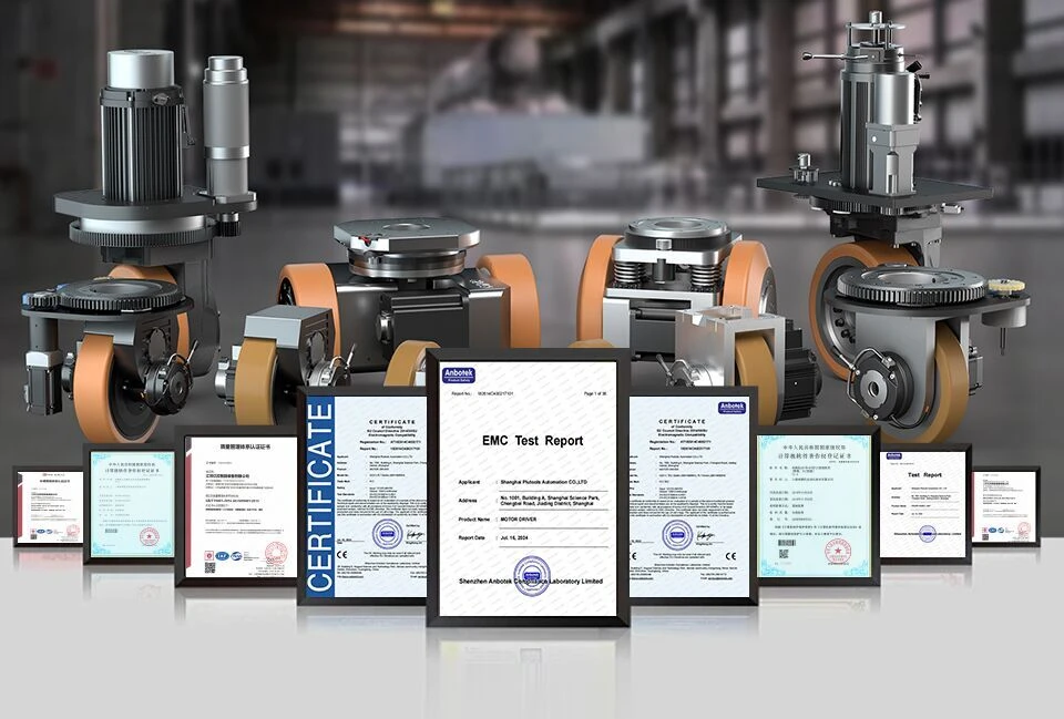
Shanghai Plutools Automation Corporation Co., Ltd. is a national high-tech enterprise headquartered in Shanghai, China, founded in 2017 and specialising in AGV/AMR mobile robots and AGV Drive Wheel units. The company reports more than 22 years of industry R&D and production experience, an R&D team of 60 engineers, over 200 patent technology certifications, a 10,000 square metre manufacturing facility, approximately 100 staff and an annual production capacity of 10,000 units. It exports to the EU, USA, Southeast Asia, South America, the Middle East, Japan and South Korea, with exports accounting for 70% of total sales.
How the Sizing Parameters Constrain Each Other
Each figure in the chain answers a different question, and the order in which they are checked determines whether the result is a workable drive unit or a set of numbers that never quite fit together.
Rated torque: the continuous figure
Rated torque is the torque a motor can deliver indefinitely without exceeding its thermal limits. On PLT-198 that figure is 9.55 Nm, measured at the motor shaft before the gearbox. It is the smallest number in the chain and the one that governs long shifts, continuous towing, and any duty cycle where the vehicle never gets a full cooldown between moves.
Rated torque is also the figure most often skipped in early sizing. Teams calculate the worst-case grade, find a large torque demand, and then match it against maximum torque rather than continuous torque. That passes on paper and fails in service, because the worst case lasts seconds while the shift lasts hours.
Reduction ratio: the exchange rate between speed and torque
A 32:1 reduction ratio multiplies motor torque by 32 and divides motor speed by 32, allowing for losses in the gear train. That single exchange rate is what turns a small, fast motor into a slow, strong drive wheel. On PLT-198, 3000 RPM at the motor becomes roughly 94 RPM at the output shaft, and 9.55 Nm at the motor becomes the 260 Nm published at the output.
The ratio is the parameter most often revisited late in a project. Raise it and the vehicle gains pulling force but loses top speed. Lower it and top speed improves while grade capability falls. Because load and speed are customizable on the PLT series, this trade-off can be tuned to the application instead of being accepted as fixed — a distinction that matters for programmes that expect to run the same platform across several vehicle variants.
Output torque and maximum torque: continuous versus intermittent
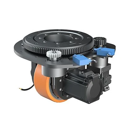
260 Nm is the continuous output figure. 576 Nm is the maximum. The gap between them is headroom, and headroom carries a time limit.
Maximum torque applies to acceleration from rest, grade climbing, ramp transitions and emergency braking — events measured in seconds. Rated torque applies to everything else. A vehicle that climbs a ramp twice per shift needs the maximum figure for those two events and the rated figure for the remaining seven hours. A sizing calculation that checks only 576 Nm against the worst-case grade will pass and overheat.
The practical rule is to size the continuous duty against 260 Nm with margin, and then confirm that the peak events stay inside 576 Nm and inside the thermal recovery the duty cycle allows.
Rated speed and rated current: the electrical envelope
Rated speed of 3000 RPM feeds directly into the speed calculation and indirectly into the power rating. Using the standard relation P = T × n / 9550, 9.55 Nm at 3000 RPM corresponds to roughly a 3 kW continuous motor rating. At the output, 260 Nm at roughly 94 RPM corresponds to approximately 2.55 kW — the difference being losses through the 32:1 gear train. That arithmetic is a fast way to check that a quoted torque and a quoted speed actually belong to the same machine.
Rated current of 68 A at 48 V rated voltage defines the electrical side. It sets the continuous current the drive amplifier must supply, the conductor cross-section in the chassis harness, and the discharge capability the battery pack must provide. A wheel with excellent mechanical numbers but an incompatible current draw forces a redesign of the electrical architecture — usually more expensive than changing the wheel.
Tread and structure: how the load actually reaches the floor
Two mechanical details decide whether a published load rating survives contact with a real floor. Polyurethane tread is widely used on forklift drive wheels because it combines higher load capacity with floor protection in indoor settings, per Mordor Intelligence. On a 1500 kg unit that combination is the whole argument: a harder compound transfers load efficiently but abrades resin floors and generates noise, while a softer compound protects the floor at the cost of rolling resistance and heat build-up.
Carbon steel construction provides the structural rigidity that keeps the load path stable under the torque reversals of forward-reverse duty. It also sets the mass of the unit, which feeds back into the vehicle's own centre-of-gravity calculation — relevant wherever the drive wheel is mounted high or offset from the chassis centreline.
Where the PLT-120 Differential Unit Fits
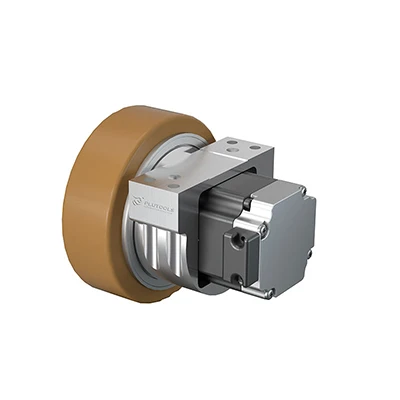
Not every AGV/AMR programme needs a 1500 kg, 260 Nm drive wheel. The PLT-120 differential drive unit covers the light end of the same parameter logic with a 150 kg load rating, IP65 ingress protection, 48 V rated voltage and 11.2 A rated current. The lower current draw is the practical signal: a unit drawing 11.2 A instead of 68 A needs a smaller amplifier and a lighter harness, which is what makes compact AMR chassis viable in the first place.
IP65 matters at this payload band because light AGVs and AMRs are the vehicles most likely to work in mixed environments — retail backrooms, hospital logistics, food and beverage plants, and zones adjacent to wash-down areas. The sizing chain does not change with payload. Establish the payload, convert it into required tractive effort, divide back through the reduction ratio to find motor-side torque, then check the result against continuous ratings rather than peak ratings. Only the magnitudes differ.
Differential drive configurations are also used to achieve tight turning behaviour in smaller logistics bots, which is why the 150 kg class tends to be built around compact differential units rather than heavy single-wheel assemblies.
Step-by-Step: Sizing a Drive Wheel from Payload to Rated Current
- Fix the payload envelope, not the nominal load. Start from the maximum mass the vehicle will ever carry, including attachments and load shift. PLT-198 is specified at a 1500 kg maximum load; PLT-120 at 150 kg. Design against the maximum, then evaluate the continuous case separately.
- Convert payload into required tractive effort. Rolling resistance, grade resistance and acceleration force add together. Whichever of the three is largest usually decides whether rated or maximum torque governs the application.
- Translate tractive effort into wheel torque. Required wheel torque depends on the wheel radius and the total resistance. This is the number to compare against output torque, never against motor torque.
- Step back through the reduction ratio. Divide the required output torque by 32 to find the motor-side demand, then compare it with the 9.55 Nm rated figure. If the continuous demand exceeds 9.55 Nm, the duty cycle needs shortening, the ratio needs raising, or the payload assumption is too optimistic.
- Check speed at the output. A 3000 RPM rated speed through a 32:1 ratio gives roughly 94 RPM at the wheel. Confirm the resulting vehicle speed meets the duty requirement at that output speed — not at motor speed.
- Match the electrical envelope. Confirm the drive amplifier can deliver 68 A continuous at 48 V for PLT-198, or 11.2 A for PLT-120, and that the battery pack and protection scheme support it across the full duty cycle.
- Validate tread, structure and compliance. Confirm the polyurethane tread suits the floor type, that the carbon steel structure suits the mounting arrangement, and that the finished vehicle can be validated against ISO 3691-4, EN 1175 or ANSI/ITSDF B56.5 as the destination market requires.
Use Cases by Payload Band
Heavy-duty towing and automated forklift platforms
At the 1500 kg end, PLT-198 is sized for vehicles where grade climbing and start-stop torque dominate the duty cycle. The 576 Nm maximum torque exists to break away and accelerate a loaded vehicle; the 260 Nm continuous figure covers the run that follows it. Polyurethane tread keeps the load path efficient indoors while protecting the floor, and carbon steel structure holds alignment under repeated torque reversal.
Narrow-aisle and compact AMR chassis
At the 150 kg end, PLT-120 with IP65 protection suits indoor AMR platforms where space is tight, the chassis sits low and dust or wash-down exposure is a genuine risk. The 11.2 A rated current at 48 V keeps the battery pack small enough to fit a low-profile chassis — a constraint that matters as much as torque in this payload band.
Latent lifting and low-profile transfer robots
Where the drive module must sit beneath a load deck, module height and centre of gravity drive the specification more than raw torque. In these builds the sizing question shifts from "how much torque" to "how much torque per millimetre of stack height", and the electrical envelope becomes the deciding constraint.
Mixed fleets sharing one electrical architecture
Programmes running both heavy and light vehicles often standardise on 48 V across the fleet. PLT-198 and PLT-120 both operate at 48 V rated voltage, so one charger strategy and one battery voltage class can serve units drawing 68 A and units drawing 11.2 A. The current rating changes with payload; the voltage class does not. That consistency is what makes a platform strategy practical over several vehicle generations rather than one.
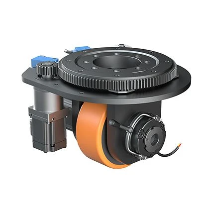
PLT-198 vs PLT-120: Parameter Comparison
The two units sit at opposite ends of the same sizing logic. The comparison below uses only figures that are part of the verified specification for each model.
| Selection parameter | PLT-198 | PLT-120 |
|---|---|---|
| Maximum load | 1500 kg | 150 kg |
| Motor-side rated torque | 9.55 Nm | — |
| Reduction ratio | 32 | — |
| Output torque (continuous) | 260 Nm | — |
| Maximum torque | 576 Nm | — |
| Rated speed | 3000 RPM | — |
| Approximate output speed at rated speed | 94 RPM | — |
| Rated voltage | 48 V | 48 V |
| Rated current | 68 A | 11.2 A |
| Ingress protection | — | IP65 |
| Tread material | Polyurethane | — |
| Structural material | Carbon steel | — |
| Load and speed customisation | Available | Available |
Cells marked "—" are outside the specification set used for this article. Request the current datasheet for those parameters before finalising a low-payload or high-payload design.
Frequently Asked Questions
Does a drive wheel unit need to comply with ISO 3691-4 or EN 1175 for an AGV or AMR project?
The standards apply to the vehicle rather than to the wheel in isolation, but the drive wheel is where their requirements land. ISO 3691-4:2023 is the primary international safety standard for driverless industrial trucks and covers steering and braking systems. EN 1175:2020 specifies electrical and electronic safety requirements for industrial trucks and applies to drive wheel assemblies. For the United States, ANSI/ITSDF B56.5 governs the performance of drive and steering units on driverless industrial vehicles. The destination market determines which of the three governs the validation programme, and the torque, speed and braking figures on the datasheet are the inputs that validation consumes.
Can the load and speed parameters of the PLT-198 be customised, or are they fixed?
Load and speed are customizable on the PLT series, so a 1500 kg / 32:1 / 3000 RPM configuration is a starting point rather than a fixed menu item. Because the parameters form a chain, any change propagates. Raising the load requirement increases the continuous torque demand at the output, which is checked against 260 Nm and, for short events, against 576 Nm. Changing the speed requirement moves the output speed away from the roughly 94 RPM that 3000 RPM through 32:1 produces. Either change should trigger a re-check of the 9.55 Nm motor-side rated torque and the 68 A rated current, since the electrical envelope moves with the mechanical one.
Does a higher torque rating always mean a higher purchase price?
Cost follows the configuration rather than any single rating. Torque, reduction ratio, rated speed, tread compound and structural build are selected together, so two units with the same nominal torque can differ in cost if their ratio or speed requirements differ. The commercially useful approach is to fix the continuous torque and speed requirement first, confirm the electrical envelope, and only then discuss terms. Purchasing terms for the PLT series are a minimum order quantity of 2 units and FOB Shanghai delivery, which keeps the comparison grounded in an actual quotation rather than a headline rating.
How are samples and acceptance handled before a full order?
Acceptance is based on pre-shipment test, and payment terms are 50/50. That structure matters more for drive wheels than for simple components, because a sample validates the whole parameter chain at once: the continuous torque behaviour, the output speed at rated speed, and the current draw at 48 V can all be confirmed against the sizing calculation before production volumes are committed. A sample that only confirms the load rating has confirmed the least informative figure on the sheet.
How should delivery be planned for a customised configuration?
Delivery terms are FOB Shanghai, and scheduling follows the confirmed specification rather than a catalogue part number. Because load and speed are customizable, the specification freeze is the milestone that starts production — so the sizing chain should be closed out early, including the payload envelope, the required output torque, the target output speed and the 48 V current draw. For programmes planning multiple vehicle variants on one platform, sending the full parameter set in a single enquiry shortens the loop considerably. You can send load, speed, voltage and mounting requirements to the Plutools team through plutools.com, or start from the PLT selection manual linked below.
Conclusion
Drive wheel sizing is a chain, not a checklist. Rated torque of 9.55 Nm sets the continuous capability of the motor. The 32:1 reduction ratio converts that into 260 Nm at the output and roughly 94 RPM at the wheel. Maximum torque of 576 Nm covers the seconds-long events — break-away, grade climbing, emergency braking — that the continuous figure was never meant to absorb. Rated speed of 3000 RPM and rated current of 68 A at 48 V define the electrical envelope the chassis must be built around. Polyurethane tread and carbon steel structure decide how that load actually reaches the floor.
The same logic scales down without changing shape. PLT-120 applies it at 150 kg with IP65 protection and an 11.2 A draw at 48 V, which is what allows a lighter amplifier, a lighter harness and a smaller battery pack. Because load and speed are customizable on both units, the selection is tuned to the vehicle rather than accepted as fixed — the difference between buying a component and building a platform that survives several vehicle generations on one electrical architecture.
Next step: size the wheel against your real duty cycle
Send the payload envelope, target speed, battery voltage and mounting constraints, and the Plutools engineering team will work the parameter chain back to a rated torque, ratio and current figure for your AGV or AMR platform.

Download the PLT selection manual (PDF) | Visit plutools.com
Have Questions or Need More Details?
Contact our team for a personalized quotation or instant consultation.
Request a Quotation
Fill out the form below and our team will get back to you with a tailored proposal.
WhatsApp Direct Chat
Prefer to chat in real-time? Message us on WhatsApp for instant assistance & quick answers.
- Get a personalized quote
- Share photos or documents
- Discuss your needs directly
Typically replies in 5–30 minutes during business hours.