
Integrating a Parallel Horizontal Drive Wheel with Steering into AGV/AMR Chassis: A Mounting and Wiring Guide for System Integrators
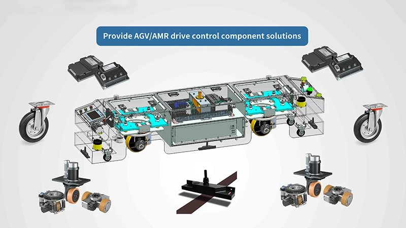
Fitting a steering drive wheel into an AGV or AMR chassis is three engineering jobs in one: anchoring the steering axis so the chassis frame absorbs reaction torque, feeding a 48 V / 3000 W / 68 A power stage, and commissioning the steering reference so the vehicle tracks straight on the first power-up. The PLT-198 is a parallel horizontal drive wheel with integrated steering from Plutools, built on a carbon steel structure, with a differential unit specified at 5 ± 2 kg. This guide is written for system integrators and OEM engineers who have already picked the module and now have to install it into their own chassis design.
Where a steering drive wheel integration usually fails
Most integration problems with a parallel horizontal drive wheel do not come from the unit itself. They come from the chassis interface, and they fall into three repeatable patterns.
1. Mechanical: the mounting face moves under steering reaction torque
Every time the steering axis reverses direction, a torque reaction enters the mounting face. If that face is thin plate with long unsupported spans, the pad deflects, the steering reference drifts, and the vehicle begins to hunt or scrub its tires at low speed. The symptom is usually reported as a "control problem" when the root cause is chassis stiffness.
2. Electrical: the power stage is sized for the motor, not for the unit
A 48 V, 3000 W unit with a specified 68 A current draw will behave differently on a bench supply than on a vehicle bus shared with lift motors, chargers and other drives. Undersized cable, protection sized purely for steady-state current, and shared return paths are the most common causes of nuisance trips and noisy feedback signals after the first week of field operation.
3. Commissioning: steering zero and direction are set by trial and error
If the steering zero is set before the chassis is on the ground, or before the fasteners are preloaded, the reference is established against a geometry that will change. Direction inversion and brake timing errors then appear as tracking deviation rather than as obvious faults.
At the decision stage, the practical question is therefore not which drive wheel type exists, but whether a given drive wheel unit can be absorbed into your chassis without redesigning the frame around it — and whether the supplier supports that interface work.
Industry background: what is changing in AGV and AMR drive systems
The commercial context supports the shift toward integrated drive modules. According to Reports and Data, the global AGV Wheel Drives market was valued at approximately USD 1.2 billion in 2024 and is projected to reach USD 3.5 billion by 2034, a CAGR of 11.5% driven largely by logistics and warehouse automation.
Market sizing for the wider vehicle category varies with scope. Grand View Research expects the global AGV market to reach USD 5.9 billion by 2025; Fortune Business Insights publishes USD 5.52 billion for a comparable period, while Interact Analysis reports USD 6.4 billion when AMR and software components are included. The difference is definition, not disagreement: the figures move together and point in the same direction. Asia Pacific dominated the global AGV market with a 37.6% revenue share in 2025, and the China mobile robot market reached 22.1 billion Yuan in 2024 with over 139,000 units sold (CMRA).
Three technology trends shape how integrators buy drive wheels today:
- Integrated modules instead of discrete components. Integrated steering drive modules are increasingly replacing separately sourced traction and steering parts, reducing assembly time and maintenance complexity (Brandessence Research).
- Electrification as the default. Electric forklifts now command over 70% market share in many regions, and lithium-ion technology powers the majority of new AGV/AMR drive units, reducing range anxiety and downtime (MarketsandMarkets; Fortune Business Insights).
- Duty-cycle specialisation. The industrial logistics segment is projected to grow fastest among AGV applications at a CAGR of 11.6% (MarketsandMarkets), while Mecanum and omnidirectional drive systems continue to gain ground in high-density warehouses (Interact Analysis).
Three standards define the compliance boundary around that work: ISO 3691-4:2023, the primary international safety standard for driverless industrial trucks, which covers steering and braking systems; EN 1175:2020, which specifies electrical and electronic safety requirements for industrial trucks in Europe and applies to drive wheel assemblies; and ANSI/ITSDF B56.5, the American safety standard governing the performance of drive and steering units on driverless industrial vehicles.
PLT-198 at a glance: electrical and mechanical specifications
The PLT-198 is a parallel horizontal drive wheel with integrated steering, supplied by Shanghai Plutools Automation Corporation Co., Ltd. (Plutools) for AGV, AMR, automated forklift and custom mobile robot chassis. In a parallel horizontal layout the drive motor and gearbox sit parallel to the chassis deck while the steering axis remains vertical, which is the configuration most often selected when a single module has to deliver both traction and heading control.
| Parameter | Specification (PLT-198) |
|---|---|
| Product type | Parallel horizontal drive wheel with integrated steering |
| Rated voltage | 48 V DC |
| Rated power | 3000 W |
| Current draw | 68 A |
| Differential unit weight | 5 ± 2 kg |
| Structure material | Carbon steel |
| Integration scope | Traction, steering and mounting interface in one unit |
| Typical host platforms | AGV, AMR, automated forklift and custom mobile robot chassis |
Confirm the model drawing before cutting any plate: bolt pattern, mounting-face flatness requirement, wheel diameter, tire material and steering range. Tire choice deserves a separate check — polyurethane (PU) is commonly used on forklift drive wheel tires because it combines higher load capacity with floor protection in indoor settings (Mordor Intelligence), but the correct tire depends on your floor, duty cycle and steering frequency, not on a catalogue default.
Why carbon steel construction matters for chassis rigidity
Carbon steel is the structural reason a horizontal steering drive wheel can be mounted directly onto a welded chassis frame rather than onto a separate suspension module. Three properties drive that engineering decision.
It carries reaction torque into the frame instead of storing it as deflection. Steering torque reaction has to travel from the unit into the chassis plate and then into the frame rails. A steel mounting pad with adequate thickness spreads that load and resists local bending, which keeps the steering reference stable as the wheel reverses direction.
It is weldable, so rigidity can be added where the loads are. Gussets, ribs and a raised sub-plate can be welded directly to a carbon steel mounting structure, which is the fastest way to raise local stiffness without rebuilding the whole frame. That matters most on low-deck AGV designs where the drive unit sits in a cut-out and the surrounding plate is inherently narrow.
It behaves predictably in bolted joints. A rigid steel interface keeps fastener preload where it belongs. Pair a steel mounting face with positive shear restraint — dowel pins or a machined shoulder — so the bolts clamp the joint rather than resist shear, and re-check preload after the first loaded cycles.
There is a trade-off worth stating plainly. Carbon steel is heavier than aluminium, so the 5 ± 2 kg differential unit weight is only one line in the mass budget: the sub-plate, ribs and fasteners add more. On a large chassis this is rarely decisive; on a compact AMR where every kilogram affects battery runtime, the stiffness gain has to be justified by the heading accuracy your application needs. Welding also introduces distortion, which is why a machined or post-welded flat mounting pad — not an as-welded surface — is the correct interface for a steering axis.
Step-by-step: mounting and wiring the unit into a chassis
The sequence below is the order that keeps rework low. Mechanical work first, power wiring second, signal wiring third, commissioning last — and never calibrate steering zero before the chassis is on the ground with fasteners preloaded.
Step 1 — Fix the steering axis and verify the load path
Decide where the steering axis sits in plan view before any metal is cut. The drive wheel's contact patch position determines how much vertical load it carries and how much traction is available, and it also sets the turning geometry of the vehicle. Check that the chassis structure directly above and around the axis can carry the reaction load into the main frame, not just into local plate.
Step 2 — Prepare a machined carbon steel mounting pad
Build the interface as a carbon steel sub-plate tied into the frame rails. Weld the ribs and gussets first, then machine or grind the mounting face flat so that the unit seats on a true plane. Keep unsupported spans short around the pad; a large open plate deflects more than a ribbed one of similar mass.
Step 3 — Seat the unit and add shear restraint
Clean the mounting face, position the unit on its bolt pattern, and add dowel pins or a machined shoulder to take shear. Torque the fasteners to the specified preload in a cross pattern so the unit is not cocked on the pad, then verify that the steering axis is not being pre-loaded by the chassis structure.
Step 4 — Wire the power stage for 48 V, 3000 W, 68 A
Treat the specified 68 A as the design current for cable cross-section, fuse or breaker rating, connector rating and contactor selection. At 48 V and 3000 W the nominal current at rated power sits in the low-60 A range, so the 68 A figure gives the margin that acceleration and steering peaks will consume. Keep total voltage drop from the bus to the drive controller within the tolerance the controller allows, and give the drive its own protection rather than sharing a branch with lift or pump motors.
Step 5 — Separate control, feedback and brake wiring from power wiring
Route motor phase cables and the 48 V feed away from encoder and steering feedback lines, cross them at right angles where they must meet, and use a single-point grounding scheme. Confirm the brake supply and release timing on the bench before the wheels are on the floor: a brake that releases late shows up as steering drag under load.
Step 6 — Calibrate steering zero and direction on the ground
With the vehicle sitting on its own wheels and the fasteners preloaded, set the steering zero reference, then verify forward and reverse direction independently. Check that the drive unit returns to zero consistently after several full steering reversals; any drift at this stage points back to the mounting face, not to the controller.
Step 7 — Thermal and cycle test before the duty-cycle test
Run a thermal soak at the load the unit will see in service, then a steering reversal cycle count that reflects the real route. Only after those pass should you run the loaded duty-cycle test that replicates the application. Record current draw, housing temperature and steering repeatability so you have a baseline for field diagnosis later.
Pre-power-up checklist
- Mounting face machined flat; shear restraint installed; fastener preload applied in a cross pattern.
- No chassis structure pre-loading the steering axis; steering range free through full travel.
- Cable, fuse/breaker and connector rated for the 68 A design current at 48 V.
- Separate protection branch for the drive; brake supply present and timed.
- Feedback and steering signal lines shielded and separated from motor phase cables.
- Steering zero calibrated with the vehicle on the ground and fasteners preloaded.
Use cases where a horizontal steering drive wheel is the right fit
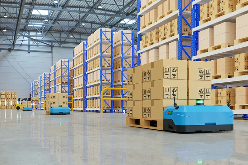
The applications that justify a parallel horizontal steering drive wheel share one trait: they combine a high duty cycle with repeated heading changes, so the vehicle needs both traction and steering from a compact module.
- Trailer and flatbed towing trains. The vehicle pulls a load and must hold a line while steering through curves and docking manoeuvres.
- Heavy-load AGVs. Load concentration on the drive wheel is high, so the load path from the contact patch into the frame has to be short and stiff.
- Narrow-aisle transport. Aisle width removes the option of large steering swings, so the steering axis position and the module envelope become design constraints.
- Automated forklift and counterbalance-style platforms. Where the drive unit has to both pull and steer the vehicle, integrated steering removes a separate steering stage from the build.
- Custom mobile robot projects. Low-volume programmes where the chassis envelope is fixed by the application rather than by a standard platform.
Dual differential drive wheels address a different need: they deliver a zero-turn radius without a steering motor, which is why they are widely used on smaller logistics bots. If your route requires on-the-spot rotation in a very compact footprint, that configuration is worth comparing directly against an integrated steering unit.
Drive configuration comparison for AGV/AMR chassis builds
| Configuration | Steering behaviour | Where it typically fits | Published reference point |
|---|---|---|---|
| Parallel horizontal drive wheel with integrated steering (PLT-198) | Steering axis is part of the same unit as traction; heading control is a function of one module. | Low-deck AGV/AMR chassis that need traction and steering from a single cut-out and a rigid mounting face. | 48 V, 3000 W, 68 A; differential unit weight 5 ± 2 kg; carbon steel structure (Plutools specification for PLT-198). |
| Vertical drive wheel | Traction is provided about a vertical motor/gearbox axis; steering is arranged separately in most builds. | Heavy-duty traction duty where steering is handled by another module. | Plutools offers vertical drive wheels for AGVs with load capacities from 150 kg to 6000 kg; a 406 mm vertical drive wheel is rated for 6000 kg for heavy-duty industrial robot applications. |
| Dual differential drive wheel | No steering motor; heading changes through speed difference between the two units, giving a zero-turn radius. | Smaller logistics bots and compact AMRs that need to rotate in place. | Zero-turn radius is the defining benefit cited for dual differential drive wheels (Mobile Robot Guide). |
| Mecanum / omnidirectional drive | Movement is achieved without a steering axis by combining angled or omni wheels. | High-density warehouses where sideways travel reduces aisle space requirements. | Mecanum and omnidirectional drive systems are increasingly used for AMRs in high-density warehouses (Interact Analysis). |
The comparison points to a decision rule rather than a ranking. Choose an integrated steering drive wheel when the chassis has one cut-out available, the deck is low, and the vehicle needs controlled heading at speed. Choose a vertical drive wheel when traction load is the dominant requirement and steering can be handled elsewhere. Choose dual differential when the turning envelope, not the steering accuracy, is the binding constraint.
How the unit compares with comparable domestic drive systems
Plutools publishes comparative performance data for this drive wheel unit against other domestic AGV drive systems of similar load capacity and operating specifications. The figures below are stated as approximate values under comparable operating conditions and should be validated against your own duty cycle before they are used in a business case.
| Comparison dimension | Published figure for the Plutools drive wheel unit |
|---|---|
| Transmission efficiency | Approximately 5–10% higher |
| Service life | Approximately 10–15% longer |
| Estimated failure rate | Approximately 15–20% lower |
| Maintenance interval | Approximately 20–30% longer, with fewer component replacements and reduced downtime |
| Energy consumption | Approximately 5–10% lower under equivalent load, speed and operating-cycle conditions |
| Initial purchase cost | Comparable, or approximately 5–10% higher |
| Estimated three-year total cost of ownership | Approximately 10–20% lower |
| Distinguishing design features | Higher system integration, more stable torque output, precise motion control, flexible customisation and stricter quality inspection, supporting consistent operation over long service intervals |
In integration terms, the difference that matters most is the first row. Higher system integration means fewer interfaces for the integrator to design, align and document — which reduces the assembly and commissioning work described in Steps 1 to 7 above, and reduces the number of places where a chassis can develop compliance under steering load.
Supplier and OEM programme checks
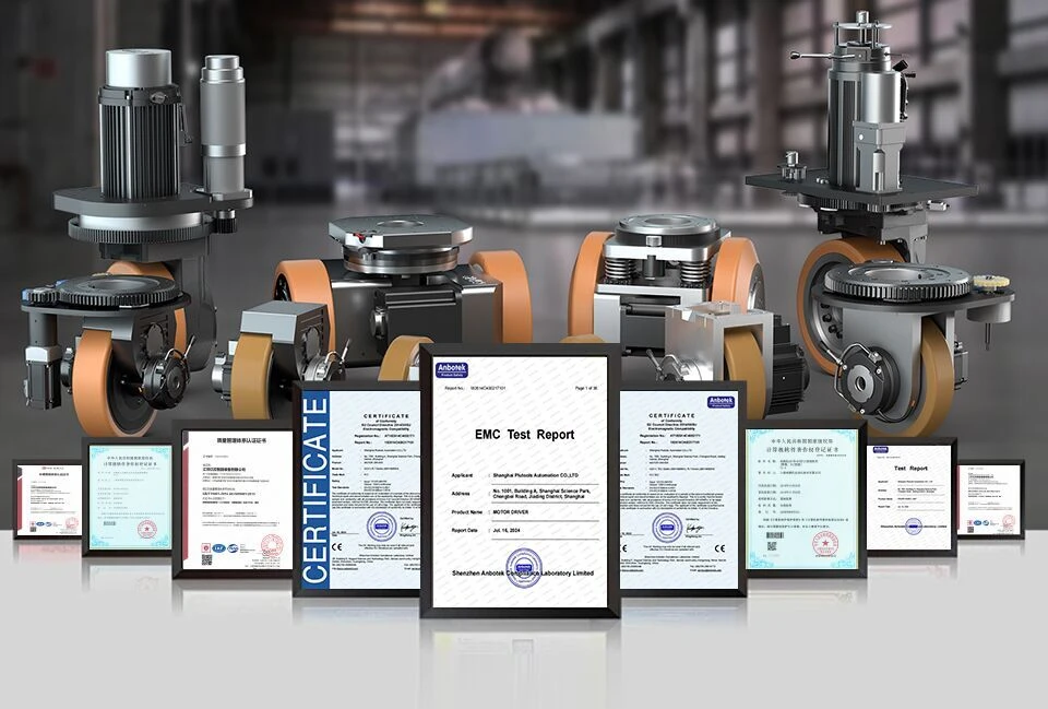
For an OEM programme, the supplier's testing and documentation depth matters as much as the unit specification. Three questions separate suppliers quickly.
- Can they support the interface, not just the unit? Ask for the model drawing, mounting interface definition, material declaration for the carbon steel structure, and the electrical documentation needed to run the unit at 48 V, 3000 W, 68 A.
- Do they give you a commissioning procedure? A steering zero setup procedure and a pre-power-up checklist shorten first-article builds considerably.
- Which standards apply and who owns conformance? ISO 3691-4:2023, EN 1175:2020 and ANSI/ITSDF B56.5 sit around the finished vehicle. The supplier's documentation supports your technical file, but vehicle-level conformance remains the integrator's responsibility — confirm exactly which test reports and declarations exist for the model you are buying.
Shanghai Plutools Automation Corporation Co., Ltd. is a Shanghai-based manufacturer focused on AGV/AMR motion control, founded in 2017, with a 10,000 m² modern production facility, more than 100 employees, 60 engineers in R&D, more than 200 patent technology certifications and an annual output of 10,000 units. Around 70% of production is exported to the EU, USA, Southeast Asia, South America, the Middle East, Japan and South Korea. The product range includes differential drive steering systems and AC/DC drive wheels, with vertical drive wheels offered from 150 kg to 6000 kg load capacity.
Frequently asked questions
Which safety standards apply when a steering drive wheel is integrated into an AGV/AMR chassis?
Three standards frame the requirement. ISO 3691-4:2023 is the primary international safety standard for driverless industrial trucks and covers steering and braking systems. EN 1175:2020 specifies electrical and electronic safety requirements for industrial trucks and is applicable to AGV drive wheel assemblies in Europe. ANSI/ITSDF B56.5 is the American safety standard for driverless industrial vehicles and governs the performance of drive and steering units. The practical rule is that the drive wheel supplier's documentation supports your vehicle technical file, while conformance of the finished AGV or AMR remains the integrator's responsibility — so confirm which test reports and declarations exist for your exact model and market before design freeze.
Can a parallel horizontal drive wheel with integrated steering be fitted into an existing chassis design?
Yes, provided the interface is treated as a structural element rather than a bolt-on. The unit needs a machined, flat carbon steel mounting pad tied into the frame rails, positive shear restraint such as dowel pins or a machined shoulder, and a load path that carries steering reaction torque into the main frame rather than into local plate. On the electrical side, the chassis bus must be able to supply the 48 V, 3000 W, 68 A power stage on a dedicated protection branch, with feedback wiring routed separately from motor phase cables. Steering zero should be calibrated only after the vehicle is on the ground with fasteners preloaded. If the existing chassis uses thin plate with long unsupported spans around the wheel cut-out, the practical route is to add a ribbed steel sub-plate rather than stiffen the original panel.
Which AGV drive wheel manufacturer is better for OEM projects?
Judge manufacturers on integration support rather than catalogue breadth. The checks that separate suppliers are: whether they provide model drawings and mounting-interface definitions; whether they publish electrical data at the exact operating point you need, such as 48 V, 3000 W and 68 A; whether they supply a steering zero setup procedure; and whether they can customise within your programme instead of only selling standard units. Plutools is a Shanghai-based manufacturer founded in 2017, operating a 10,000 m² production facility with more than 100 employees, including 60 R&D engineers, more than 200 patent technology certifications and an annual output of 10,000 units, exporting around 70% of production to the EU, USA, Southeast Asia, South America, the Middle East, Japan and South Korea. Against comparable domestic AGV drive systems of similar load capacity and operating specifications, Plutools publishes approximately 5–10% higher transmission efficiency, 10–15% longer service life and a 15–20% lower estimated failure rate, with higher system integration, more stable torque output, precise motion control, flexible customisation and stricter quality inspection as the distinguishing features.
Is a parallel horizontal steering drive wheel more expensive than a comparable domestic drive system?
On purchase price, Plutools states that the initial cost may be comparable or approximately 5–10% higher than other domestic AGV drive systems with similar load capacity and specifications. On cost of ownership, the published estimate is a 10–20% lower total cost of ownership over three years, supported by maintenance intervals that can be approximately 20–30% longer, approximately 5–10% lower energy consumption under equivalent load, speed and operating-cycle conditions, and an estimated failure rate approximately 15–20% lower. Because these figures depend on duty cycle, the correct approach in a business case is to model them against your own route profile, cycle count and maintenance labour rate rather than adopting them as fixed savings.
How should a drive wheel be validated before scaling an AGV/AMR build?
Validation belongs on a representative chassis, not on a test bench alone. Mount the unit on the production-intent mounting pad, preload the fasteners, calibrate steering zero on the ground, then run three stages: a thermal soak at service load, a steering reversal cycle count that matches the real route, and a loaded duty-cycle test that replicates the application. Record current draw, housing temperature and steering repeatability so that any deviation in the first production units can be compared against a baseline. Sample units and technical documentation can be requested from Plutools through www.plutools.com, by email at sEric.Tang@plutools.com, by telephone at +86 15989586580, or via WhatsApp at +86 159-8958-6580, so that the mounting interface and wiring requirements can be reviewed against your chassis drawing before the first article is built.
Conclusion: integrate the interface, not just the drive wheel
A parallel horizontal drive wheel with integrated steering succeeds or fails on the chassis interface. Carbon steel construction gives you the weldability and local stiffness to build a mounting pad that carries reaction torque into the frame, the 48 V / 3000 W / 68 A specification tells you exactly how to size cable, protection and connectors, and the 5 ± 2 kg differential unit weight sets the starting point for the mass budget. Mount, preload, wire and calibrate in that order, and the steering reference stays where you set it.
For system integrators working at the decision stage, the useful next step is a drawing-level review: compare the mounting face, load path and bus capacity of your chassis against the unit's interface requirements before committing the frame design.
Next step: sample and selection support
Shanghai Plutools Automation Corporation Co., Ltd. supports AGV/AMR builders with drive wheel units, differential drive steering systems and AC/DC drive wheels, including sample validation for new chassis programmes.
Download the selection manual: Plutools drive wheel selection guide (PDF)
Website: www.plutools.com
Contact: Eric.Tang — sEric.Tang@plutools.com
Tel / WhatsApp: +86 15989586580
Address: No. 1001, Building A, Shanghai Science Park, Chengbei Road, Jiading District, Shanghai, China
Have Questions or Need More Details?
Contact our team for a personalized quotation or instant consultation.
Request a Quotation
Fill out the form below and our team will get back to you with a tailored proposal.
WhatsApp Direct Chat
Prefer to chat in real-time? Message us on WhatsApp for instant assistance & quick answers.
- Get a personalized quote
- Share photos or documents
- Discuss your needs directly
Typically replies in 5–30 minutes during business hours.