
What Is a Differential Drive Wheel? A Beginner's Guide for Mobile Robotics Teams
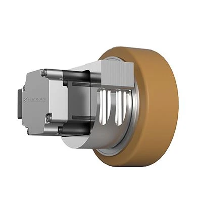
A differential drive wheel is an integrated wheel module — motor, gearbox, wheel and feedback device inside a single housing — that is mounted in pairs on a shared axis so a mobile robot can drive and steer by changing the relative speed of the two wheels. No separate steering motor is required, and no steering linkage is added to the chassis.
That definition answers the question in the title, but it usually triggers a second question in a first design review: if the wheel itself does not steer, how does the robot turn — and how is that different from a parallel horizontal drive wheel? This guide is written for engineers and buyers specifying drive wheels for the first time: graduate mechanical engineers, robotics teams moving from a prototype to a production chassis, and procurement staff who must read a specification sheet before a design freeze.
Throughout the article, one documented product is used as a fixed reference: the PLT-120 Differential Drive Wheel from Plutools. Plutools (Shanghai Plutools Automation Corporation Co., Ltd.) is a Shanghai-based manufacturer of AGV and AMR drive wheel modules founded in 2017, operating a 10,000 m² production facility with more than 100 employees and a main product line focused on drive wheel assemblies for mobile robots. Using a real specification set keeps every number in this explainer traceable to a published fact instead of a rule of thumb.
What Is a Differential Drive Wheel?
A differential drive wheel is a powered wheel assembly that combines a drive motor, a reduction gearbox, the wheel itself and position feedback in one mechanical unit. Its output is rotary motion at the wheel rim, and it is controlled by a motor driver that receives speed, torque or position commands from the vehicle controller.
The word "differential" describes the control principle, not an automotive differential gear. A robot with two such wheels on a common axis steers because the controller commands a different speed to the left wheel and the right wheel. Equal speeds produce straight travel; unequal speeds produce a curved path; opposite speeds rotate the vehicle about its own centre. The heading of the vehicle is therefore a software outcome of two wheel speeds, not a mechanical outcome of a steering actuator.
The PLT-120 is a concrete example of the category. Its published specification lists a rated power of 400 W at a rated voltage of 48 V with a rated current of 11.2 A, a rated speed of 3000 rpm, a drive wheel load of 150 kg, an IP protection level of IP65, a total drive wheel weight of 5±2 kg, carbon steel construction and a PU (polyurethane) wheel tread. In a two-wheel differential pair, a robot uses two of these modules and the chassis carries the rest of its weight on passive wheels.
Why the name causes confusion
Three different product families are routinely listed together in drive wheel catalogues: differential, horizontal and vertical. Only one of them is defined by how the vehicle steers. A differential drive wheel is defined by the steering principle of the vehicle. A horizontal or vertical drive wheel is defined mainly by the orientation of the output axis and by whether the module contains its own steering function. Mixing the two classification systems is the single most common reason a first-time buyer orders the wrong module geometry.
Problem Definition: Why New Robotics Teams Mix Up Differential and Parallel Horizontal Drive Wheels
The confusion is understandable, because the modules look similar in a catalogue photo. A differential drive wheel and a parallel horizontal drive wheel can both be built around a 48 V motor, both can carry a PU tread, both can use a carbon steel housing and both can be shown from the same three-quarter angle. A team comparing pictures rather than mounting drawings will see few differences.
The differences appear at three levels:
- Steering source. A differential module contains no steering axis. Heading change comes from the speed difference between two modules. A parallel horizontal drive wheel with steering contains its own steering function, so a single module can rotate its wheel about a vertical steering axis and the vehicle heading can be changed without a second powered wheel.
- Axis orientation. A vertical drive wheel places the drive axis vertically relative to the mounting plane and is often used where the chassis needs a compact footprint. A horizontal module places the drive axis horizontally and is commonly used where the motor body must sit alongside the wheel rather than above it.
- Chassis consequences. The two choices lead to different mounting plates, different cable exit directions, different maintenance access and different control architectures. These consequences are mechanical and electrical, and they appear long before the robot ever moves.
The practical risk for a beginner is a specification that reads correctly but integrates badly: a module whose mounting dimensions were never checked against the chassis plate, or a steering concept that requires three or four powered wheels where the team assumed two. The rest of this guide therefore separates the steering principle from the module geometry, and shows how a differential pair behaves in a real AGV or AMR build.
Industry Background: Why This Question Appears in Almost Every New Mobile Robot Program
The number of teams asking this question is growing with the market. Reports and Data valued the global AGV wheel drives market at approximately USD 1.2 billion in 2024 and projects it to reach USD 3.5 billion by 2034, a compound annual growth rate of 11.5% from 2024 to 2034, driven largely by logistics and warehouse automation. Grand View Research projects the global automated guided vehicle market to reach USD 5.9 billion by 2025, with Asia Pacific holding a 37.6% revenue share in that year.
Growth at the vehicle level translates directly into growth at the component level. The China Mobile Robot Alliance recorded a China mobile robot market scale of 22.1 billion yuan in 2024, involving more than 139,000 units sold. MarketsandMarkets identifies the industrial logistics segment as the fastest-growing AGV segment, with a projected CAGR of 11.6%, and notes that electric forklifts now command over 70% market share in many regions as a replacement for combustion models.
Two structural trends make the differential-versus-horizontal question more common than it used to be. First, integrated modules are replacing discrete components: Brandessence Research describes integrated steering drive modules replacing separate motors, gearboxes and steering units in order to cut assembly time and maintenance complexity. Second, alternative drive concepts are spreading in parallel — Interact Analysis notes that Mecanum wheels and omnidirectional drive systems are increasingly used for AMRs in high-density warehouses, which means a new engineering team may be comparing several drive principles at once.
Material choice follows the same logic. Mordor Intelligence reports that forklift drive wheel tires commonly use polyurethane (PU) because it provides higher load capacity and better floor protection in indoor settings — which is why a PU tread appears on both differential and horizontal modules, and why the tread alone cannot be used to identify the drive principle.
The PLT-120 as a Reference: What the Published Specifications Actually Say
Reading a differential drive wheel datasheet is easier when the numbers are grouped by function. The table below reproduces the published PLT-120 specification without modification.
| Parameter | Published value (PLT-120) |
|---|---|
| Product type | Differential Drive Wheel |
| Rated power | 400 W |
| Rated voltage | 48 V |
| Rated current | 11.2 A |
| Rated speed | 3000 rpm |
| Rated torque | 1.28 Nm |
| Transmission ratio | 9, 20 (I) |
| Rated output torque | 10, 21 Nm |
| Maximum acceleration and braking torque | 20, 42 Nm |
| Drive wheel load | 150 kg |
| Total drive wheel weight | 5±2 kg |
| IP protection level | IP65 |
| Material | Carbon steel |
| Wheel tread | PU (polyurethane) |
Motor and bus numbers
The 400 W rating at 48 V and 11.2 A places the PLT-120 in the same electrical family as the majority of industrial AGV and AMR platforms, which use a 48 V DC bus. That matters for beginners because it means the module can share a bus with other 48 V devices instead of requiring a dedicated power stage. Rated speed of 3000 rpm is the motor-side figure; the speed actually delivered at the wheel rim depends on the transmission ratio, which is why the ratio must always be read together with the rated speed rather than in isolation.
Torque chain: from motor torque to wheel torque
The rated torque of 1.28 Nm is measured at the motor. The transmission ratio of 9, 20 then multiplies that value to produce a rated output torque of 10, 21 Nm at the wheel, and the maximum acceleration and braking torque of 20, 42 Nm defines the transient envelope available during starts, stops and emergency deceleration. For a first-time buyer, the wheel-level output torque is the number that decides whether the module can start a loaded vehicle on the actual floor surface without slipping, and the maximum torque is the number that decides how quickly the vehicle can stop.
Load, weight and structure
The published drive wheel load is 150 kg per wheel, and the total drive wheel weight is 5±2 kg. The load figure describes what one module is rated to carry, not what a vehicle can weigh. Vehicle payload depends on how many wheels share the load, where the centre of gravity sits, how the load moves during acceleration and braking, and what the floor surface can support. A two-wheel differential robot carries part of its weight on the drive pair and the remainder on passive wheels, so the rated load of the drive pair is only one input into the payload calculation.
IP65, carbon steel and PU tread
IP65 is a stated protection level for the PLT-120. Under the IP code system, the first digit indicates protection against solid objects and dust, and the second digit indicates protection against water — in this case protection against dust ingress and against water projected by a nozzle. That makes the module relevant to industrial environments where dust, cleaning and occasional splashes are present, and it is a different question from chemical resistance or cleanroom compatibility.
Carbon steel is the housing material, which gives the module the structural rigidity expected of an industrial drive unit. The PU wheel tread is specified for low noise and high wear resistance, which is consistent with the wider industry practice of using polyurethane on indoor industrial wheels where floor protection and load capacity both matter.
Practical note: IP65 describes the module's own protection level. Machine-level conformity for an AGV or AMR is a separate matter, because the completed vehicle — not the wheel — is what must be assessed against the applicable safety framework. Section on compliance below explains which standards are relevant and what a buyer should request.
How Two-Wheel Differential Steering Works: Step-by-Step
The best way for a new team to understand a differential drive wheel is to follow the sequence of a simple two-wheel robot build.
- Mount the pair on a common axis. Two PLT-120 modules are installed so that their wheel centres lie on one line, normally through the centre of the chassis. The mounting dimensions, bolt pattern and cable exit of each module must be checked against the chassis drawing before any plate is machined.
- Give each wheel its own driver channel. Each module receives independent commands from the motor driver. This independence is the mechanism that makes steering possible, and it is the reason a differential pair cannot be wired to a single shared drive channel.
- Command equal speeds for straight travel. When both modules are commanded to the same speed, the robot travels forward or backward in a straight line. Small mechanical differences between the two units are corrected by the controller rather than by a mechanical linkage.
- Command different speeds for a curve. When the left and right wheels run at different speeds, the robot follows a curved path. The radius of that curve is set by the speed difference, and the curvature can be changed continuously without any steering actuator moving.
- Command opposite directions for rotation. When one wheel runs forward and the other runs backward, the vehicle rotates about its own centre. This zero-turn radius behaviour is a widely recognised characteristic of dual differential drive wheels and is one of the main reasons the configuration is used on smaller logistics robots, especially where aisle space is limited.
- Close the loop with feedback. Speed and position feedback allow the controller to hold the commanded motion, which is what turns a pair of motorised wheels into a vehicle that can follow a route. Both differential and steering drive systems depend on this feedback loop for accurate positioning.
- Design the braking envelope. Braking torque is a published figure on the module — 20, 42 Nm maximum acceleration and braking torque on the PLT-120 — and the stopping distance of the vehicle has to be calculated from that envelope together with vehicle mass, floor friction and load state.
One structural point is often missed by first-time builders: in a two-wheel differential chassis, the drive pair typically does not carry the whole vehicle. The remaining weight is supported by casters or fixed wheels, which means the floor contact pattern and the load distribution determine how much traction the drive pair can generate. The module rating is a constraint, not a guarantee.
Differential Versus Parallel Horizontal Drive Wheel: A Side-by-Side Table
The comparison below is limited to published specification values, so that a beginner can see exactly which differences are documented and which conclusions belong to the application.
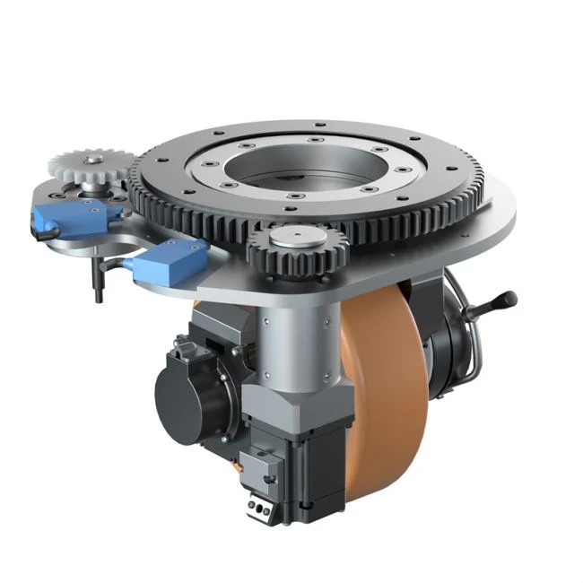
| Attribute | PLT-120 Differential Drive Wheel | PLT-220 Parallel Horizontal Drive Wheel with Steering |
|---|---|---|
| Steering source | Speed difference between two wheels | Integrated steering function in the module |
| Wheels needed for heading control | Two powered modules on a shared axis | A single steering module can change heading |
| Rated voltage | 48 V | 48 V |
| Rated power | 400 W | 750 W |
| Rated current | 11.2 A | 18 A |
| Rated speed | 3000 rpm | 3000 rpm |
| Rated torque | 1.28 Nm | 2.4 Nm |
| Reduction ratio | 9, 20 | 28 |
| Output torque | 10, 21 Nm | 58 Nm |
| Max torque | 20, 42 Nm (acceleration and braking) | 174 Nm |
| Max load | 150 kg (per drive wheel) | 1000 kg |
| Material | Carbon steel | Carbon steel |
| Wheel tread | PU | PU |
Reading the table correctly requires attention to two things. First, the PLT-120 column describes a module used in a pair, so its 150 kg is a per-wheel figure that combines with the second wheel and with passive support; the PLT-220 figure describes a heavier module with an integrated steering function. Second, the higher torque and load numbers in the parallel horizontal column do not make the differential module inferior — they describe a different job. Differential modules suit vehicles that turn in tight spaces and benefit from a simple, low-component-count drivetrain; horizontal modules with steering suit vehicles that need a large single-module capacity or a steering behaviour that a differential pair cannot produce.
The same distinction continues across the wider Plutools family. The PLT-198 Planetary Horizontal Drive Wheel with Steering is specified at 48 V, 3000 W, 68 A, a reduction ratio of 32, an output torque of 260 Nm and a maximum load of 1500 kg, while the PLT-210 parallel horizontal drive wheel with steering is specified at 48 V, 3000 W, 68 A, a reduction ratio of 32, an output torque of 260 Nm and a maximum load of 1200 kg. What these modules share with the PLT-120 is the integrated-module idea and the 48 V bus; what separates them is whether steering lives inside the module or in the control of two wheels.
Where Differential Drive Wheels Fit: Scenario and Project Fit
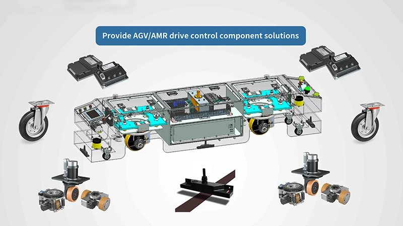
Differential drive wheels are used in intelligent logistics, industrial automation, warehousing, automotive manufacturing, electronics manufacturing, food and beverage production, pharmaceutical manufacturing, e-commerce fulfilment centres, airport logistics and port transportation. In each of these settings the drive wheel performs the same core functions: it provides driving, steering, braking and load-bearing capability for the mobile platform, converts motor power into vehicle movement, and — together with the motor, gearbox, wheel, encoder and braking system — improves motion accuracy, structural integration and equipment reliability while reducing installation space inside the chassis.
Working conditions to design against
Typical operating environments are indoor factories, automated warehouses, production workshops, logistics centres and semi-outdoor industrial areas. The drive wheel usually operates continuously or intermittently, with frequent starting and stopping, forward and reverse movement, narrow aisles, heavy loads, dust, vibration and temperature variation. Floors may be concrete, epoxy, steel or slightly uneven, and each surface changes the traction available to a PU tread. For projects with unusual conditions, special versions can be engineered — low-temperature warehouses, high-humidity areas, cleanrooms, dusty workshops and heavy-duty industrial applications are all recognised requirement categories, and the reference library includes low-temperature and explosion-proof drive wheel design directions.
How the drive wheel operates in a project
Operation may be continuous or task-based. The module can be used in single-wheel drive, dual-wheel differential drive, steering drive or multi-wheel coordinated drive modes, with the vehicle control system issuing speed, torque and position commands through the motor driver. Combined with encoders and a servo drive, the wheel supports precise acceleration, deceleration, steering and positioning for automatic route following, task dispatching, obstacle avoidance, automatic charging and 24/7 unmanned operation.
Equipment the drive wheel is matched with
Differential and other drive wheel modules are commonly integrated with AGVs, AMRs, automated forklifts, transfer robots, inspection robots, cleaning robots and other mobile platforms. The supporting ecosystem includes servo motors, motor drivers, encoders, electromagnetic brakes, steering mechanisms, PLCs, vehicle controllers, batteries, battery management systems, safety laser scanners, cameras, LiDAR sensors, magnetic navigation sensors and fleet management software. Modules are also combined with conveyors, robotic arms, lifting platforms, roller tables, automatic charging stations and warehouse management systems to build a complete intelligent logistics solution.
A project example
In one documented project, an AGV manufacturer and industrial automation system integrator in Brazil integrated 200 drive wheel units into an ultra-heavy-duty AGV with multiple navigation modes. The project ran for two years, providing drive, differential steering and precise motion control. Reported results were stable operation under heavy-load conditions, accurate route tracking, flexible steering and reliable material transportation, with the highlight being high load capacity, high output torque, precise differential control, multiple navigation compatibility and customised system integration. For a beginner, the relevant lesson is not the unit count but the scope: differential steering was selected because the vehicle needed flexible heading control combined with heavy payloads, and the drive modules were customised to the chassis rather than the chassis being adapted to a catalogue part.
What to Check Before You Commit a Differential Drive Wheel to a Chassis
The following checklist converts the explanation above into decisions that must be closed before a chassis drawing is frozen.
- Steering concept first. Decide whether heading is produced by two driven wheels or by a module with an integrated steering function. Everything else — mounting plate, cable routing, controller channel count — follows from this decision.
- Load per wheel, not payload. Compare the vehicle's actual load share per drive wheel against the published drive wheel load, taking centre of gravity and dynamic transfer into account.
- Torque against the real floor. Check rated output torque against the rolling and gradient resistance of the intended route, and check maximum acceleration and braking torque against the stopping requirement.
- Voltage and bus compatibility. Confirm that the module voltage and current match the battery and driver architecture of the vehicle.
- Environmental protection level. Match the stated IP protection level to the actual environment: dust, cleaning methods, humidity and temperature range are project inputs, not defaults.
- Mounting dimensions and weight. Verify mounting dimensions, wheel diameter and module weight against the chassis design and the suspension or caster arrangement.
- Feedback and braking requirements. Specify encoder type, communication protocol and braking method at the same time as the mechanical interface, because these choices affect both wiring and control software.
- Customisation scope. Confirm early whether the project needs standard units or customised load capacity, wheel diameter, motor power, voltage, rated speed, reduction ratio, mounting dimensions, encoder type, brake system, connector, cable length, logo or packaging.
For projects that need a modified module, a manufacturer with an established customisation process removes a large part of the integration risk. Plutools operates as a factory offering OEM, ODM, custom manufacturing, sample development and production runs from small to large batches, with a published monthly capacity of 12,000 units, a minimum order quantity of 2 units, 100% testing and a lead time of 30–45 days. Customisation options cover load capacity, wheel diameter, motor power, voltage, rated speed, reduction ratio, mounting dimensions, encoder type, brake system, connector, cable length, logo and packaging, and the company's export markets include the EU, the US, the Middle East and Southeast Asia. Product information is available at plutools.com.
FAQ: Differential Drive Wheels for First-Time AGV and AMR Teams
Is the PLT-120 differential drive wheel compliant with AGV safety and protection requirements?
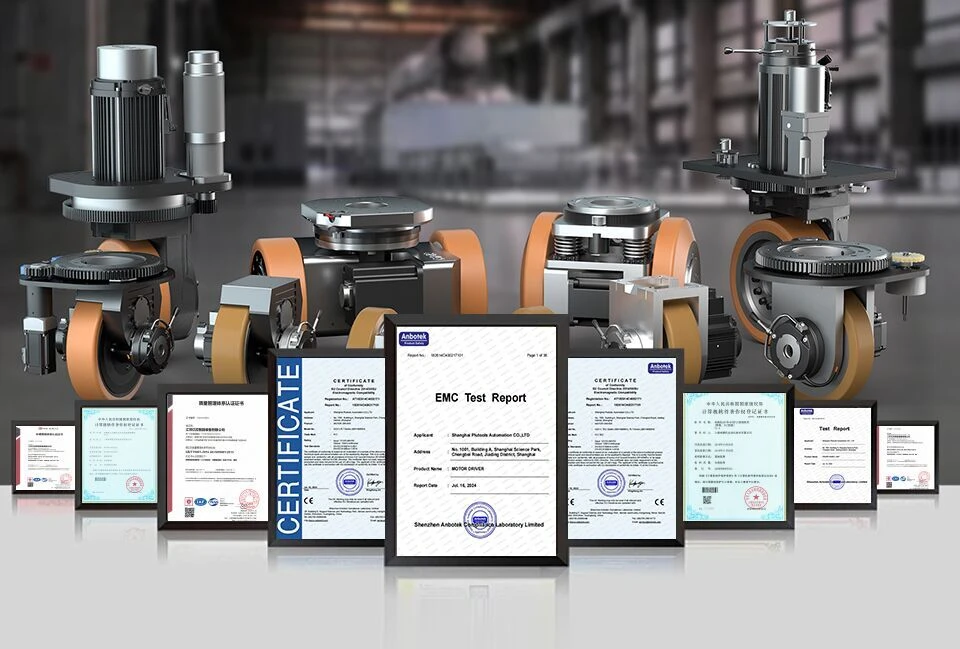
The published PLT-120 specification states an IP protection level of IP65, which means protection against dust ingress and against water projected by a nozzle. Machine-level safety is a separate question. ISO 3691-4:2023 is the primary international safety standard for driverless industrial trucks and covers steering and braking systems; EN 1175:2020 specifies electrical and electronic safety requirements for industrial trucks in Europe and is applicable to AGV drive wheel assemblies; and ANSI/ITSDF B56.5 is the specific American safety standard for driverless industrial vehicles, governing the performance of drive and steering units. Because these standards apply to the completed vehicle rather than to the wheel alone, a buyer should request the drive wheel specification sheet and the applicable documents for the destination market, and confirm how the finished AGV or AMR will be assessed. Keep in mind that IP65 describes the module's own protection, not a vehicle-level conformity statement.
What can one PLT-120 carry, and how does it behave in a two-wheel differential pair?
The PLT-120 is published with a drive wheel load of 150 kg, a rated power of 400 W at 48 V and 11.2 A, a rated speed of 3000 rpm, a rated torque of 1.28 Nm, a rated output torque of 10, 21 Nm, a maximum acceleration and braking torque of 20, 42 Nm and a total drive wheel weight of 5±2 kg. In a differential pair, the two modules are commanded independently, so the vehicle steers by speed difference and can rotate about its own centre when the wheels are commanded in opposite directions. The 150 kg figure is per wheel and is not the vehicle payload: payload depends on how the total weight is distributed between the drive pair and the passive wheels, on the floor surface, and on the acceleration and braking profile of the application.
What drives the cost of a differential drive wheel project?
Plutools does not publish a list price for the PLT-120, so budgeting starts from configuration and volume rather than from a catalogue number. The variables that change the commercial picture are the same ones that change the design: load capacity, wheel diameter, motor power, voltage, rated speed, reduction ratio, mounting dimensions, encoder type, brake system, connector, cable length, logo and packaging, together with order quantity and delivery schedule. The published commercial frame is a minimum order quantity of 2 units, a monthly capacity of 12,000 units and a lead time of 30–45 days. For a project budget, the practical approach is to define the required configuration first, then request a quotation against that configuration so that the comparison between suppliers is made on identical specifications.
Can we validate a differential drive wheel with a sample before committing to a chassis design?
Sample validation is the normal route for first-time builds. Plutools supports sample development as part of its factory operation, with production runs from small to large batches, a minimum order quantity of 2 units and 100% testing, so a development team can obtain units for bench and floor testing before the chassis design is frozen. Remote technical support is available during integration. For a new mobile robotics team, the useful sequence is: confirm the steering concept and load share, request a sample or sample pair against the intended configuration, validate traction, stopping and positioning behaviour on the actual floor, then release the chassis drawing. To start a sample request or an engineering discussion, contact Eric.Tang at sEric.Tang@plutools.com, by telephone or WhatsApp at +86 15989586580, or through the WhatsApp link on the Plutools website.
What is the lead time for differential drive wheels?
The published lead time for Plutools drive wheels is 30–45 days, supported by a monthly capacity of 12,000 units and 100% testing before shipment. For planning purposes, the lead time should be placed alongside the rest of the integration sequence rather than treated as a standalone number: specification and sample validation come first, chassis design and controller commissioning follow, and volume production units are then scheduled against the build plan. Teams that begin the sample conversation early generally avoid the situation where the drivetrain becomes the critical path of the project. A full specification and selection manual is available for download here: PLT Drive Wheel Selection Manual 2026.
Conclusion: One Definition, Two Decisions
A differential drive wheel is an integrated, self-contained powered wheel module that delivers drive, braking and load-bearing capability, and that produces vehicle steering through the speed difference between two modules mounted on a shared axis. It does not contain a steering actuator, and it should not be confused with a parallel horizontal drive wheel, which carries its own steering function and changes heading through the module rather than through a pair. The PLT-120 illustrates the differential category with a published specification of 400 W at 48 V, 11.2 A, 3000 rpm, a 150 kg drive wheel load, a 5±2 kg module weight, IP65 protection, carbon steel construction and a PU wheel tread.
For a mobile robotics team at the research and evaluation stage, that definition leads to two decisions: whether heading should come from two driven wheels or from a steering module, and whether the selected module fits the actual load, floor, environment and control architecture of the vehicle. Answering those two questions before drawing the chassis plate is what separates a clean first integration from an expensive redesign.
Next Step: Validate the Module on Your Own Floor
Plutools supplies AGV, AMR and forklift drive wheel modules as a factory, with OEM, ODM and custom manufacturing, a minimum order quantity of 2 units, 100% testing and a 30–45 day lead time. If you are specifying a differential drive wheel for a new chassis, start with a sample pair and a specification review.
Contact: Eric.Tang | Email: sEric.Tang@plutools.com | Tel / WhatsApp: +86 15989586580
Website: www.plutools.com | Download the PLT Drive Wheel Selection Manual 2026
Have Questions or Need More Details?
Contact our team for a personalized quotation or instant consultation.
Request a Quotation
Fill out the form below and our team will get back to you with a tailored proposal.
WhatsApp Direct Chat
Prefer to chat in real-time? Message us on WhatsApp for instant assistance & quick answers.
- Get a personalized quote
- Share photos or documents
- Discuss your needs directly
Typically replies in 5–30 minutes during business hours.