
Solving Impact and Stiffness Challenges in Robotics with LFT Carbon Fiber Composite Plastic
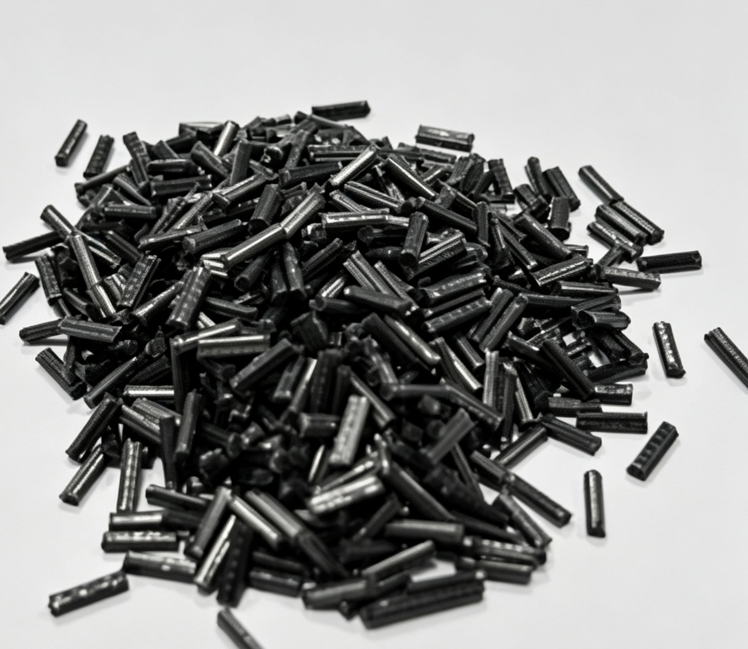
LFT carbon fiber composite plastic — long-fiber reinforced thermoplastic compound developed for robotics structural parts that must absorb impact without giving up rigidity.
Robotics structural parts rarely fail because the material is too weak. They fail because the material was chosen for stiffness and then asked to absorb impact it was never designed to take. LFT carbon fiber composite plastic is a long-fiber reinforced thermoplastic compound built to close that gap. One documented LFT carbon fiber grade reaches 350 MPa tensile strength (ISO 527-2), 510 MPa flexural strength and 30,700 MPa flexural modulus (ISO 178), 40 kJ/m² Izod impact (GB/T 1843) and 7.8% elongation at break at a density of 1.28 g/cm³ — a combination that lets a single injection-molded part carry structural load and still survive the impact events that robotics hardware actually experiences.
Why Impact and Stiffness Pull in Opposite Directions
Stiffness and impact resistance are governed by different physical mechanisms inside a fiber-reinforced part, and optimizing one usually damages the other unless the reinforcement architecture is designed for both from the start.
Stiffness in a fiber-reinforced thermoplastic comes from the load path created by the reinforcement. Longer fibers, higher fiber content and better fiber orientation along the load axis all raise flexural modulus. Impact resistance comes from energy dissipation — plastic deformation of the polymer matrix, controlled fiber pull-out, and interface failure that consumes energy before a crack propagates. That dissipation depends on having enough continuous reinforcement length for fibers to be pulled out of the matrix rather than simply sheared off at their ends.
This is where conventional short-fiber compounds run into trouble. In ordinary short fiber reinforced thermoplastics, fiber length is typically below 12 mm. When a short-fiber part is injection molded, the fibers are further shortened by the screw and the gate, and the remaining length provides limited pull-out distance. The result is a part that behaves predictably in stiffness but has little reserve when a robot arm takes a sudden load, when a gripper collides with a fixture, or when a mobile platform drives over an obstruction.
The failure signatures are consistent and easy to recognize in the field:
- Hairline cracking at sharp corners, boss roots and rib intersections after repeated impact cycles
- Bolt-hole elongation and loss of clamp load on joint interfaces
- Progressive drift in repeat positioning accuracy that cannot be corrected by recalibration
- Delamination-type separation in parts that were originally specified as laminate or thermoset
Design engineers often respond by adding wall thickness. That restores stiffness on paper but adds mass at the worst possible location — the moving end of a kinematic chain — which raises inertia, increases motor and reducer load, and lowers the achievable acceleration the whole robot was specified to deliver.
Where the Requirement Comes From: Industry Background
The pressure to resolve impact and stiffness simultaneously is not isolated to one robotics category. It is being driven by several hardware sectors at once — industrial robotics, collaborative robots, mobile and logistics robots, and the low-altitude economy equipment segment that includes unmanned aircraft and their ground support systems.
Carbon fiber reinforced plastic is a large and still expanding material category. Verified third-party market research places the global market at USD 23.8 billion in 2026, projected to reach USD 43.7 billion by 2033. Within that market, the automotive application segment accounted for the largest application share at 34.7% of revenue in 2025, reflecting how strongly transport and mobility hardware now drive composite adoption.
Two structural forces sit behind those figures for robotics buyers specifically.
The first is mass location, not mass total. In a serial robot arm, mass near the base is nearly free; mass at the wrist is expensive because every kilogram at the end effector must be accelerated and decelerated by the joint and carried by the reducer. A material that lets a link or gripper body be 42% lighter than the aluminum equivalent — a result documented in the Polygram power battery pack housing project — changes the dynamic specification of the machine, not just its bill of materials.
The second is the shift from static load cases to abuse load cases. Collaborative robots are designed to operate near people, which means contact events are expected rather than exceptional. Mobile robots operate on uneven floors and ramps. Low-altitude equipment must tolerate hard landings and ground handling. These are energy-absorption requirements, and they are the exact requirement that a stiffness-first material selection tends to ignore.
What LFT Carbon Fiber Composite Plastic Is and What It Delivers
LFT stands for long fiber reinforced thermoplastic. In the LFT process, reinforcement fibers are impregnated with resin through a dedicated die system to produce fully impregnated long strands, which are then cut to the length required. The resulting compound carries fiber lengths in the 5–25 mm range, compared with the below-12 mm fibers typical of ordinary short fiber reinforced thermoplastics. Parts are produced by injection molding, extrusion or compression molding depending on the end use.
The base resin is selected to match the thermal, chemical and processing environment of the part. The most widely used base is polypropylene (PP), followed by PA6, PA66, PPA, PA12, MXD6, PBT, PET, TPU, PPS, LCP and PEEK. Reinforcement is most commonly glass fiber or carbon fiber, with special fibers such as basalt and quartz available for specific requirements. Carbon fiber content in LFT grades is typically specified in the 20–60% range, and the finished compound can be used for injection molding, extrusion or molding, or as a direct replacement for steel and thermoset parts.
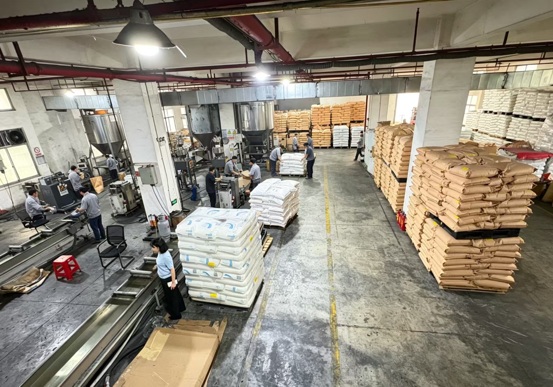
Material formulation and staging: LFT grades are specified by resin system, fiber type and fiber loading before any tooling is released.
Documented mechanical and physical values
The table below lists the property values associated with the LFT carbon fiber composite plastic product family. Values are company-reported parameter data tied to the named test standards.
| Property | Value | Test standard / basis |
|---|---|---|
| Tensile strength | 350 MPa | ISO 527-2 |
| Flexural strength | 510 MPa | ISO 178 |
| Flexural modulus | 30,700 MPa | ISO 178 |
| Izod impact | 40 kJ/m² | GB/T 1843 |
| Elongation at break | 7.8% | Product parameter data |
| Density | 1.28 g/cm³ | Product parameter data |
| Fiber content | 20–60% long carbon fiber | Product specification range |
| Fiber length in compound | 5–25 mm | LFT process specification |
The manufacturing entity behind the material
Polygram is the brand of Guangdong Baolijin New Material Technology Co., Ltd, a high-tech enterprise based in Huangjiang Town, Dongguan City, Guangdong Province, China, specializing in the research, development, production and sale of thermoplastic long-fiber (LFT) carbon fiber composites, conductive and antistatic plastics, and graphene thermally conductive plastics. The company was established in 2017, operates a 4,000 m² facility with 30 employees and a 10-engineer R&D team, and exports approximately 30% of its output to Europe, America and Southeast Asia.
What matters for a robotics program is the service model rather than the headcount. Polygram runs an ODM model that covers material design, mold development and injection molding as one continuous process, which is the sequence that determines whether a long-fiber part actually retains its fiber length at the point where impact resistance is needed.
Step-by-Step Breakdown: Engineering a Part That Is Both Stiff and Tough
Choosing LFT carbon fiber composite plastic does not automatically produce an impact-tolerant stiff part. The balance is achieved through a sequence of decisions, and each step constrains the next. The sequence below reflects the working order used in ODM projects where material design, tooling and molding are handled together.
Step 1 — Define the impact event, not only the static load
Start with what actually hits the part. A robot joint link sees transient torque overload during emergency stops. A gripper body sees direct contact with workpieces and fixtures. A mobile robot chassis sees repeated low-energy impacts from floor transitions. Record the expected impact energy, the impact location, the temperature at that location, and how many cycles the part must survive. Without this, the material specification has no target.
Step 2 — Set the stiffness floor from the accuracy requirement
Work backward from allowable deflection. If the part is a link, the permissible deflection at the tool center point defines the minimum flexural modulus for the chosen geometry. The 30,700 MPa flexural modulus of LFT carbon fiber composite plastic is the reference value used to size wall sections at this stage.
Step 3 — Fix fiber length before fiber content
Buyers often reach for higher fiber loading first. Length matters more for impact. A 20–60% loading range is available, but if the processing route shortens 5–25 mm fibers down to short-fiber lengths at the gate, higher loading will raise modulus while leaving impact performance flat. The fiber length that survives to the molded part is the number that governs toughness.
Step 4 — Choose the resin system around temperature and chemistry
PP is the most common LFT base for cost-driven parts. PA6, PA66, PPA, PA12, MXD6, PBT, PET, TPU, PPS, LCP and PEEK extend the envelope for higher temperature, chemical exposure or dimensional stability requirements. A battery pack housing, for example, must resist electrolyte exposure as well as mechanical shock, which is why the documented power battery project specified a resin system validated against electrolyte resistance rather than a generic grade.
Step 5 — Control fiber orientation through flow design
Long-fiber parts are anisotropic. Fibers align with the flow front, so gate position, runner design and wall thickness transitions decide where the part is stiff and where it is not. Ribs that run counter to the principal load path will not deliver the modulus the material is capable of. This is a simulation and tool-design task, not a material data sheet task.
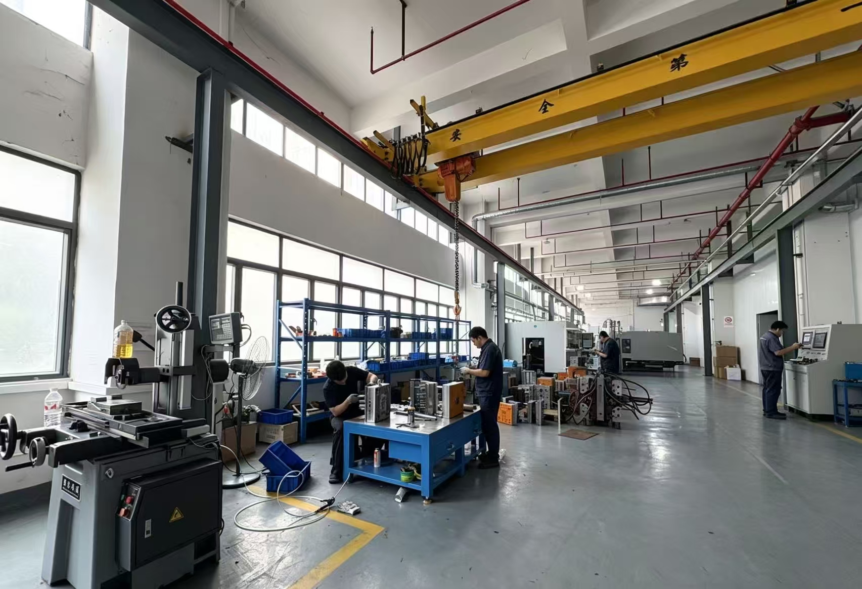
Tool development: gate and runner geometry determine fiber orientation and therefore the stiffness distribution in the finished part.
Step 6 — Build the tool alongside the material
Long-fiber compounds require flow channels and gate designs that avoid unnecessary fiber breakage. Because Polygram operates mold development in-house as part of the ODM scope, the tool can be designed against the specific compound rather than adapted from a short-fiber tool after the fact.
Step 7 — Mold with process control, then inspect 100%
Injection parameters — barrel temperature profile, screw speed, back pressure, injection velocity — all influence fiber attrition. Once a process window is established, it must be locked. Polygram applies 100% testing to production output, which is the mechanism that detects process drift before it reaches assembly.
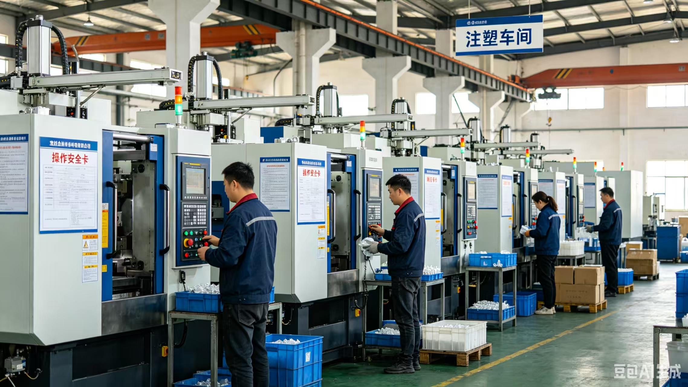
Injection molding: locked process parameters protect the fiber length that provides impact resistance in the finished component.
Step 8 — Validate against the named standards
Verification should reference the same standards used in the specification: ISO 527-2 for tensile properties, ISO 178 for flexural properties, and GB/T 1843 for Izod impact. Requesting results against these methods — rather than accepting an unlabeled headline number — is the minimum discipline for a robotics structural release.
Top 5 Robotics Applications Where the Balance Matters Most
Not every part in a robot benefits equally from long-fiber reinforcement. The five applications below are the ones where impact and stiffness demands most often collide, and where the material's documented property set has the clearest decision value.
1. Joint links and arm segments
These parts set the dynamic performance of the whole machine. They need flexural modulus high enough to hold deflection under payload, and impact resistance high enough to survive emergency-stop torque transients. Mass here is multiplied by acceleration in every cycle, so density of 1.28 g/cm³ directly converts into lower inertia and reduced reducer load.
2. End effectors and gripper bodies
A gripper is the component most likely to make unintended contact. Stiffness determines repeatability of the grasp position; impact resistance determines whether a collision ends with a scuff or a cracked housing. This is the application where the 40 kJ/m² Izod impact value is most directly relevant.
3. Mobile robot chassis and protective housings
Mobile platforms accumulate low-energy impacts continuously — floor transitions, dockings, curb strikes. The structural frame needs rigidity for sensor alignment and impact tolerance for the cumulative damage. Long fiber provides both without adding the mass that would reduce battery runtime.
4. Reducer housings and mounting flanges
Housings carry bearing loads and must hold bore alignment. Stiffness is critical for gear mesh quality; impact resistance matters because a shock load transmitted through the output flange will find the weakest section of the housing. Long-fiber compounds allow integrated features that would require separate assemblies in metal.
5. Low-altitude economy airframe and payload structures
Unmanned aircraft and their support equipment combine the same two requirements at a more severe mass penalty. Every gram saved in the airframe converts directly into payload or endurance, but landing loads and handling impacts are non-negotiable. The same LFT carbon fiber composite plastic family is used across aerospace, new energy vehicle, robotics and sports equipment applications for this reason.
Documented Case Evidence: Eight Years of Series Production
The most complete public evidence for the impact-and-stiffness balance in this material family comes from a new energy vehicle Tier 1 ODM project that has been in continuous production from 2018 to 2026 at 120,000 units per year.
The application is the upper cover and protective shell of a power battery pack. The part requirements combine high-voltage insulation, shock resistance, and resistance to electrolyte exposure — a load case that closely mirrors robotics requirements, because it also demands a rigid structural shell that survives impact without cracking or leaking.
The documented results of that project are:
- 42% weight reduction compared with aluminum
- 18% cost reduction compared with aluminum
- Compliance with UL94 V0 and IP6K9K
- No after-sales cracking or leakage reported across the production period
Two engineering details from that project are directly transferable to robotics design. First, the coefficient of thermal expansion of the compound is compatible with aluminum at 28 ppm/℃, which allows composite parts to be bolted to aluminum frames without the differential expansion that causes bolt-hole elongation and joint loosening over thermal cycles. Second, the compound was formulated for low float fiber, making it suitable for high-speed mass production — an important point because fiber floating at the surface is both a cosmetic defect and a marker of fiber orientation problems that reduce impact performance.
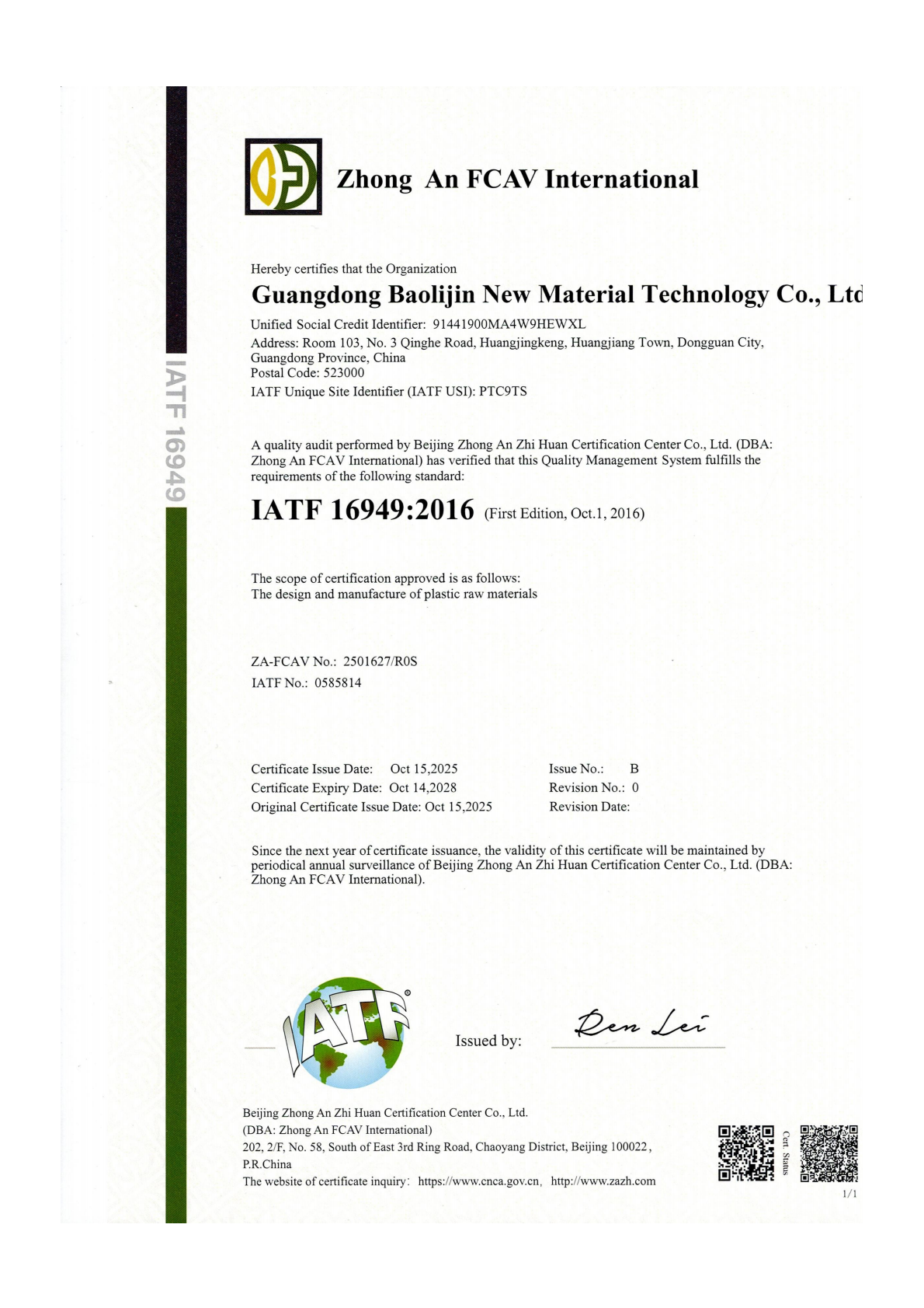
IATF 16949:2016 certification, certificate No. ZA-FCAV No.: 2501627/R0S, IATF No.: 0585814, valid 15 October 2025 to 14 October 2028.
Comparison Table: How LFT Carbon Fiber Composite Plastic Addresses Each Design Requirement
The table below maps the requirement that robotics engineers actually write in a specification to the property that answers it, using only documented values. The right-hand column states the comparison basis honestly, because the aluminum comparison figures come from a single documented production project rather than from a controlled cross-material test program.
| Design requirement | LFT carbon fiber composite plastic | Basis / standard | Comparison note |
|---|---|---|---|
| Carry structural load without deflection | Flexural modulus 30,700 MPa; flexural strength 510 MPa | ISO 178 | Stiffness is achieved in a molded part rather than an assembled metal weldment |
| Absorb impact without fracture | Izod impact 40 kJ/m² | GB/T 1843 | Long 5–25 mm fibers provide pull-out length that short-fiber compounds do not have |
| Deform before failing | Elongation at break 7.8% | Product parameter data | Matrix plasticity precedes crack propagation instead of brittle failure |
| Minimize moving mass | Density 1.28 g/cm³ | Product parameter data | 42% weight reduction compared with aluminum in a documented production project |
| Control part cost | 18% cost reduction compared with aluminum | Documented production project | Result reflects one high-volume Tier 1 program, not a universal cost guarantee |
| Integrate with aluminum frames | CTE 28 ppm/℃, compatible with aluminum | Documented production project | Reduces differential expansion at bolted joints under thermal cycling |
| Survive electrical and fluid exposure | UL94 V0 and IP6K9K compliance | Documented production project | Relevant to battery housings and to robotics parts exposed to coolant or cleaning |
| Support series production | Low float fiber formulation | Documented production project | Selected for high-speed mass production at 120,000 units per year |
Compliance and Quality Evidence Buyers Can Verify
Robotics buyers evaluating a long-fiber composite supplier are usually asked by their own quality function to confirm management-system certification before a sample is even requested. Polygram holds three relevant certifications, each with a traceable certificate number and validity period.
| Certification | Certificate number | Issuing authority | Validity |
|---|---|---|---|
| ISO 9001:2015 / GB/T 19001-2016 | IAS25924Q1858R0S | Guangdong ZQ Certification Service Co., Ltd. | 22 Oct 2024 – 21 Oct 2027 |
| IATF 16949:2016 | ZA-FCAV No.: 2501627/R0S; IATF No.: 0585814 | Beijing Zhong An Zhi Huan Certification Center Co., Ltd. (Zhong An FCAV International) | 15 Oct 2025 – 14 Oct 2028 |
| Medical Device Management System — GB/T 42061-2022 / ISO 13485:2016 | 64625B8031170R0S | ZhongRen HeZong Certification (Shenzhen) Co., Ltd. | 11 Mar 2025 – 10 Mar 2028 |
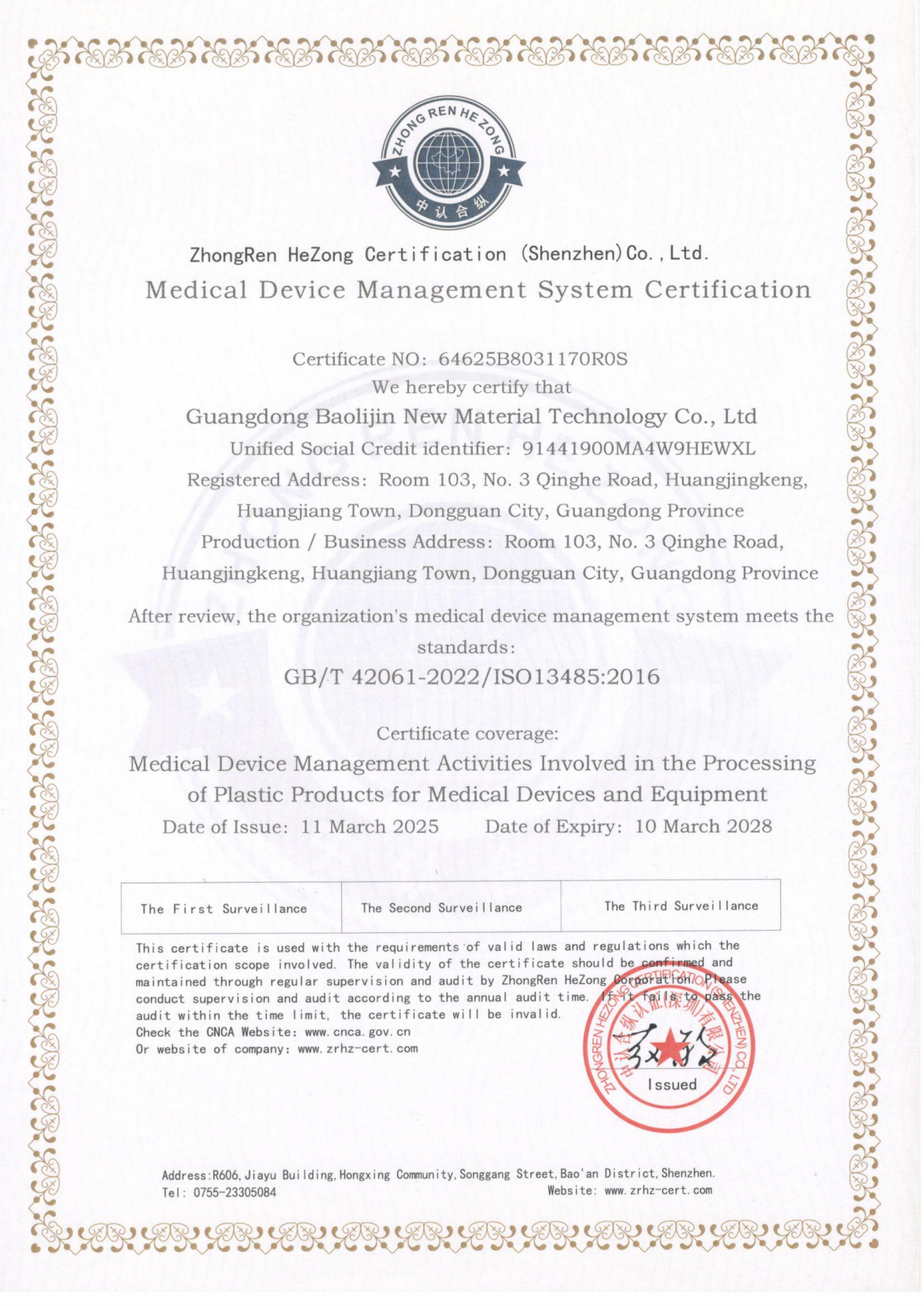
Medical Device Management System certification covering the processing of plastic products for medical devices and equipment, certificate No. 64625B8031170R0S.
The medical scope is worth noting for a second reason. It demonstrates that the same compounding and injection-molding operation can run under a controlled quality system that extends beyond general industrial requirements — a useful signal when a robotics application moves into laboratory, cleanroom or healthcare environments.
Frequently Asked Questions
Conclusion: Design for the Impact, Then Confirm the Stiffness
Robotics hardware does not need a material that is stiff or tough. It needs a material where the stiffness floor and the impact ceiling are both satisfied in the same molded part, at a mass the joint can afford. LFT carbon fiber composite plastic addresses that requirement through reinforcement architecture rather than through a compromise: fiber lengths of 5–25 mm provide the pull-out length that dissipates impact energy, while the same reinforcement delivers 350 MPa tensile strength, 510 MPa flexural strength and 30,700 MPa flexural modulus at 1.28 g/cm³ density.
The practical sequence for an evaluation is straightforward. Define the impact event and the stiffness floor. Select resin system and fiber loading against both. Confirm that tool design and process control will preserve fiber length. Validate against ISO 527-2, ISO 178 and GB/T 1843 on parts from a real tool. Then confirm the supplier's management-system certifications cover your application scope.
Polygram — Guangdong Baolijin New Material Technology Co., Ltd — operates that sequence as a single ODM scope covering material design, mold development and injection molding, with ISO 9001:2015, IATF 16949:2016 and ISO 13485:2016 certification and a documented 2018–2026 series production record at 120,000 units per year.
Next Step: Test the Balance on Your Own Part Geometry
Impact and stiffness performance is decided by the combination of grade, fiber loading and tool design — not by a catalogue page. Polygram supplies LFT carbon fiber composite plastic samples, grade-level property data and ODM quotations for robotics, low-altitude economy, aerospace and new energy vehicle programs. Minimum order quantity is 50 units and standard lead time is 30 days.
Request a sample or quotation: www.carbolft.com | Email: baolijin@carbolft.com | WhatsApp: +86 18664191149
Download the full product brochure: Polygram LFT Carbon Fiber Composite Plastic Brochure (PDF)

Engineering support for robotics programs: material design, mold development and injection molding handled as one ODM scope.
Have Questions or Need More Details?
Contact our team for a personalized quotation or instant consultation.
Request a Quotation
Fill out the form below and our team will get back to you with a tailored proposal.
WhatsApp Direct Chat
Prefer to chat in real-time? Message us on WhatsApp for instant assistance & quick answers.
- Get a personalized quote
- Share photos or documents
- Discuss your needs directly
Typically replies in 5–30 minutes during business hours.