
Grinding Wheel Setup Guide: Speed, Infeed and Flange Parameters
Metal grinding performance is decided before the first spark. A grinding wheel removes steel predictably only when three parameter families are matched to the machine and the job: the surface speed delivered by the spindle, the depth-of-cut infeed applied per pass, and the flange and mounting geometry that hold the disc on the spindle.
This technical guide documents the parameter bands used in metal grinding operations — surface speeds of 30–80 m/s, infeed of 0.005–0.05 mm per pass with longitudinal and crossfeed movements, and balanced flanges covering at least one-third of the wheel diameter — and converts them into a selection parameter checklist for workshops, contractors and buyers specifying metal grinding discs, metal grinding wheels and T27 depressed center discs for angle grinders and fixed grinding machines.
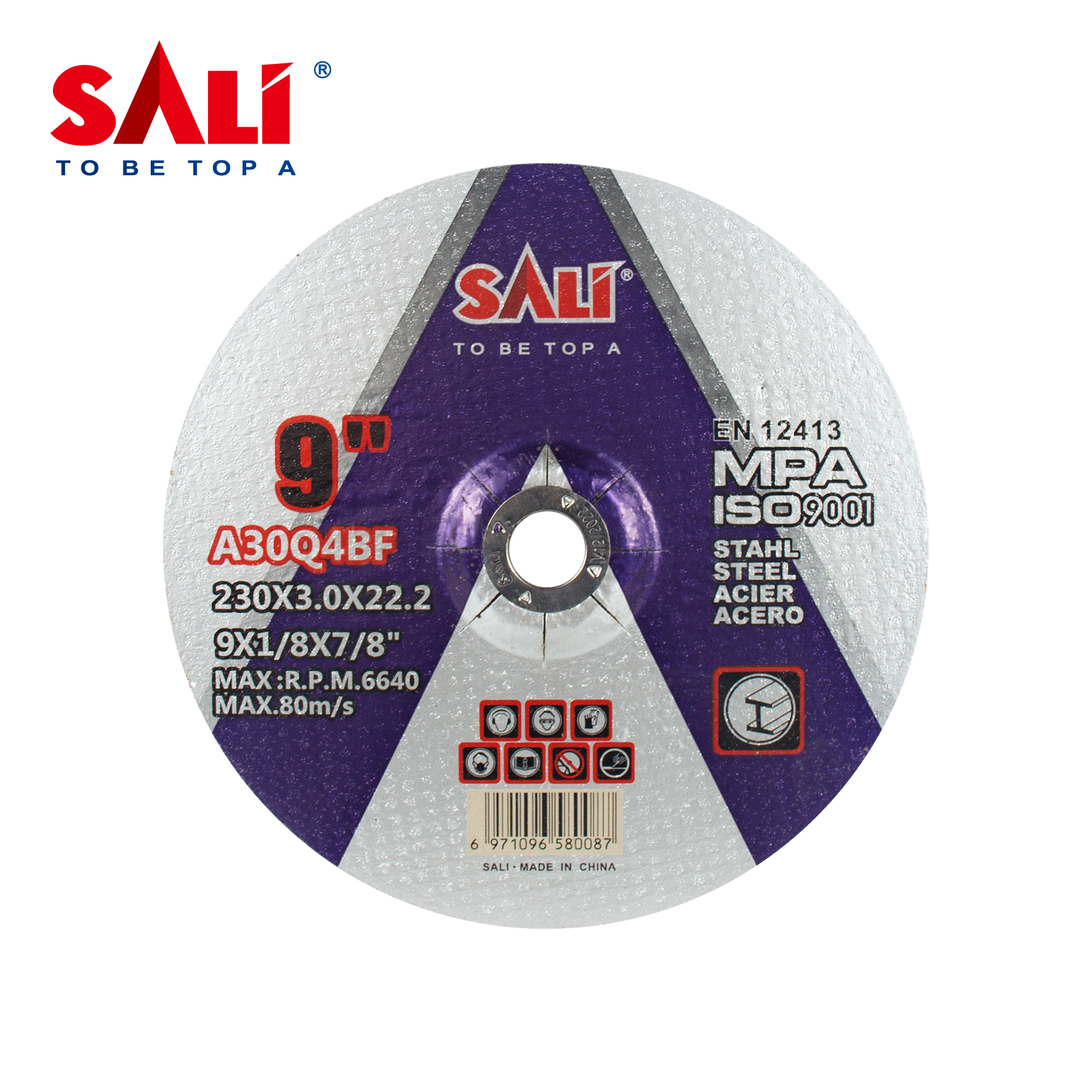
Problem Definition: Parameter Mismatch Is Often Reported as a Wheel Defect
Most grinding problems that reach a supplier as a quality claim are traceable to a parameter decision made at the machine, not to the abrasive itself. Three mismatches account for the majority of complaints:
- Speed mismatch. The equipment rotation speed must strictly remain within the Maximum Operating Speed (MOS) printed on the wheel label. When a disc rated for a given MOS is run on a spindle that can exceed it, the burst risk rises with the square of the speed, not linearly.
- Infeed mismatch. Excessive pressure causes heat buildup, glazing and wheel fracturing; infeed that is set far below the working range (0.005–0.05 mm per pass) allows abrasive grains to dull instead of fracturing, and the wheel stops cutting.
- Flange mismatch. Mounting requires balanced flanges that cover at least one-third of the wheel diameter, equipped with soft blotters for even pressure distribution. Undersized flanges concentrate clamping force near the bore, which is where cracking starts.
Secondary causes include expired or moisture-damaged consumables. Resin-bonded discs are moisture-sensitive and their bonding agents degrade with age, which is why expired wheels should never be mounted regardless of how well the machine is set up.
Industry Background: Metalworking Sets the Demand Pattern
The parameter discipline described in this guide is not a niche topic. The global grinding wheels market was estimated at USD 7.12 billion in 2025, and the metalworking segment led the market with a revenue share of 47.2% in 2025 — that is, roughly half of all bonded abrasive wheel revenue is consumed by metal cutting and grinding work.
Regionally, Asia Pacific held the largest share of 2025 revenue, reported at approximately 41.3% to 42.7% across major commercial research publications, with the variation attributed to methodology differences. For buyers qualifying a supply chain, that concentration matters: most grinding wheel capacity, and most parameter tuning expertise, sits in the same region.
Compliance framing is equally consistent. EN 12413:2019 specifies the safety requirements for bonded abrasive products including grinding wheels, and grinding wheels of agglomerated abrasives are classified under HS Code 6804.22 in international trade. In practice, these two references define what a compliant wheel label must show and how the product is cleared through customs — which is why MOS, dimensions and marking discipline appear on every serious buyer's specification sheet.
SALI Tools is the self-owned brand of ZHEJIANG SALI ABRASIVE TECHNOLOGY CO., LTD., a manufacturer founded in 2003 in Zhejiang, China, producing cutting discs, grinding discs, flap discs and power tools for export to more than 160 countries and regions. The company holds ISO 9001 and ISO 14001 certifications, and its abrasives carry MPA and EN12413 certification.
Detailed Solution: The Three Parameter Families That Must Match
1. Surface Speed: 30–80 m/s Inside a Fixed Maximum Operating Speed
A grinding wheel performs material removal through high-speed primary rotation. The drive spindle spins the wheel at surface speeds typically between 30 and 80 m/s. That rotation imparts high kinetic energy to the abrasive grains on the wheel surface and provides the core cutting force required to shear off microscopic metal chips.
The band is an operating range, not a target to be pushed. The hard ceiling is the Maximum Operating Speed printed on the wheel label, and SALI metal grinding discs are rated for high-speed operation up to 80 m/s (13,300 RPM). Two rules follow from this:
- Verify that the tool's maximum rated RPM sits below the wheel's MOS before mounting.
- Never treat a higher-MOS wheel as a permit to run a machine faster; the machine's own rated speed governs.
Speed also interacts with the other two parameters. At the high end of the band, each abrasive grain does more work per contact and the wheel behaves more aggressively; at the low end, the same infeed removes less material per revolution and heat has more time to accumulate in the workpiece.
2. Infeed and Feed Motion: 0.005–0.05 mm per Pass
To cover the entire target surface, relative feed movements are applied between the grinding wheel and the workpiece. Three motions are relevant:
- Depth-of-cut infeed — sets the removal thickness, usually 0.005 to 0.05 mm per pass.
- Longitudinal feed — pushes the wheel along the length of the workpiece.
- Crossfeed — advances the wheel across the width so successive passes overlap.
On fixed grinding machines these motions are machine-controlled. On portable angle grinders the operator reproduces them manually: the infeed is the pressure applied into the workpiece, and the longitudinal and crossfeed movements are the sweep along a weld seam and the step-over to the next track. That is why operator technique belongs in the parameter conversation rather than in a separate chapter on skill.
Practical anchor: 0.005 mm per pass is a finishing-scale cut; 0.05 mm per pass is a stock-removal-scale cut. Choosing where to sit inside that range is a decision about required surface finish versus cycle time — not a decision about how hard the operator can push.
3. Self-Sharpening Bonded Structure: The Feedback Loop Behind the Infeed Range
Operationally, the wheel relies on a self-sharpening mechanism enabled by its bonded structure. As individual abrasive grains dull and grinding resistance rises, the increased mechanical stress fractures either the dull grain itself or the surrounding bond, dislodging worn particles to expose fresh, sharp cutting edges.
This feedback loop explains why the infeed range is bounded on both sides. The bond needs a certain level of mechanical stress to renew the cutting face; the bond must also hold the grain long enough to complete a cut. SALI metal grinding discs use a resinoid bond matrix with aluminium oxide grain in grades A24Q4 BF and A30Q4 BF, optimized to minimize disc wear while keeping the self-sharpening behavior active. Where more aggressive removal or longer life is required, reinforcement and abrasive formula are the two variables that can be adjusted without changing the machine setup.
4. Flange and Mounting Geometry: One-Third Coverage, Blotters and Balance
Flange selection is the parameter most often decided by habit rather than specification. The documented requirement is unambiguous: mounting requires balanced flanges that cover at least one-third of the wheel's diameter, equipped with soft blotters for even pressure distribution.

Three checks make this parameter operational:
- Diameter coverage. Measure the flange face against the wheel diameter. One-third is a minimum, not an ideal.
- Condition. Flanges must be matching and undamaged; worn or burred flange faces cannot distribute pressure evenly.
- Blotters. Paper or rubber blotters sit between flange and wheel to spread clamping load and protect the bond near the bore.
Balance belongs to the same parameter family. A perfectly balanced center design reduces machine chatter, protects the grinder motor and lessens operator fatigue — and chatter, in turn, corrupts the infeed the operator thinks they are applying.
Safety and Control Points That Sit Outside the Three Parameters
Parameter matching does not remove the need for inspection, guarding and extraction. The following control points apply to metal grinding operations and should be treated as pass/fail gates:
- Ring test. Perform a ring test on vitreous wheels to detect hidden cracks; never use a dull-sounding wheel.
- Dry run. Run the fitted wheel empty with the guard in place for 1–3 minutes before starting work, standing clear of the rotation plane.
- Guard coverage. The safety guard must cover at least 180° and must never be removed.
- PPE. Impact-rated face shields, safety glasses, dust masks and hearing protection.
- Dust control. Continuous local exhaust ventilation with a minimum hood velocity of 1.5 to 2.5 m/s is required to control dust and prevent accumulation of abrasive particles and metal fines during dry grinding.
- Technique. Maintain a 15°–30° grinding angle on portable grinders and stand outside the direct burst line. Never use thin cut-off wheels for side grinding, and never use grinding wheels for deep cutting.
- Material compatibility. Match wheel type to the workpiece; standard wheels must not be used on soft metals such as aluminium or copper, or on wood and plastic, because loading causes violent wheel burst.
Ambient and coolant conditions also belong to the setup. Grinding wheels operate best between 15°C and 25°C with relative humidity of 50% to 60%, because extreme temperatures and excessive humidity weaken bonding agents. Where liquid coolants are used, a fluid pH between 7 and 9 prevents chemical erosion of the bond, and the wheel must spin empty for 3 to 5 minutes after wet operation to purge fluid and prevent unbalancing.
Step-by-Step Breakdown: A Parameter Matching Workflow
The workflow below sequences the parameters in the order they constrain each other, so that a change in one step does not invalidate a decision made earlier.
- Define the operation. Weld seam smoothing, deburring and edge chamfering, rust and mill scale removal, casting and forging cleaning, and surface shaping each require a different balance of aggressiveness and finish.
- Read the tool first. Record the grinder's maximum rated RPM and confirm that it sits below the wheel's Maximum Operating Speed.
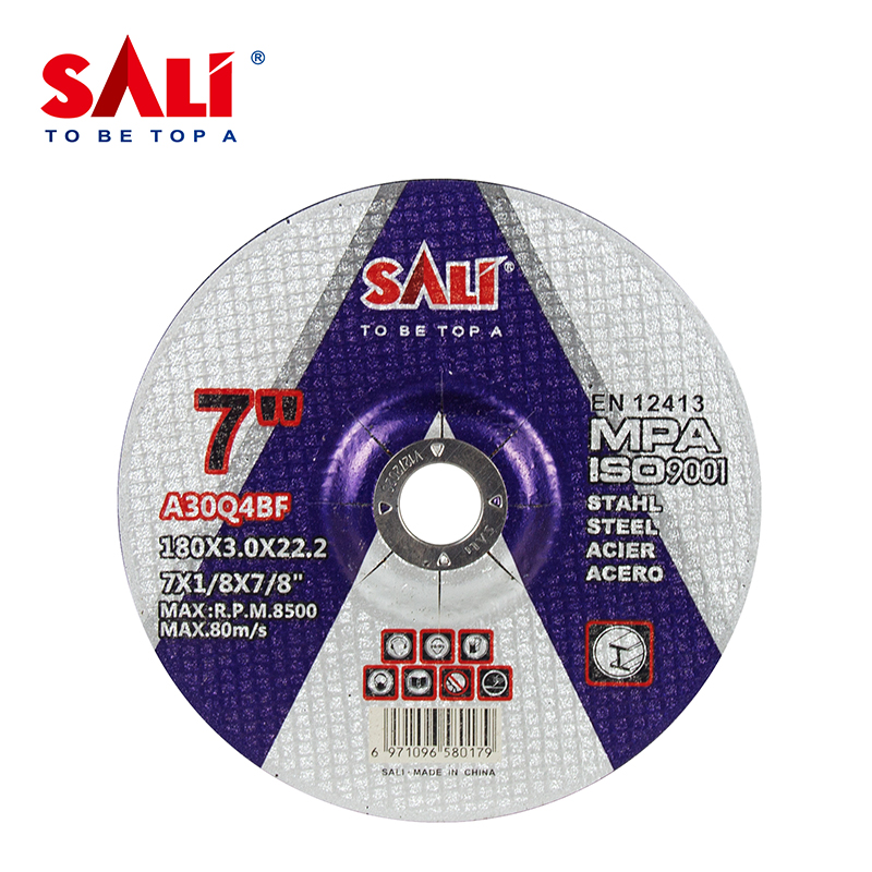
- Select diameter and type. Match disc diameter to reach and access, and choose flat or depressed center geometry. Available diameters in the SALI metal grinding disc range include 100 mm (4 inch), 115 mm (4.5 inch), 125 mm (5 inch), 180 mm (7 inch) and 230 mm (9 inch).
- Match the abrasive to the workpiece. Aluminium oxide (A) grain is applied to carbon steel, alloy steel, iron, weld joints and structural steel; white aluminium oxide (WA) is used for stainless steel (Inox), where a sulfur-free and chlorine-free bond avoids discoloration.
- Choose reinforcement. Fiber net quantity of 2 pcs or 3 pcs provides the anti-burst protection appropriate to the wheel size and duty cycle.
- Confirm flange and blotter geometry. Flange face at least one-third of the wheel diameter, undamaged, with blotters fitted.
- Inspect, ring test and dry run. Reject cracked, chipped, bent or moisture-damaged wheels; ring test; then dry run 1–3 minutes with the guard in place.
- Set the cutting parameters. Establish infeed within 0.005–0.05 mm per pass, then run longitudinal and crossfeed passes across the full surface.
- Set the control environment. Guard covering at least 180°, PPE fitted, and local exhaust ventilation verified at 1.5–2.5 m/s hood velocity.
- Record and reorder. Log the combination of diameter, grade, infeed and tool that produced the required finish, and use it as the reorder specification.
Table 1 — Parameter Reference for Metal Grinding Operations
| Parameter | Documented value / requirement | What goes wrong outside the value | Where it is controlled |
|---|---|---|---|
| Surface speed | Typically 30–80 m/s | Low speed leaves heat in the workpiece; high speed increases energy per grain | Machine spindle / tool rating |
| Maximum Operating Speed | Value printed on the wheel label; SALI discs rated to 80 m/s (13,300 RPM) | Exceeding MOS raises burst risk | Wheel marking + pre-mount check |
| Depth-of-cut infeed | 0.005–0.05 mm per pass | Too heavy: heat buildup and fracturing. Too light: grains dull, wheel stops cutting | Operator / machine infeed setting |
| Feed motions | Longitudinal and crossfeed movements across the surface | Incomplete surface coverage, uneven stock removal | Machine table or operator sweep |
| Flange coverage | At least one-third of wheel diameter, balanced, with soft blotters | Concentrated clamping force, bore cracking, wheel imbalance | Mounting hardware |
| Guard coverage | At least 180°, never removed | Direct exposure to burst fragments and debris | Tool guard |
| Dust extraction | Local exhaust ventilation at 1.5–2.5 m/s hood velocity | Abrasive particle and metal fines accumulation | LEV system |
| Grinding angle (portable) | 15°–30° | Excessive pressure, heat buildup, wheel fracturing | Operator technique |
| Ambient conditions | 15–25°C, 50–60% relative humidity | Weakened bonding agents, compromised structural integrity | Storage and workshop environment |
| Coolant pH (wet operation) | 7–9, then spin empty 3–5 minutes | Chemical erosion of the bond; residual fluid causes unbalancing | Coolant management |
Table 2 — SALI Grinding Wheel Documented Specification Options
SALI metal grinding discs are offered with documented options across abrasive, reinforcement, geometry and packaging. The following specification categories are drawn from the product data for the SALI Grinding Wheel range (models A0200001 through A0200034 series).
| Specification category | Documented options | Selection relevance |
|---|---|---|
| Abrasive material | Aluminium Oxide A30Q4 BF (black), Aluminium Oxide A24Q4 BF | Aggressive removal with controlled wear on steel |
| Bond and backing | Resinoid bond, fiberglass mesh, aluminum oxide grain | Self-sharpening behavior and anti-burst reinforcement |
| Fiberglass reinforcement | 2 pcs or 3 pcs fiber net | Higher mesh count for heavier duty cycles |
| Wheel type | T27 black, T42 black | Depressed center geometry for angle grinding access |
| Diameter range (standard) | 100 mm (4"), 115 mm (4.5"), 125 mm (5"), 180 mm (7"), 230 mm (9") | Match to tool size and reach |
| OEM diameter and thickness | Outer diameter 100 mm – 400 mm (4"–16"); thickness 1.0–1.6 mm ultra-thin, 2.0–6.0 mm standard | Custom programs and heavy-duty configurations |
| Bore and shape | 16 mm, 22.23 mm, 25.4 mm bore; flat (Type 41) or depressed center (Type 42 / Type 27) | Spindle and flange compatibility |
| Grain and hardness | Grit sizes 24#–120#, tailored bond hardness | Balance between grinding speed and wear resistance |
| Certification marking | MPA, EN12413, ISO 9001, MSDS | Compliance documentation for procurement |
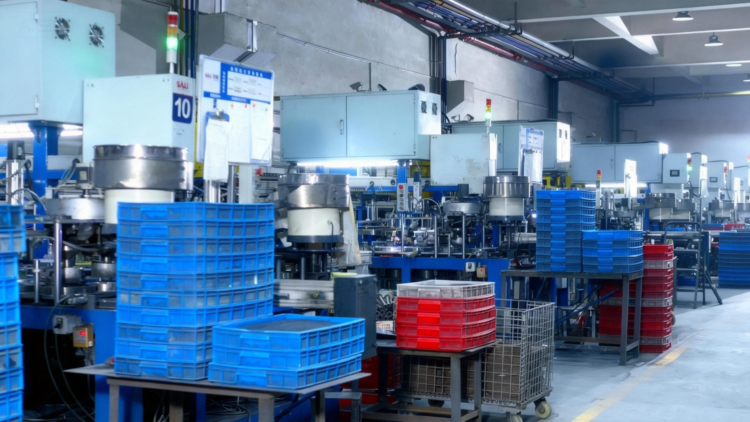
Table 3 — Compliance and Trade Reference Points
| Reference | Type | Scope | Why it matters to a grinding setup |
|---|---|---|---|
| EN 12413:2019 | European standard (CEN) | Safety requirements for bonded abrasive products including grinding wheels | Defines the marking and safety framework behind MOS discipline |
| MPA | Certification | Carried by SALI metal grinding discs | Third-party verification used in European procurement |
| ISO 9001 / ISO 14001 | Management system certification | Held by ZHEJIANG SALI ABRASIVE TECHNOLOGY CO., LTD. | Supports batch traceability and consistent wheel parameters |
| HS Code 6804.22 | Trade classification | Grinding wheels of other agglomerated abrasives or ceramics | Import documentation and duty classification |
Use Cases: Which Parameters Matter in Which Project Type
Parameter weighting shifts by application. The scenarios below reflect the industries and project types for which SALI grinding wheels are specified.
Steel construction and infrastructure
Structural steel and building construction work is dominated by weld seam smoothing, deburring, edge chamfering and mill scale removal. Infeed sits in the middle-to-heavy part of the 0.005–0.05 mm per pass range, and flange condition is critical because discs are changed frequently on site. Middle East project experience illustrates the volume profile of this work: a project involving a quantity of 10 million pieces was completed within 5 years for fabrication and on-site processing purposes, and achieved stable operation results.
Pipeline, energy infrastructure and pressure work
Pipeline and energy infrastructure work requires weld seam smoothing with controlled heat input. Surface speed consistency matters more than maximum aggression, since localized overheating can affect the joint area. Crossfeed discipline — overlapping each pass with the previous one — determines whether the seam is genuinely blended or merely polished.
Shipbuilding and offshore engineering
Heavy plate preparation involves rust and mill scale removal across large areas. Here the infeed decision is driven by consumable economics: a slightly heavier cut inside the documented range reduces the number of passes, while the resinoid bond continues to self-sharpen. Guard coverage and extraction are non-negotiable in confined spaces.
Rail transit and heavy equipment manufacturing
Casting and forging cleaning involves irregular surfaces where infeed must be modulated pass by pass. Type 27 depressed center geometry allows the grinding face to be presented at the 15°–30° angle needed to reach into fillets without loading the disc edge.
Industrial MRO and equipment overhaul
Maintenance and overhaul work mixes materials in the same shift. The practical rule is to keep wheel type matched to workpiece: resinoid bonded aluminium oxide discs for carbon, alloy and structural steel; white aluminium oxide formulations for stainless steel and Inox, so that grinding does not discolour the surface.
Distribution and channel supply
For distributors, parameter discipline translates into fewer returns. SALI's channel experience in Central Asia is a reference point: in Uzbekistan, a wholesaler client has used SALI products for more than 9 years, and by 2024, the wholesaler's sales volume had increased 21 times compared with the first year as a SALI agent in 2018. Stable quality, complete specifications and dependable supply support were the stated reasons.
FAQ
What must be verified before a metal grinding wheel is mounted?
Five checks, in order. First, the equipment rotation speed must strictly remain within the Maximum Operating Speed printed on the wheel label; SALI metal grinding discs are rated for high-speed operation up to 80 m/s (13,300 RPM). Second, perform a ring test on vitreous wheels to detect hidden cracks, and never use a dull-sounding wheel. Third, confirm that balanced flanges cover at least one-third of the wheel diameter and are fitted with soft blotters for even pressure distribution. Fourth, confirm the safety guard covers at least 180° and is not removed. Fifth, verify continuous local exhaust ventilation at a minimum hood velocity of 1.5 to 2.5 m/s. Wheels that are cracked, chipped, bent, moisture-damaged or expired must be rejected. SALI products carry MPA and EN12413 certification, and the company holds ISO 9001 and ISO 14001 certification.
Can grinding wheel parameters be customized to a specific metal grinding operation?
Yes. Under its OEM / ODM program, SALI customizes the parameters that influence both cutting behavior and mounting compatibility: abrasive grain type (brown aluminium oxide for metal, white aluminium oxide for stainless steel and Inox, zirconia for heavy duty, silicon carbide for stone and cast iron), grit sizes from 24# to 120#, bond hardness, fiberglass mesh reinforcement in single, double or triple layers, outer diameters from 100 mm to 400 mm (4"–16"), thicknesses of 1.0–1.6 mm for ultra-thin and 2.0–6.0 mm for heavy-duty cutting and grinding, and bore sizes of 16 mm, 22.23 mm or 25.4 mm. Geometry can be flat (Type 41) or depressed center (Type 42 / Type 27), and labels, disc colours, artwork, barcodes and safety markings can be produced to a distributor's own branding.
Which parameters have the largest effect on cost per grind?
Cost per grind is driven by wear, not by unit price alone, and wear is driven by setup. Running infeed inside the documented 0.005–0.05 mm per pass range keeps the self-sharpening mechanism active, so the wheel renews its cutting face instead of glazing and being discarded early. Correct flange geometry prevents mounting-related failures that consume a disc before its abrasive is spent. Matching the abrasive grade to the workpiece avoids extra passes and rework. SALI's resinoid bond matrix is formulated to minimize disc wear, and the export-ready packaging — moisture-resistant colour boxes and outer cartons — protects the consumable between shipment and use, which protects the stored value of an order. For SALI brand orders, the MOQ is as low as 1 carton (approximately 500–1000 pcs), which allows a workshop to standardize on a verified setup without committing to a container volume.
Can we validate a grinding wheel setup with samples before a project quantity?
Sample validation is standard practice for SALI buyers. New clients can order samples for testing, and sample fees are fully refunded on the first bulk order; regular partners receive free new samples. Validation is supported by remote inspection: clients can access the testing laboratory cameras to watch real-time batch testing such as burst speed, cutting efficiency and durability, or request customized testing metrics. Every production batch is inspected in-house, and the target is 100% testing. This matters for parameter work specifically, because the burst speed and durability figures a buyer validates on a sample are the same figures that will be relied on when the wheel is run near the Maximum Operating Speed on site.
What is the lead time for standard and customized grinding wheel orders?
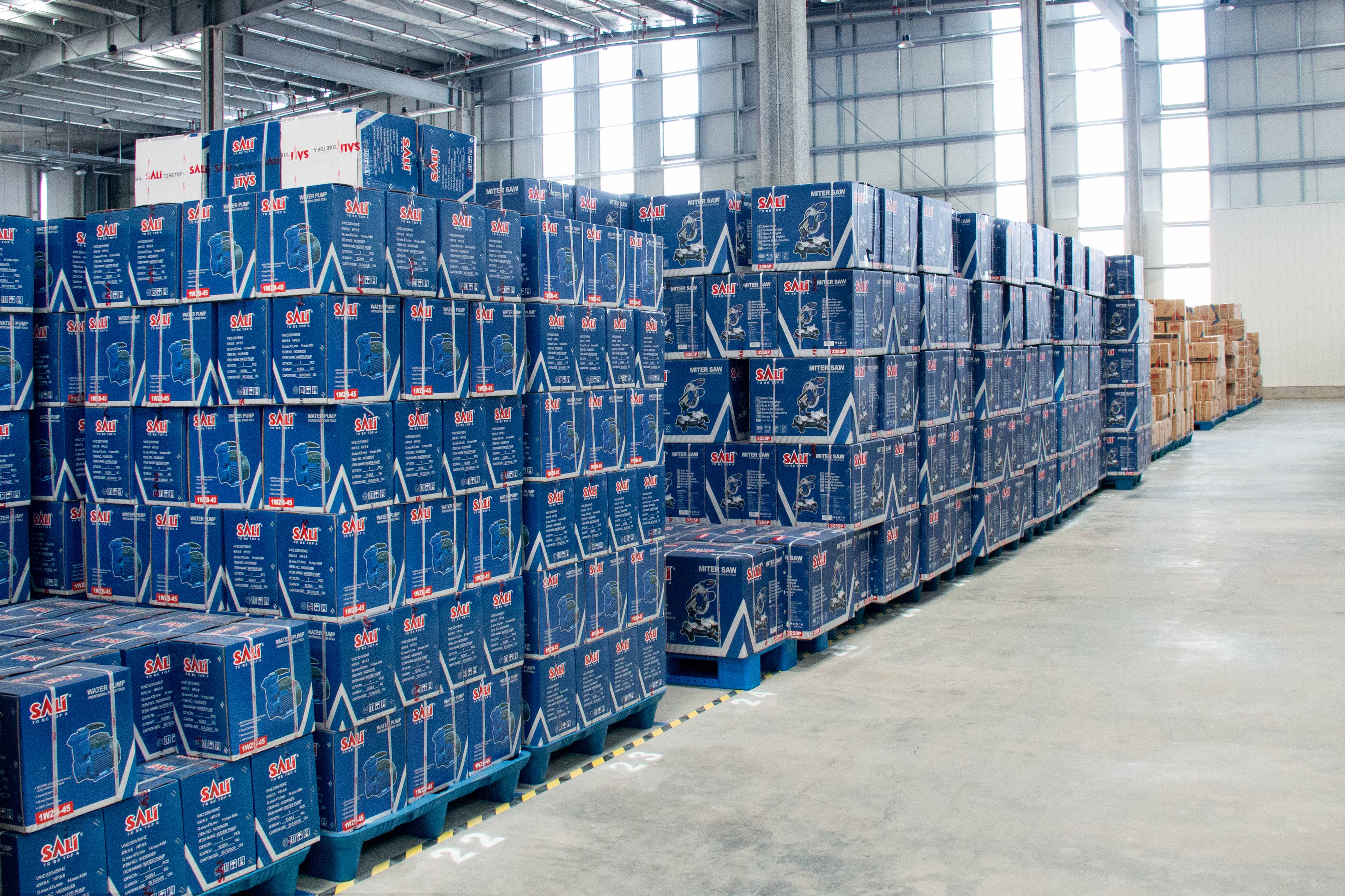
Standard SKUs are the fast path: SALI maintains 85% of standard SKUs in ready stock across an 8,000 m² warehouse with capacity for 12,000 m³ of goods, enabling same-day dispatch for regular orders. Monthly capacity is 12.5 million pieces at a factory in Yongkang, Zhejiang, with a 30,000 m² construction area. For OEM orders, lead time is 30 to 45 days from design confirmation to final delivery. To start a parameter-matched program, request a sample or quotation at salimarketing@pcsali.com, message WhatsApp +86 188-6758-6946, or download the full SALI Tools Brand Product Catalog.
Conclusion
A grinding wheel is not selected by diameter alone. It is selected by matching three parameter families — surface speed inside the 30–80 m/s operating band and always below the labelled Maximum Operating Speed, depth-of-cut infeed between 0.005 and 0.05 mm per pass with longitudinal and crossfeed motions, and balanced flange geometry covering at least one-third of the wheel diameter with soft blotters. The self-sharpening resinoid bonded structure is what makes that infeed range work: it renews the cutting face as grains dull, provided the setup gives it enough mechanical stress to do so.
Safety and control points complete the picture rather than sitting apart from it: ring testing before mounting, a guard covering at least 180°, impact-rated PPE, and local exhaust ventilation at 1.5–2.5 m/s. Where a project repeats — fabrication jobs, pipeline work, shipbuilding plate preparation, MRO — the combination that produced the required finish should be recorded and reused, because reproducibility is what turns a grinding wheel from a consumable into a controlled process input.
Next step: build the checklist around your own machine and workpiece. SALI Tools supplies metal grinding discs for carbon steel, structural steel and stainless steel in 100 mm, 115 mm, 125 mm, 180 mm and 230 mm diameters, with MPA and EN12413 certification, and supports OEM programs from 100 mm to 400 mm. Request samples or a quotation: salimarketing@pcsali.com | WhatsApp +86 188-6758-6946 | www.salitools.com. Download the SALI Tools Brand Product Catalog for the full specification range.
Have Questions or Need More Details?
Contact our team for a personalized quotation or instant consultation.
Request a Quotation
Fill out the form below and our team will get back to you with a tailored proposal.
WhatsApp Direct Chat
Prefer to chat in real-time? Message us on WhatsApp for instant assistance & quick answers.
- Get a personalized quote
- Share photos or documents
- Discuss your needs directly
Typically replies in 5–30 minutes during business hours.