
3D Scanner for Quality Control: From Certification to Shopfloor Inspection
When a quality engineer buys a 3D scanner, the real question is not only how many points per second it captures. It is whether the measurement data is trustworthy enough to sign off a part, feed a GD&T report, and support an ISO 9001 quality system. A 3D scanner for quality control must therefore bring together three elements: traceable accuracy, practical workflow, and enough flexibility to handle everything from a first article to an MRO component on the shop floor.
Problem Definition: Why Point-by-Point Inspection Is No Longer Enough
Traditional quality control tools — calipers, height gauges, and fixed gauges — measure isolated dimensions. They are effective for simple checks but structurally limited when parts contain freeform surfaces, deep cavities, thin walls, or complex assembly features. Coordinate measuring machines (CMMs) provide outstanding accuracy, yet they often require controlled laboratory conditions, long programming time, and workpiece handling that is impractical for large castings, sheet metal parts, or components that must remain on the production line.
Manufacturers are therefore shifting to non-contact 3D scanning. By capturing the full surface geometry in one measurement, a quality control 3D scanner enables 100% surface inspection instead of point sampling. It also generates a digital record that can be compared with CAD, analyzed for geometric tolerances, and archived for future traceability.
Industry Background: Quality Control Is the Largest 3D Scanning Application
The commercial case for optical metrology is strong. The global 3D scanning market was estimated at USD 4.28 billion in 2024, according to Grand View Research. Among all application segments, quality control and inspection accounted for the largest share of the 3D scanner market, according to Precedence Research. The automotive industry, in particular, is the largest end user of 3D scanning technology, using it for parts inspection and quality assurance. In parallel, the 3D automated optical inspection equipment market was valued at USD 2.74 billion in 2024, confirming that manufacturers are moving from offline, manual checks toward automated optical measurement.
These numbers explain why procurement teams are asking more disciplined questions about standards, accuracy levels, software integration, and supplier quality systems.
Detailed Solution: What a Quality-Ready 3D Scanning System Must Provide
SHINING 3D, a 3D vision technology company established in 2004, is one of the manufacturers that has built its industrial portfolio around this exact requirement. The company supplies metrology-grade 3D scanners, professional handheld scanners, and automated inspection systems to manufacturers worldwide. Its product range includes fixed optical scanners, wireless handheld scanners, dynamic tracking systems, and desktop automated inspection systems.
For quality control, the relevant question is not which single model is “best,” but which combination of accuracy, portability, automation, and certification fits the inspection workflow. SHINING 3D covers this spectrum:
- Fully automated desktop systems such as AutoScan Inspec2 for small precision parts.
- Fixed blue-light metrology scanners such as OptimScan Q12/Q9 and OptimScan Q12/Q9 HD for high-detail lab and robot-integrated inspection.
- Wireless handheld metrology scanners such as FreeScan Combo Series and FreeScan Omni Series for shopfloor mobility.
- Wireless dynamic tracking systems such as FreeScan Trak Nova Series for large objects and markerless measurement.
- Automation-ready configurations in the RobotScan Series for batch inspection and production line integration.
Certification and Traceability as a First-Class Requirement
Quality managers require confidence that the scanner can produce measurement data that is accepted by internal and external audits. SHINING 3D operates a precision accuracy laboratory accredited in accordance with ISO/IEC 17025. Metrology-grade scanners are acceptance-tested to international measurement standards such as VDI/VDE 2634 and ISO 10360. Depending on the model, products carry certifications including CE, FCC, ROHS, WEEE, KC, FDA, UKCA, IP50, TELEC, and TISAX. In addition, SHINING 3D is certified to ISO 9001 for quality management, ISO 14001 for environmental management, and ISO 45001 for occupational health and safety. These credentials matter because a 3D scanner is not only a measurement tool; it is part of a quality management system.

Step-by-Step Breakdown: From Physical Part to Inspection Report
A digital inspection workflow is repeatable, auditable, and faster than traditional manual measurements. The process follows a clear sequence.
Step 1: 3D Data Acquisition
The operator captures the physical object with a high-precision 3D scanner. Handheld laser scanners collect data quickly over large surfaces, while fixed structured-light scanners acquire fine detail on smaller components. The output is a dense point cloud or mesh that represents the as-built geometry.
Step 2: Data Processing and Alignment
Scan data is cleaned and aligned. Inspection software removes unnecessary background data and ensures that the scanned part is positioned correctly relative to the CAD model or an established datums system.
Step 3: CAD Comparison and Deviation Analysis
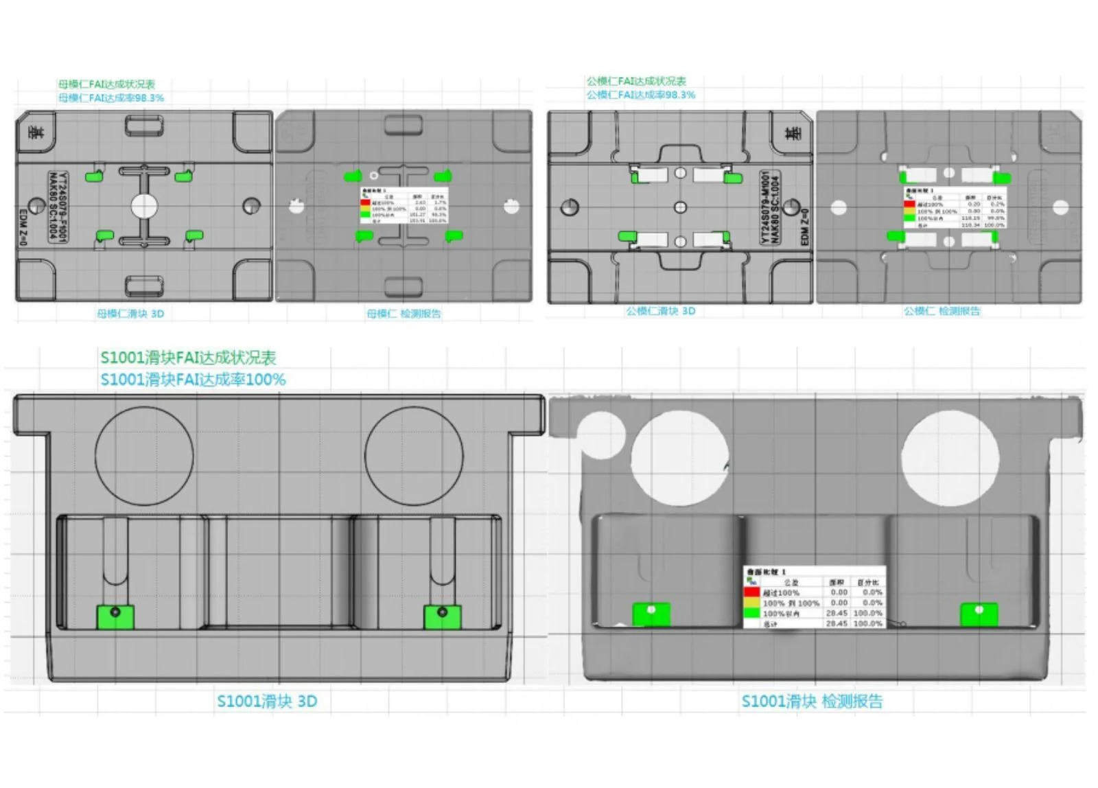
After alignment, the scanned mesh is compared to the nominal CAD model. The software generates color-map deviations that immediately show where the manufactured part differs from design. This step is especially useful for detecting warpage, shrinkage, or localized deformation.
Step 4: Dimensional Inspection and GD&T Evaluation
For engineering release, quality engineers need more than a color map. Inspection modules allow them to evaluate diameters, distances, angles, flatness, roundness, and other geometric dimensioning and tolerancing (GD&T) characteristics. SHINING 3D’s inspection module is integrated into selected scanners and is PTB-certified, giving quality teams a reliable built-in tool for dimensional analysis.
Step 5: Report Generation
The final step is generating an inspection report that can be shared with engineering, production, and customers. Reports can include color maps, measurement tables, tolerance results, and pass/fail conclusions. Because the data is digital, it can be stored for traceability and later referenced during audits.
Use Cases: Matching the Scanner to the Quality Task
3D Scanner for First Article Inspection
First article inspection requires full verification of a new or changed part before mass production starts. A 3D scanner can capture complete geometry, compare it with CAD, and validate critical dimensions much faster than a CMM program can be written. Desktop automated systems such as AutoScan Inspec2 are designed for small precision parts; handheld systems are more practical when the first article is a large sheet metal assembly or a machined housing.
3D Scanner for Sheet Metal Inspection
Sheet metal parts are thin, easily deformed, and often measured with expensive checking fixtures. A non-contact 3D scanner eliminates the risk of probes touching and bending the surface. It can also replace part-specific fixtures, allowing one scanning system to inspect multiple part shapes. The FreeScan Trak Nova Series has been applied in automotive sheet metal inspection because it requires no markers, works at high speed, and can be used directly on the shop floor.
3D Scanner for Mold and Tooling Inspection
Molds and stamping dies lose material through wear, and even small deviations change the final product. Optical fixed scanners such as OptimScan Q12/Q9 HD capture fine details on complex cavities, while handheld scanners can inspect large dies in place. The data is used for wear analysis, repair planning, and quality approval of new tooling.
3D Scanner for Automated In-Line Inspection
Automated inspection is becoming a production requirement, especially in consumer electronics and automotive component manufacturing. For high-speed and automated cells, blue laser scanners and structured-light scanners are integrated with robotic arms and turntables. The RobotScan Series is a SHINING 3D automation solution that combines a scanner, robot controller, and inspection software into a repeatable, batch-capable quality station.
3D Scanner for Shopfloor, Marine, Construction Machinery and MRO Inspection
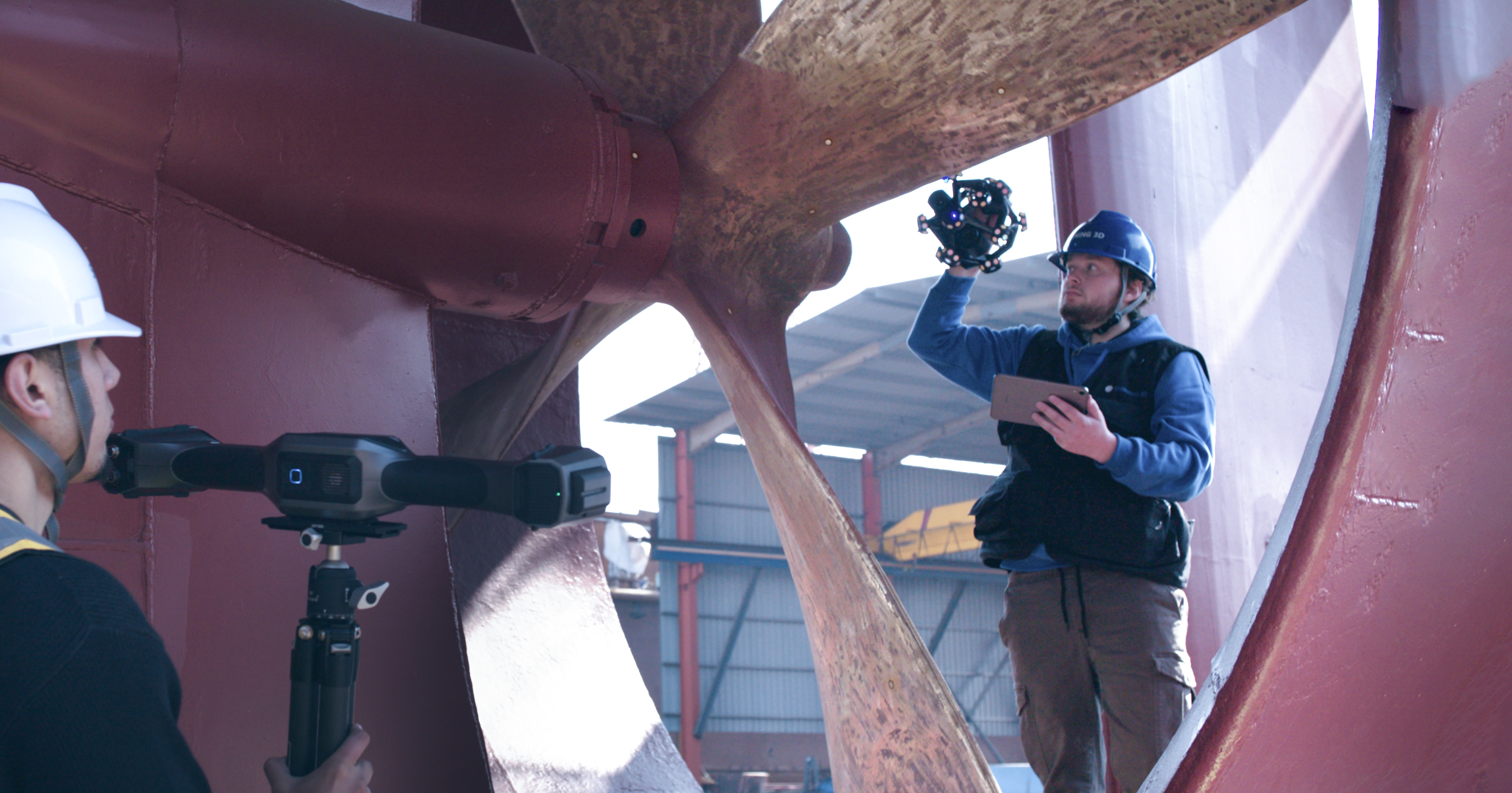
Large workpieces such as ship hull components, mining truck frames, and hydro-turbine parts cannot easily be moved into a metrology lab. Wireless handheld scanners and dynamic tracking systems allow the measurement team to go to the part. The FreeScan UE Nova and FreeScan Trak Nova have been used for mining equipment inspection, marine mold digitization, and MRO tasks because they support markerless scanning over large areas and operate in workshop conditions.
Comparison Table: Selecting a 3D Scanner for Quality Control
The table below compares representative SHINING 3D platforms using information from the product specification corpus. Accuracy figures listed are based on each model’s specification sheet.
| 3D Scanner Platform | Technology / Form Factor | Accuracy Level | Typical Quality Control Role |
|---|---|---|---|
| AutoScan Inspec2 | Automated desktop 3D inspection system; blue LED | Up to 0.01 mm | Small precision parts; batch inspection; FAI |
| OptimScan Q12/Q9 | Fixed metrology-grade blue LED structured-light scanner | 0.015 mm large range; up to 0.005 mm small range | Precision machined parts, electronic housings, lab inspection |
| OptimScan Q12/Q9 HD | High-precision fixed blue LED scanner | 0.01 mm large range; 0.004 mm small range | GD&T inspection, fine details, mold inspection |
| FreeScan Combo Series | Handheld hybrid light source (blue laser + infrared VCSEL) | 0.02 mm | Portable shopfloor inspection, automotive and casting parts |
| FreeScan Omni Series | Wireless standalone metrology 3D scanner with on-device inspection | 0.02 mm | Shopfloor inspection without a laptop; FAI and GD&T |
| FreeScan Trak Nova Series | Wireless dynamic tracking and scanning system | 0.02 mm | Large sheet metal parts, automotive body, heavy equipment |
Note: Volumetric accuracy should also be reviewed when measuring large parts. Systems with video photogrammetry (VPG) such as FreeScan Trak Nova or FreeScan Omni can control global error better during large-object scans.
FAQ
Does SHINING 3D meet ISO 9001 and metrology standards for quality control scanners?
Yes. SHINING 3D is certified to ISO 9001 for quality management and operates an ISO/IEC 17025 accredited accuracy laboratory. Its metrology-grade scanners are tested according to VDI/VDE 2634 Part 3 and/or ISO 10360 standards, depending on the model. This makes the inspection data suitable for ISO 9001 documentation and quality audits.
What accuracy can a 3D scanner for quality control achieve?
Accuracy depends on the scanner type and measurement range. In the SHINING 3D portfolio, the OptimScan Q12/Q9 HD delivers up to 0.004 mm in small-range mode, the OptimScan Q12/Q9 reaches 0.005 mm, the AutoScan Inspec2 achieves up to 0.01 mm, and handheld metrology scanners such as FreeScan Combo, FreeScan Omni, and FreeScan Trak Nova provide 0.02 mm certified accuracy.
Which scanner should I choose for automated in-line inspection?
For shiny, dark, or reflective parts, blue laser scanners like FreeScan Trak Nova or FreeScan Combo are often recommended because they handle difficult surfaces without developer spray. For very small components requiring fine-detail measurement, fixed structured-light scanners such as OptimScan Q12/Q9 HD are preferable. These scanners can be integrated with industrial robots through the SHINING 3D RobotScan solution for automated batch inspection and digital traceability.
What are the MOQ and delivery time for industrial scanners?
SHINING 3D supports an MOQ of 1 unit for industrial 3D scanners. Standard lead time is typically 30 to 45 days. Every scanner undergoes 100% testing before shipment, and after-sales support includes remote and onsite assistance.
How can I request a quote or discuss my quality control application?
If you are evaluating a 3D scanner for quality control, contact SHINING 3D directly by email at marketing@shining3d.com or visit the SHINING 3D website. A product specialist can help you select the right accuracy level, software workflow, and automation option for your part size and quality management system.
Next step: Download the SHINING 3D corporate 3D digitizing introduction brochure for a full overview of industrial scanners and solutions: SHINING 3D 3D Digitizing Introduction.
Conclusion
Quality control is no longer a separate room with a CMM. It is happening on the production line, inside large workpieces, and within automated cells. A 3D scanner for quality control gives manufacturers the ability to validate full-field geometry, generate traceable reports, and support ISO 9001 objectives with measured evidence. When selecting equipment, buyers should compare certified accuracy, compatibility with inspection software, markerless workflow, wireless flexibility, and integration capability.
SHINING 3D covers these requirements through a spectrum of fixed, handheld, wireless, and robot-integrated scanners. Whether you need a desktop scanner for electronic components, a blue-light system for mold details, or a wireless tracking scanner for a five-meter frame, the first step is defining your standard: the calibration certificate, the task, the report, and the parts that will be measured.