
Automated Inline Parts Inspection: Choosing the Right 3D Scanner for Your Production Line
Short answer: For automated inline parts inspection, select a full-field optical 3D scanner by six criteria — light source (blue laser for dark, reflective or machined surfaces; blue LED structured light for fine edges and small features), measuring volume (fixed heads below 500 mm; handheld and dynamic tracking systems for 500–2500+ mm components), traceable accuracy (VDI/VDE 2634 and ISO 10360 acceptance testing performed in an ISO/IEC 17025 accredited laboratory), cycle time (scan speed, marker-free tracking, automated reporting), shop-floor ruggedness (vibration, dust, ambient light, temperature), and software integration with robot controllers, PLCs and MES. Full-field optical scanning is typically 5–10x faster than discrete CMM probing on comparable parts, and it has no stylus to replace.
Moving inspection from a metrology lab onto a production line changes the selection criteria for a 3D scanner. In automated inline parts inspection, the scanner is no longer a standalone instrument — it is a sensor inside a cell, triggered by a robot or conveyor, gated by a PLC, and judged by whether it keeps pace with takt time. The right 3D scanner for quality control in this context is the one that matches your measuring volume and materials, carries traceable metrology accuracy, and integrates with your automation stack without part-specific fixtures or probe consumables.
SHINING 3D (Shining 3D Tech Co., Ltd.), founded in 2004 and headquartered in Hangzhou, China, develops high-precision 3D vision hardware and software and supplies metrology 3D scanners, professional 3D scanners, entry-level 3D scanners and dental 3D solutions. Its metrology portfolio — including the FreeScan Omni, FreeScan Combo, FreeScan Trak Nova and OptimScan series — is deployed in automotive, aerospace, energy, heavy machinery, electronics and mold manufacturing, and the company reported operating revenue above USD 220 million in 2025.
This guide is written for quality, manufacturing and automation engineers evaluating full-field 3D scanning as a replacement for, or a complement to, discrete probing on the line. It covers the inspection bottleneck driving the change, a technology selection framework, a step-by-step specification process, documented deployment cases, and the commercial terms that apply to OEM and ODM configurations.

The Inline Inspection Bottleneck: Points Versus Surfaces
Inspection has historically been organized around discrete probing. A coordinate measuring machine (CMM) touches a limited set of points, one at a time, inside an environment-controlled room. It remains the reference for absolute accuracy on critical features, but it is structurally difficult to move inline: it is stationary, environment-sensitive, and tied to programming and fixturing work that must be completed before a single measurement is taken.
Those preparation costs are substantial. In an aircraft component inspection case, a CMM required 2–3 days to set up the program and begin collecting data for a single part, and some parts required fixtures that took up to three days to design and manufacture. In stamping, a typical dedicated checking fixture takes 1.5 to 2 months to design and build, custom fixtures can cost thousands of dollars per part, and complex parts may require two separate fixtures.
Discrete probing also limits what can be verified. Key-point checks can miss shape deformations, springback and warpage on freeform surfaces, because data only exists where the probe touched. Non-contact full-field scanning captures the complete 3D geometry of a part in one measurement, which is what makes 100% surface inspection, automatic deviation mapping and GD&T evaluation of complex parts practical on a production timescale.
Probing systems carry recurring maintenance as well. A stylus is a wear item that must be replaced and recalibrated, and dedicated fixtures consume floor space and must be validated, stored and re-qualified. Optical scanning removes both line items from the maintenance budget.
Industry Background: Why Inline 3D Inspection Is Moving Onto the Line
The global 3D scanning market was estimated at USD 4.28 billion in 2024, driven by increasing use in quality control and prototyping (Grand View Research). Within that market, the quality control and inspection application segment held the largest share in 2024 (Precedence Research), and the wider 3D metrology market — scanners, coordinate systems and related sensors — was valued at USD 11.13 billion in 2024 (MarketsandMarkets).
Growth is concentrated where manufacturing is densest. Asia Pacific is projected to be the fastest-growing region for 3D metrology, with a CAGR of 8.0% through 2029 (MarketsandMarkets), while North America held a 37% revenue share of the 3D scanner market in 2024, led by aerospace and automotive demand (Precedence Research). Automotive remains the largest end-user of 3D scanning technology for parts inspection and quality control (Precedence Research).
Product mix shows the same bias toward precision. Structured light scanners dominated the 3D scanner product segment in 2024 because of their high precision in industrial applications, and short-range scanners (≤ 1 m) held the largest share on the strength of parts inspection requirements (Precedence Research). In the adjacent automated optical inspection equipment market — valued at USD 2.74 billion in 2024 and growing at a 7.32% CAGR (Market Research Future) — inline automated 3D inspection systems are increasingly replacing offline checks in the electronics sector to boost first-pass yields (Mordor Intelligence).
On the supply side, Hexagon, FARO and Carl Zeiss are recognized as Tier 1 global leaders in industrial metrology and 3D scanning (SNS Insider). SHINING 3D was recognized as an “Emerging Leader” in the global industrial metrology space by 360Quadrants in 2025 and reported 31% revenue growth in 2025, attributed to innovation in industrial metrology and global expansion.
How to Choose a 3D Scanner for Automated Inline Parts Inspection
Six factors determine whether a scanner works inside an automated cell rather than in a laboratory. They should be evaluated in order, because each one narrows the candidate list for the next.
1. Optical technology and light source
Blue laser projection is the practical choice for complex, shiny, reflective or dark and black surfaces — machined automotive alloys, sheet metal, castings — because it tolerates reflectivity and ambient light without developer spray. Blue laser line systems such as the FreeScan Trak Nova Series and the FreeScan Combo+ Wireless provide high scanning speed and ambient light immunity on fast-moving lines. Blue structured light (LED fringe projection) is the better fit for fine detail, sharp edges and small precision components such as electronic connectors, turbine blades and small cast housings, where feature fidelity matters more than raw coverage speed; the OptimScan Q12/Q9 HD uses blue LED fringe projection for this class of work. Systems such as the FreeScan Omni and FreeScan Combo Series combine blue laser with infrared VCSEL in one device, which allows a marker-free IR pass on feature-rich workpieces and a laser pass on demanding surfaces.
2. Part size and measuring volume
Measuring volume is the primary filter. For small components under 500 mm, high-resolution fixed sensor heads or compact robot-mounted heads are appropriate — the AutoScan Inspec2 desktop system covers a 140 × 90 × 80 mm scan range at up to 0.01 mm accuracy and can inspect up to 8 objects in one multi-object run. For medium to large components from 500 mm to 2500 mm and beyond, marker-free dynamic tracking and large-FOV handheld systems maintain volumetric accuracy across the whole inspection envelope: the FreeScan Trak Nova Series scans with a flexible field of view up to 2600 × 2200 mm at 0.02 mm accuracy and 7,600,000 points/s, while the FreeScan UE Nova handheld reaches the same 2.6 × 2.2 m FOV at 0.072 mm accuracy and 4,600,000 points/s with near, standard and far working ranges. For extra-large structures, tracking combined with photogrammetry keeps cumulative error under control.
3. Accuracy and metrology traceability
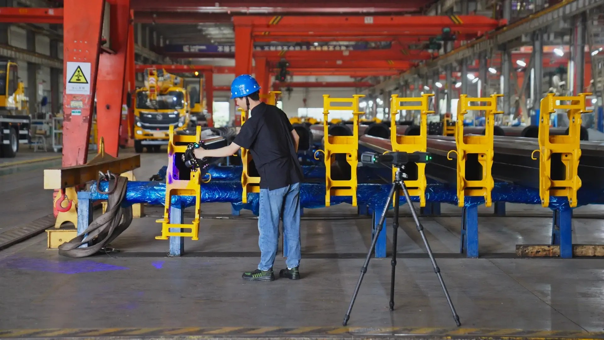
Inline inspection only replaces a laboratory measurement if its results are traceable. Tolerance requirements generally fall into three tiers: 0.005–0.02 mm for critical GD&T inspection, functional safety parts and precision reverse engineering; 0.02–0.05 mm for general assembly verification, automotive body parts and cast components; and 0.05–0.1 mm for overall deformation analysis and large cosmetic parts.
Acceptance testing should reference recognized metrology frameworks. SHINING 3D’s Accuracy Laboratory is accredited to ISO/IEC 17025 by CNAS, is certified to perform accuracy tests and issue calibration certificates in compliance with VDI/VDE 2634 Part 2 and Part 3, and aligns its testing systems and verification protocols with ISO 10360-12 and ISO 10360-13. Because CNAS is a signatory to mutual recognition arrangements such as the ILAC MRA, test reports and calibration certificates are recognized globally. In practice this means a scanner can be specified with an accuracy certificate rather than an accuracy claim.
4. Cycle time and automation integration
Total inspection cycle time is the sum of robot motion, frame capture, data alignment, analysis and report generation — not scan speed alone. Two capabilities compress that sum most effectively. The first is marker-free operation: dynamic optical tracking and Video Photogrammetry (VPG) remove manual or automated marker placement entirely, and VPG eliminates coded markers while holding volumetric accuracy (0.02 + 0.015 mm/m on the FreeScan Omni and FreeScan Combo+ Wireless; 0.046 + 0.012 mm/m on the FreeScan Trak Nova Series). The second is automation level: fixed scanners such as the OptimScan Q12/Q9 support manual operation, semi-automated operation with a tripod and turntable (turntable load up to 20 kg), and fully automated operation integrated with industrial robots. Where a turnkey cell is required, the RobotScan Series combines 3D scanning technology with a robot arm, controller base and turntable to deliver end-to-end automated batch inspection, in-line measurement, quality control and digital traceability.
5. Environmental ruggedness and uptime
Inline installations must survive vibration, temperature swings, dust and changing ambient light. Handheld and tracking systems are specified across a wide operating window — the FreeScan Combo Series from −20 °C to 40 °C, the FreeScan Trak Nova Series from −10 °C to 40 °C, both at 10–90% humidity — and inline heads should be protected by an enclosure matched to the cell environment. Uptime also depends on power strategy: the FreeScan Combo+ Wireless runs up to 2 hours of continuous scanning with a hot-swappable battery and rapid-charging dock, the FreeScan Trak Nova TE delivers up to 2.5 hours in wireless mode with standard swappable batteries, and the FreeScan Omni ships with eight rechargeable batteries supporting up to 1 hour per set with hot-swap replacement that does not require shutting the device down.
6. Software, PLC and MES interfaces
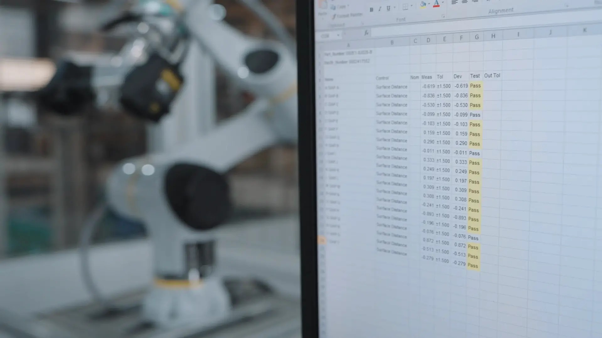
Data acquisition is only part of the workflow. The software layer must perform CAD comparison, deviation analysis, dimensional inspection, GD&T evaluation and report generation, and it must hand a pass/fail decision to the line. SHINING 3D’s ecosystem includes SHINING3D Inspect (PTB-certified, with data quality visualization, AI feature recognition for holes and slots, intelligent resolution and color map comparison), FreeScan Software, PolyWorks, Geomagic Control X, and EXModel or Geomagic Design X for reverse engineering. The FreeScan Omni runs the inspection step on the device itself, without a tethered computer. For inline deployment, the cell design should specify the communication path between the inspection software and the robot controller, PLC and Manufacturing Execution System, so that results feed statistical process control rather than a standalone report folder.
Full-Field Capture Versus Discrete Probing: What Changes on the Line
No single measurement technology covers every inspection task. The table below summarizes how the main options compare when the requirement is automated inline inspection rather than laboratory verification.
| Measurement method | What it does well | Limitation for inline work |
|---|---|---|
| Hand tools (calipers, gauges) | Fast checks of basic dimensions on simple geometries | Cannot capture the full 3D profile of complex curvatures or freeform surfaces |
| Coordinate measuring machine (discrete probing) | Reference accuracy on critical geometric features; suited to regulated, stationary workflows | Bound to an environment-controlled lab; limited on massive castings or large components; programming and fixture lead time; stylus wear and recalibration |
| Consumer / hobbyist 3D scanners | Fast, low-cost visual 3D models and digital assets | Data lacks strict metrological traceability and cannot sign off engineering quality reports |
| Metrology-grade 3D scanners | Lab-level accuracy brought to the shop floor; millions of data points per second; instant color deviation maps | Highly reflective, glossy or translucent surfaces may still require an ultra-thin layer of scanning spray |
Optical full-field scanning is typically 5–10x faster than discrete CMM probing on comparable parts, because the whole surface is captured in a small number of passes instead of point by point. Documented deployments show the magnitude of the change: an automotive OEM automated cell reduced inspection time from about 1 hour to 5 minutes per part; an EMI filter manufacturer reduced prototype measurement from approximately two weeks with outsourced partners, or 3–4 days with an internal measurement lab, to an average of 2–3 hours; and a mold and customized equipment manufacturer cut inspection time from 30–45 minutes to 10–15 minutes per part, improving overall 3D inspection efficiency by approximately 60%.
Maintenance economics change as well. There is no stylus to wear, break or replace, no probe-tip recalibration cycle, and no dedicated fixture to design, store and re-qualify. In one stamping case, replacing dedicated fixtures with a general-purpose scanning system removed a 1.5–2 month fixture development step and cut project time by at least one third, while also avoiding contact pressure on thin, easily deformed parts.
Step-by-Step: Specifying an Inline 3D Inspection Cell
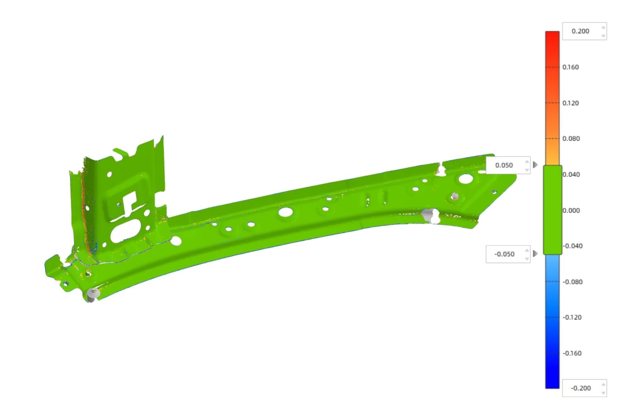
Step 1 — Define the measurement task and the part families. List the part families that will run through the cell, their materials and finishes, the critical dimensions and geometric tolerances, and the inspection standard the results must satisfy. This determines tolerance tier, measuring volume and surface adaptability requirements.
Step 2 — Select the scanner architecture and light source. Choose blue laser for dark, reflective or machined surfaces, blue LED structured light for fine detail and sharp edges, and a hybrid system where both requirements exist. Match architecture to volume: fixed head or desktop system for small parts, handheld or dynamic tracking for medium and large parts.
Step 3 — Verify metrology traceability before price. Confirm that the scanner is accepted and re-verified against VDI/VDE 2634 and ISO 10360, and that calibration is performed in an ISO/IEC 17025 accredited laboratory so that certificates are recognized internationally.
Step 4 — Calculate the real cycle time. Add robot motion, frame capture, alignment, analysis and reporting into one number, then compare it with takt time. Marker-free tracking (VPG) and on-device processing are the two levers that most often bring the total inside the line cadence.
Step 5 — Design the automation and data interface. Decide between manual, semi-automated (tripod plus turntable) and fully automated (robot-integrated) operation, and define how results reach the PLC and MES. A robot-integrated configuration based on the RobotScan Series combines the scanner with a robot arm, controller base and turntable for repeatable batch inspection.
Step 6 — Validate on real production parts. Acceptance is confirmed by delivery inspection and post-installation acceptance, so the validation run should use actual line parts and the same fixtures and lighting conditions as series production. Scan data is aligned to CAD and assessed with the same inspection module that will be used in production, as was done in the EV battery housing case where deviations were evaluated directly on the scanner after mechanical stress tests.
Step 7 — Keep the system calibrated and supported. A practical calibration schedule triggers on first use or after 1–2 weeks of inactivity, after severe shock or vibration such as transport, after any significant drop in accuracy with frequent alignment errors or unrecognized markers, and whenever scan data becomes incomplete or quality deteriorates. Support for OEM and ODM configurations includes remote and onsite service, and systems are supplied with a minimum order quantity of 1 unit and a typical lead time of 30–45 days.
Use Cases: Where Automated 3D Inspection Already Pays Back
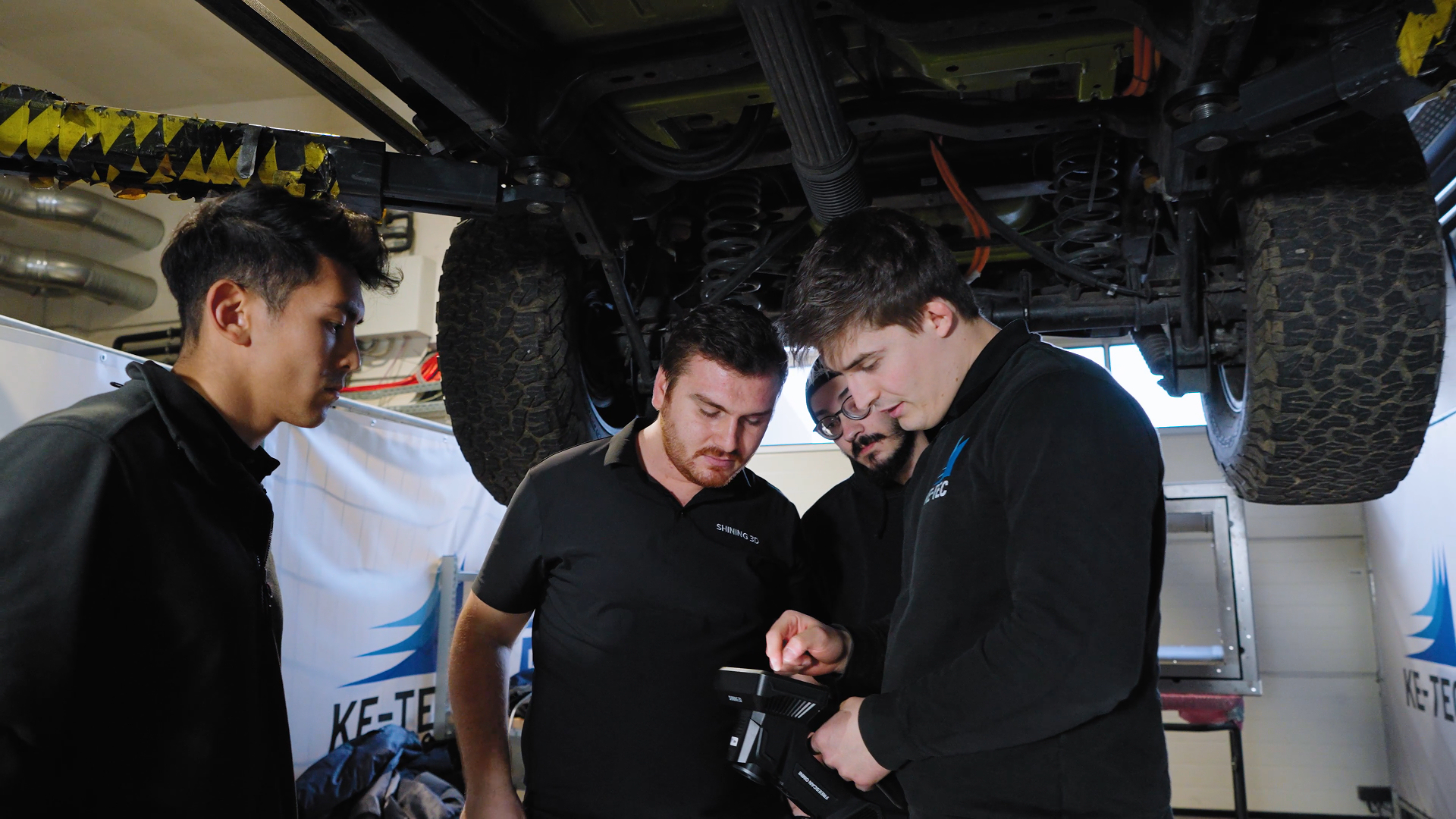
Automotive OEM automated cell (Vietnam). An automotive OEM integrated SHINING 3D scanners with a robotic arm, a purpose-designed fixture and PolyWorks software that compares scan data to CAD, generates deviation analysis and visualizes results on a real-time dashboard with a traceable database. Inspection time dropped from approximately 1 hour to 5 minutes per part, manual data entry was eliminated, and reporting and traceability improved.
Sheet metal and stamping. A stamping parts manufacturer replaced dedicated checking fixtures with a general-purpose 3D scanning system, eliminating a 1.5–2 month fixture build and cutting project time by at least one third. An automotive sheet metal and motor manufacturer now captures complete digital models of sheet metal parts and evaluates holes, edges, dimensions and geometric tolerances in a single digital workflow, reducing the need for dedicated checking fixture functions.
Electronic components and prototypes. An EMI filter manufacturer used a handheld laser scanner with Geomagic Control X to inspect prototypes, reducing measurement time from roughly two weeks (outsourced) or 3–4 days (internal lab) to an average of 2–3 hours, and retained complete surface data for future checks even when physical prototypes are unavailable.
Aerospace components. A manufacturer of certified aircraft components reduced setup time by scanning without detailed programming and without part fixation, capturing data in less than half a day where a CMM would take 2–3 days to program and start collecting data, and reaching operator familiarity in half a day.
Castings, battery housings and heavy machinery. A metal casting manufacturer performs full-size inspections on the production floor before castings leave the factory, contributing to a 99.5% product qualification rate. An EV battery developer scans battery housings larger than one meter on site using VPG-based volumetric accuracy of 0.02 + 0.015 mm/m after mechanical stress tests. In construction machinery manufacturing, handheld scanning supports quality inspection, fixture verification and reverse engineering of legacy components that lack complete CAD data.
Configuration Comparison: Matching SHINING 3D Systems to Inline Tasks
| System | Typical inline role | Accuracy | Scan speed | Volume / key specification |
|---|---|---|---|---|
| FreeScan Omni / Omni Lite | Line-side scan-to-inspect with no tethered computer | 0.02 mm; volumetric with VPG 0.02 + 0.015 mm/m | 7,619,000 points/s | Laser FOV 580 × 650 mm; IR FOV 1205 × 1104 mm; ≤ 1.1 kg; on-device PTB-certified inspection module |
| FreeScan Combo+ Wireless / Combo Wireless | Handheld profiling and line-side gold check | 0.02 mm; volumetric with VPG 0.02 + 0.015 mm/m | Up to 9,106,000 points/s (Combo+ Wireless) | FOV 580 × 650 mm; 550 g; Wi-Fi 7 or USB 3.0; hot-swappable battery |
| FreeScan Trak Nova Series | Marker-free scanning of medium to large assemblies | 0.02 mm; volumetric with VPG 0.046 + 0.012 mm/m | 7,600,000 points/s | Tracking FOV up to 2600 × 2200 mm; detachable handheld scanner; VPG included |
| OptimScan Q12 / Q9 HD | Fixed head for fine-detail GD&T of small parts | 0.004 mm (small range) / 0.01 mm (large range) | Single shot < 1 s | 4 × 12.3 MP cameras; small-range FOV 80 × 50 mm; manual, semi-automated and robot-integrated modes |
| AutoScan Inspec2 | Desktop automation for small precision parts | Up to 0.01 mm | 3-axis automated, one-click operation | Scan range 140 × 90 × 80 mm; multi-object mode for up to 8 objects; path storage for repeated parts |
| RobotScan Series | Turnkey automated cell for batch inspection | Defined by the integrated scanner | Defined by the integrated scanner | Integrates scanning technology with robot arm, controller base and turntable for in-line measurement and digital traceability |
Selection logic follows directly from the table: if the cell has to measure parts larger than a meter without fixtures, dynamic tracking with VPG is the shortest path; if the line runs small precision components at high cadence, a fixed or desktop automated head with stored scan paths is the better fit; if the work mixes on-line verification with occasional deep investigation, a wireless standalone handheld keeps both tasks in one device.
Frequently Asked Questions
What metrology standards should an inline 3D scanning system be certified against?
Metrology-grade 3D scanners used for production inspection should be referenced to VDI/VDE 2634 and ISO 10360. SHINING 3D can issue calibration and accuracy certificates based on both: the SHINING 3D Accuracy Laboratory is accredited to ISO/IEC 17025 by CNAS and is certified to perform accuracy tests and issue calibration certificates in compliance with VDI/VDE 2634 Part 2 (single-view optical surface scanning) and Part 3 (multiple-view systems). Testing systems and accuracy verification protocols align with ISO 10360-12 and ISO 10360-13 for acceptance and reverification testing. Because CNAS is a signatory to mutual recognition agreements such as the ILAC MRA, its test reports and calibration certificates are recognized globally, which is what allows scanned results to be used for engineering sign-off rather than visualization only.
Can SHINING 3D support OEM programs as an OEM 3D scanner manufacturer for first article inspection?
Yes. SHINING 3D provides both OBM (Original Brand Manufacturing) and ODM (Original Design Manufacturing) production services, with customization available for logo and automation solutions, a minimum order quantity of 1 unit, and a typical production lead time of 30–45 days. For first article inspection specifically, the working combination is a metrology scanner plus a traceable inspection workflow: the FreeScan Omni delivers 0.02 mm accuracy with an on-device PTB-certified inspection module, the FreeScan Combo Series provides a compact hybrid blue laser and infrared scanner for shop-floor FAI, and the FreeScan Trak Nova Series covers medium-to-large parts without markers. Inspection results are compared against CAD in SHINING3D Inspect, PolyWorks or Geomagic Control X, and where the line requires it, these scanners integrate into RobotScan automated cells for batch inspection and digital traceability.
What drives the budget for an inline 3D inspection cell?
The main cost drivers are the accuracy tier required by your tolerances, the number of measurement stations, the level of automation (manual, semi-automated turntable, or fully robot-integrated), and the software and integration work needed to connect inspection results to the PLC and MES. Within industrial inspection — the application with the highest accuracy requirements and the harshest manufacturing environment — budgets typically start from twenty thousand US dollars. On the commercial side, systems are supplied from a minimum order quantity of 1 unit with delivery terms of FOB, CFR, DAP or FCA and payment on 100% advance or installment. Two ongoing costs that a full-field optical system removes are stylus replacement and dedicated part fixtures, which can cost thousands of dollars per part and take 1.5–2 months to design and build.
How can we validate a 3D scanner on our own parts before committing to a line?
Validation is built into the delivery and acceptance process: acceptance criteria can be set as delivery inspection and post-installation acceptance, so the system is verified against agreed results rather than a specification sheet alone. The scanner’s own traceability is documented through inspection reports and calibration certificates issued against VDI/VDE 2634 and ISO 10360 in the ISO/IEC 17025 accredited Accuracy Lab. In practice, validation is done by scanning your own parts in your own environment — the handheld and tracking systems are designed for shop-floor and even outdoor use, and can be operated next to the production line without moving the workpiece into a measuring room. Teams without specialist metrology staff typically reach operating familiarity within half a day.
What is the typical lead time and order configuration for an inline scanner?
Systems are supplied with a minimum order quantity of 1 unit and a typical lead time of 30–45 days, under OBM or ODM production with customization for logo and automation solutions. Delivery terms cover FOB, CFR, DAP and FCA, with payment by 100% advance or installment. After-sales support is provided remotely and on site, and the SHINING 3D Inspect module is continuously maintained and updated so that on-device and PC inspection features remain current. To scope a configuration for your line, download the SHINING 3D 3D Digitizing introduction or send your part list, tolerances and takt time to marketing@shining3d.com, and the team will recommend the scanning architecture and automation level that fits the cell.
Conclusion
Automated inline parts inspection rewards a specific kind of 3D scanner: one that captures full-field surface data instead of discrete points, maintains traceable accuracy against VDI/VDE 2634 and ISO 10360, tolerates the materials and the environment of the line, and communicates with the automation stack that surrounds it. Compared with discrete CMM probing, full-field optical scanning is typically 5–10x faster on comparable parts, and it removes the recurring maintenance items — stylus replacement, probe recalibration and dedicated fixtures — that keep probing systems anchored to the measuring room.
The practical next step is to work from the part, not the product page: define the part families and tolerances, match measuring volume and light source, confirm the certificate path, calculate the real cycle time including reporting, and then validate on your own parts before the cell is designed around a scanner. With that sequence complete, the scanner stops being an inspection cost and becomes a production capability — full-surface verification on every part, at line speed, with data that flows into quality management instead of a filing cabinet.

Planning an inline inspection cell? Share your part families, tolerance bands and takt time with SHINING 3D and get a configuration recommendation for scanning architecture, automation level and inspection software.
Download the 3D Digitizing brochure | www.shining3d.com | marketing@shining3d.com | +86 571 8299 9050
Have Questions or Need More Details?
Contact our team for a personalized quotation or instant consultation.
Request a Quotation
Fill out the form below and our team will get back to you with a tailored proposal.
WhatsApp Direct Chat
Prefer to chat in real-time? Message us on WhatsApp for instant assistance & quick answers.
- Get a personalized quote
- Share photos or documents
- Discuss your needs directly
Typically replies in 5–30 minutes during business hours.