
FreeScan UE Pro2 vs. CMM for Quality Control: A Head-to-Head Decision Guide
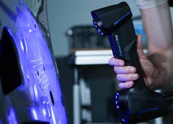
A coordinate measuring machine and the SHINING 3D FreeScan UE Pro2 rarely answer the same inspection question. The CMM answers what is the exact value of this defined feature. A handheld 3D scanner answers how does this entire surface deviate from nominal, and can I know that while the part is still standing on the shop floor.
That difference produces a short, usable decision rule. Give the CMM the features where a single contact-measured number is the deliverable and must survive an audit. Give 3D scanning the work where complete surface coverage, portability, or iteration speed decides whether inspection happens at all. Most quality departments that end up running both do not pick a winner — they split the inspection plan.
This guide works through that split at the level of an actual inspection plan: how each method builds a measurement, where the two diverge on setup, fixturing, coverage, environment and traceability, which tasks fit which method, and what to verify before committing budget.
The Inspection Problem That Sits Behind the Purchase
A quality team does not usually start shopping for a 3D scanner for quality control because a CMM is inaccurate. It starts because inspection has become the slowest step in a loop that needs to be fast. Three patterns recur in documented industrial cases.
Dedicated gauging takes months to build. A stamping parts manufacturer described custom checking fixtures that take 1.5 to 2 months to design and build, at a cost of thousands of dollars per part, with complex parts sometimes requiring two separate fixtures. During that waiting period the parts exist but cannot be formally inspected.
Programming and fixturing consume the calendar. In a documented aerospace PMA component case, the same part required roughly 2–3 days of CMM programming before data collection could begin, and in some cases multiple fixtures that took up to three days to design and manufacture. The same team reported capturing the part's data with a handheld scanner in under half a day.
Key-point checks miss what full-field data catches. Probing a set of defined points verifies those points. It does not describe the surface between them, which is where warpage, springback and shape deformation tend to appear. This is the gap that full-field dimensional inspection was developed to close.
None of those three problems is an accuracy problem. All three are throughput and coverage problems, and they are the reason a handheld route gets onto the shortlist at all.
How Each Method Builds a Measurement
Contact measurement: defined features, one probe point at a time
A CMM drives a probe into physical contact with the part and records the coordinates of each touched point. The measurement path is written in advance, which means the inspection plan is effectively fixed before the part is mounted. Everything the program covers gets measured to a high and well-understood level of confidence; everything the program does not cover does not get measured.
That trade is not a weakness — it is the reason CMM data carries the authority it does for critical fits, gauge work and contractual sign-off. A defined feature, measured by contact, under a fixed program, in a controlled room, produces a number that is difficult to argue with.
Optical measurement: the surface, in one acquisition
Handheld laser scanning works on triangulation. A laser line or pattern is projected onto the object, cameras observe how that pattern deforms across the surface, and software reconstructs the three-dimensional position of the points it sees. Structured-light systems follow the same logic with a projected fringe pattern rather than a laser line. Because the sensor captures an area rather than a point, the output is a dense point cloud describing the whole visible surface.
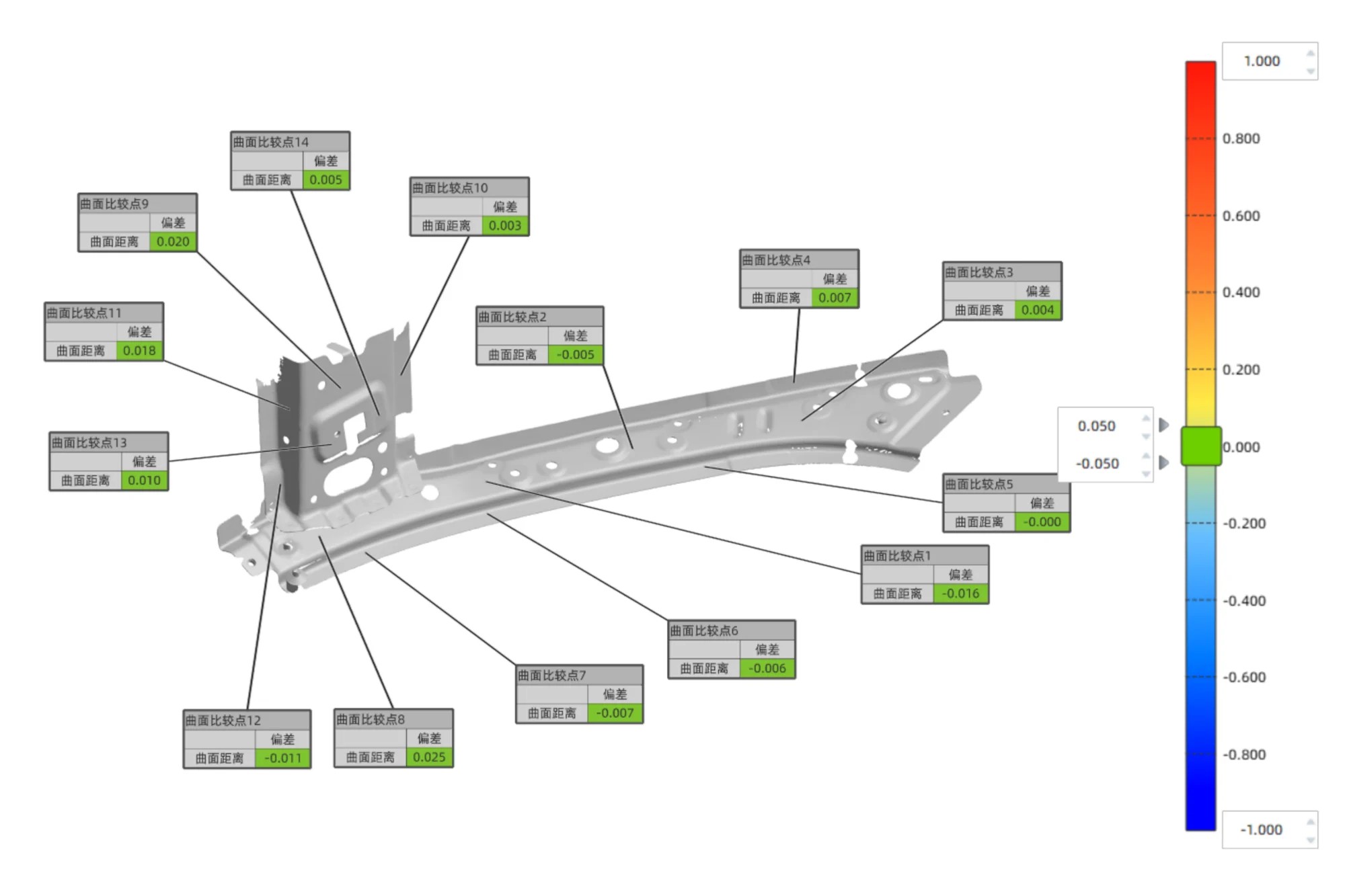
That changes what inspection means. Instead of deciding in advance which points matter, the operator captures the geometry and decides afterwards which dimensions, sections, colour maps and GD&T characteristics to evaluate. The decision moves from before the measurement to after it.
Why the data type drives everything downstream
Two consequences follow, and they explain most of the differences in the sections below.
- Re-evaluation is cheap on full-field data. If a customer asks for an additional cross-section or a flatness value two days after the report was issued, the answer usually comes from re-processing existing scan data rather than recalling and re-measuring the part.
- Full-field data is harder to compress into a single verdict. A colour map showing deviation across a surface requires interpretation and a defined tolerance band before it means anything. A probe measurement returns a number against a tolerance. Both are legitimate; they serve different reporting cultures.

Five Points Where the Two Methods Diverge on a Real Inspection Plan
1. Setup and programming time
This is usually the first difference a production engineer notices. A CMM program is an engineering asset: it has to be written, verified and maintained. For a one-off or a low-volume part, that engineering effort can exceed the measurement time by a wide margin.
The documented aerospace PMA case is instructive because it puts numbers on the gap. For the same part, CMM programming consumed roughly 2–3 days before data collection started; the handheld scanner required connecting power and starting acquisition, with data captured in under half a day. The scanner in that case was a FreeScan Combo+, not a FreeScan UE Pro2, and the figure describes one aerospace component workflow rather than a universal rule. What generalises is the mechanism: program-dependent methods front-load effort, scan-based methods back-load analysis.
2. Fixturing
A CMM needs the part held in a known, stable attitude with the probed features reachable. On awkward geometry that can mean purpose-built fixtures, which the same aerospace case put at up to three days of design and manufacture. A handheld scanner can be walked around the part, and the part can be flipped or re-oriented mid-scan, which removes much of that constraint.
Do not read this as "no preparation". Handheld scanning still needs stable support, a defined alignment strategy and, on some geometries, surface markers or a photogrammetry reference frame. What it removes is the part-specific fixture, not the discipline.
3. Coverage and feature access
Full-field coverage is the strongest argument for the scanning route, and it becomes decisive on thin or compliant parts. A stamping manufacturer noted that conventional checking fixtures use probes or gauges that physically touch the part, which is a risk on thin, easily deformed sheet metal. Non-contact capture records the geometry as it sits, without measurement pressure influencing the result.
The advantage reverses at internal features. Deep holes, blind pockets and narrow internal cavities are exactly where a probe does well and a line of sight does not. SHINING 3D's own selection guidance addresses this directly: where geometry puts features out of optical reach, pairing the scanning system with a portable probe lets the same workflow touch and capture those areas rather than skipping them. A realistic inspection plan treats internal features as a separate line item instead of assuming the scanner covers everything.
4. Environment and part mobility
A CMM is typically a fixed asset in a temperature-controlled metrology room. That is the right environment for the accuracy it delivers, and it also means the part has to travel to the machine. Handheld scanning inverts this: the instrument travels to the part.
Documented cases show what that looks like in practice. A mining and heavy-industry service team scanned a multi-stage slurry pump volute at its installation site rather than dismantling and transporting it. A construction machinery manufacturer verified production fixtures on the shop floor with minimal disruption to manufacturing. An EV battery developer scanned housings larger than one metre directly after mechanical stress testing, without a fixed scanning station.
Volumetric accuracy is the specification that governs how well any of this holds up as part size grows. It describes measurement accuracy across the whole scanning volume rather than at a single point, so error accumulates with distance. On handheld systems this is commonly expressed as a base term plus a per-metre term. SHINING 3D's FreeScan Omni, for example, is specified at 0.02 + 0.015 mm/m with integrated video photogrammetry, and FreeScan Trak Nova at 0.046 mm + 0.012 mm/m with VPG. Those are model-specific figures; the principle — always read the per-metre term against your largest workpiece — applies to any scanner you evaluate.
5. Traceability and reporting
Both routes can be traceable, but the evidence chain looks different. CMM traceability runs through calibrated artefacts and a verified measurement program. Scanner traceability runs through acceptance testing against recognised standards, calibration certificates and, increasingly, an accredited calibration laboratory.
On that last point, the operative standards for optical systems are VDI/VDE 2634 and ISO 10360, and the laboratory performing the verification should itself operate to ISO/IEC 17025. SHINING 3D maintains an ISO/IEC 17025 accredited accuracy laboratory and states that its scanners are calibrated using certified artefacts or calibration panels traceable to metrology standards, with inspection reports and calibration certificates issued against VDI/VDE 2634 and ISO 10360, subject to the actual certificates issued.
What the certificate does not settle is whether a customer or auditor accepts optical measurement for a given characteristic. That is a contractual and quality-system question, and it should be answered before the equipment decision, not after.
What the Handheld Route Looks Like in Practice
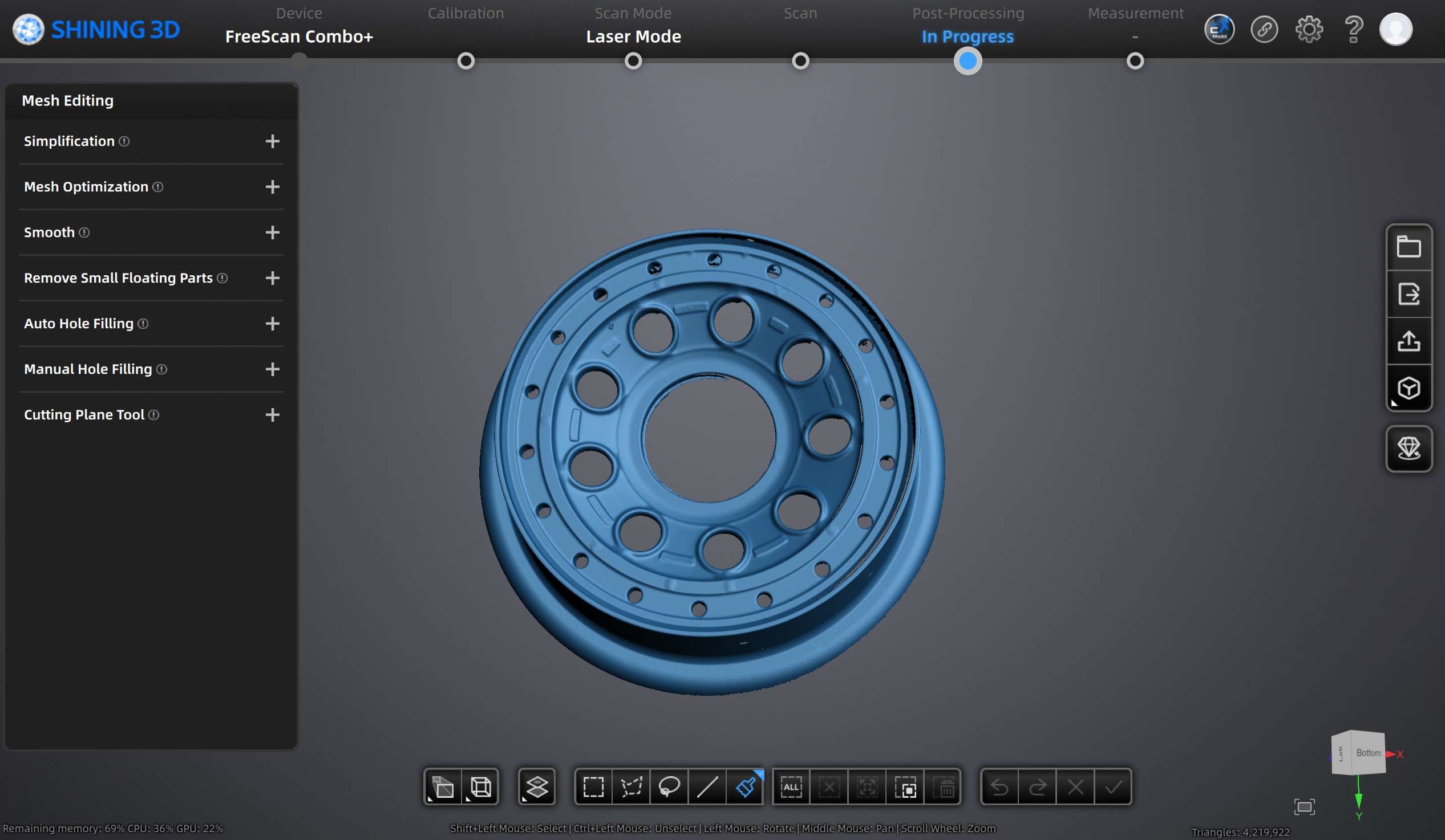
A handheld scanning workflow has five stages, and the scanner only owns the first one.
- Acquisition. The operator sweeps the part, capturing surface data. Scan speed and field of view determine how long this takes; current SHINING 3D metrology handhelds specify 7.6 million points per second on FreeScan Trak Nova and FreeScan Omni, and up to 9.1 million points per second on FreeScan Combo+ Wireless.
- Alignment. Scan data is registered to the CAD coordinate system by best-fit, by datum features, or by reference points. This step decides whether the deviation numbers mean anything.
- Comparison. Scanned geometry is compared against nominal, producing colour deviation maps, cross-sections and dimensional checks.
- GD&T evaluation. Form, orientation, location and profile characteristics are evaluated on the same dataset. This is what makes a 3D scanner for GD&T workable on parts where a dozen characteristics share one surface.
- Reporting. Results are compiled into an inspection report. SHINING 3D supplies SHINING3D Inspect, a PTB-certified inspection module, alongside compatibility with PolyWorks, Geomagic Control X and the FreeScan software environment.
Two capability notes matter for the material side of the decision. Blue laser sources are specified by SHINING 3D as having strong adaptability to black and reflective surfaces, which reduces reliance on scanning spray — the preparation step that most often erodes the time advantage of optical measurement. And on the FreeScan Omni platform, scanning, inspection and reporting can be completed on the device itself without a laptop, which is the configuration that makes on-site and shopfloor inspection practical rather than theoretical.
Side-by-Side Comparison
| Decision dimension | CMM (contact) | Handheld 3D scanning (FreeScan UE Pro2 route) |
|---|---|---|
| Primary data produced | Discrete probed points on programmed features | Dense point cloud covering the visible surface |
| Typical deliverable | Verified dimensions and tolerances on defined features | Full-field deviation map, sections, GD&T across a surface |
| Setup effort | Measurement program written and verified before acquisition | Acquisition first, evaluation configured afterwards |
| Fixturing | Part held in a known attitude; purpose-built fixtures common on complex parts | Stable support usually sufficient; part can be re-oriented during scanning |
| Surface coverage | Limited to programmed features | Full visible surface, including freeform and thin-wall geometry |
| Deep holes and internal cavities | Direct contact measurement | Line-of-sight limited; probe pairing recommended for out-of-reach features |
| Part mobility | Part travels to a fixed machine | Instrument travels to the part; wireless options available across the line |
| Environment | Typically a controlled metrology room | Shop floor, test cell and field use documented in industrial cases |
| Traceability route | Calibrated artefacts plus verified program | VDI/VDE 2634 and ISO 10360 acceptance testing; ISO/IEC 17025 accredited calibration laboratory |
| Repeatability on identical parts | High, program-driven | Depends on alignment strategy, fixturing and operator consistency |
| Strongest fit | Critical fits, gauge work, contractual sign-off, internal features | First article inspection, freeform surfaces, large or immovable parts, low-volume high-mix work |
| Where it is weaker | Throughput on one-off parts; coverage between probed points | Sub-micron work; features without optical access; environments with no alignment reference |
Task-by-Task Fit: Where Each Method Earns Its Place
First article inspection
First article inspection is the clearest win for scanning when the part is geometrically complex and the report has to cover the whole surface. The aerospace PMA case above is the pattern: a part arrives, the team needs dimensional evidence quickly, and the scanner produces it in half a day instead of after a multi-day programming exercise. Where the drawing defines a small set of critical fits that a customer requires to be contact-measured, keep those on the CMM and scan the rest. A 3D scanner for first article inspection is most defensible as the coverage layer, not as a wholesale replacement.
Sheet metal and stamping
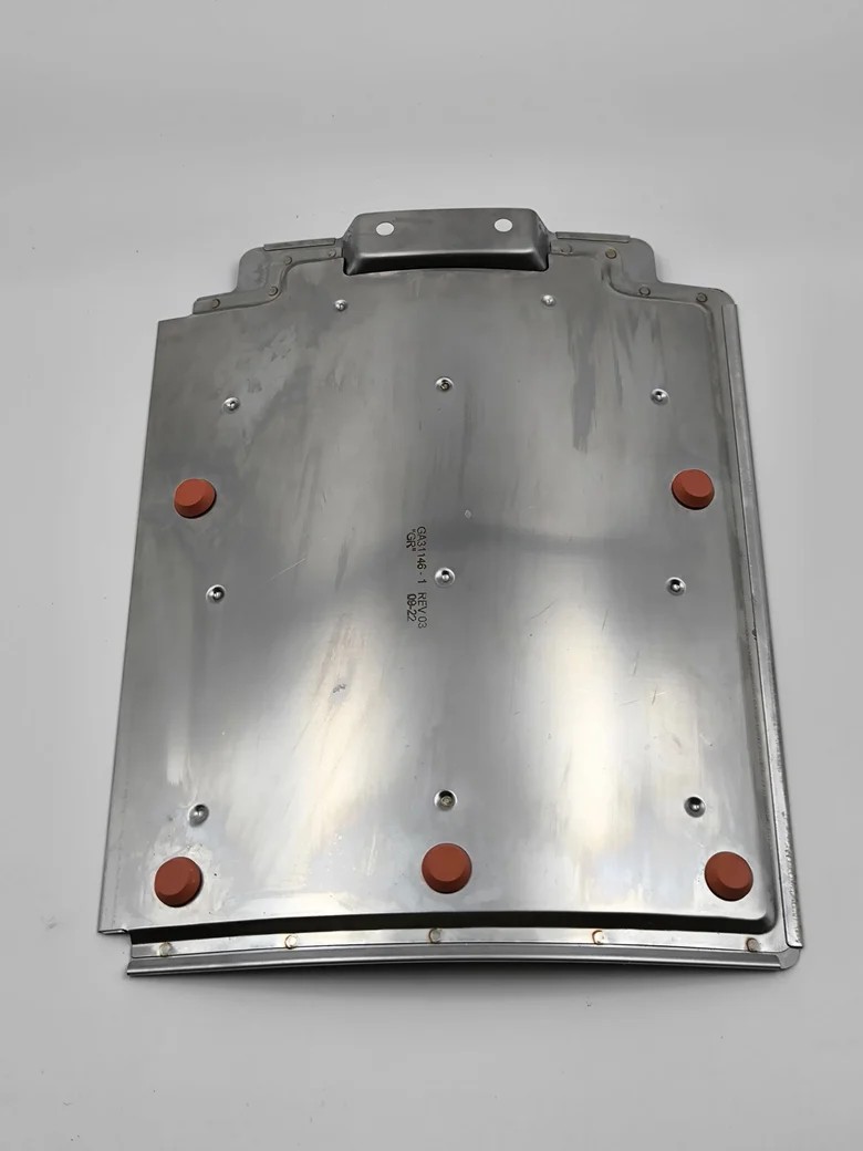
Sheet metal rewards non-contact capture. Thin panels deform under probe pressure, springback shows up as a distributed shape error rather than a point error, and dedicated checking fixtures take weeks to build. Documented users replaced part of their fixture function with a general-purpose scanning system and reported being able to inspect parts immediately rather than waiting for tooling. A 3D scanner for sheet metal inspection also handles hole position, edge trim and profile in one dataset, which is where fixture-based checking gets cumbersome.
Molds, dies and tooling wear
Mold work benefits from the ability to scan the same tool repeatedly and compare across time. Scanning a mold before and after a production run turns wear from an experience-based judgement into a measured comparison, and scanning trial parts against the CAD model shortens the trial cycle. One automotive lighting and precision optics manufacturer reported reducing mold trial cycles from roughly 2–3 weeks to under one week, and using repeated mold scans to quantify wear and plan replacement. A 3D scanner for mold inspection earns its place precisely because the comparison is repeated, not one-off.
Castings and forgings
Casting inspection needs surface coverage and tolerance to dirty, dark and variable surfaces. An aluminum and copper casting manufacturer reported performing full-size inspection before castings leave the factory using a metrology handheld specified at 0.02 mm accuracy, and attributed an improvement in product qualification to 99.5% to that capability. Treat the percentage as that manufacturer's reported result in its own process, not as a general expectation — but the mechanism, catching deviation before machining rather than after, transfers.
Large structures and construction machinery
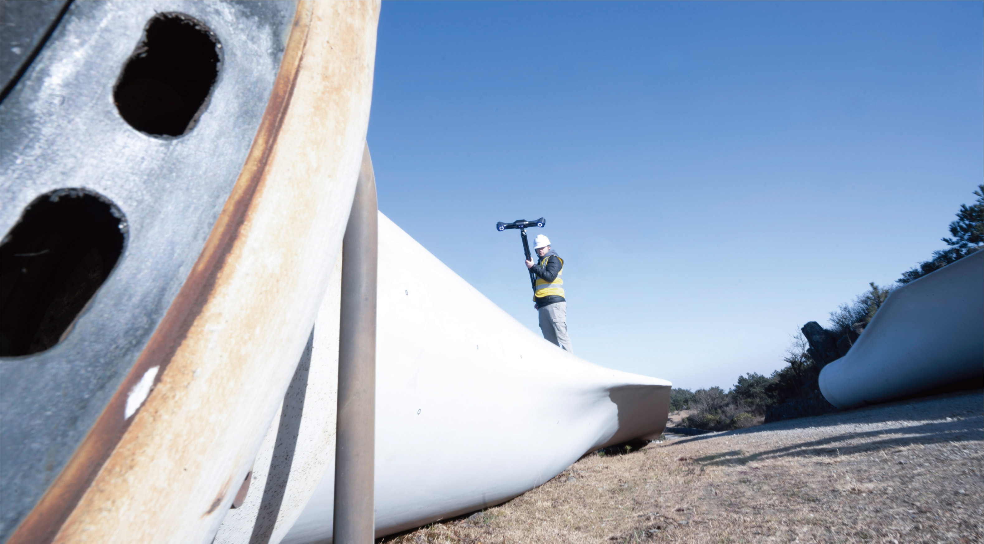
Once workpieces pass roughly 2.5 metres, the constraint shifts from accuracy to reach and volume. A construction machinery manufacturer used handheld scanning for complex exterior panels, on-shop-floor fixture verification and reverse engineering of legacy components without complete CAD. Where the part cannot be moved at all, a 3D scanner for construction machinery manufacturing quality control is often the only practical route, because the alternative is disassembly.
MRO and on-site repair
Maintenance work is where portability stops being a convenience. A hydro turbine inspection and repair workflow, a propeller overhaul shop and a mining service team all describe the same benefit: the measurement happens where the asset is, so the asset does not have to be shipped to a metrology room. A 3D scanner for MRO inspection also builds a digital record of a worn component before repair, which makes post-repair verification a comparison rather than a fresh assessment. One propeller repair shop reported cutting repair assessment time by 20% after integrating scanning into an existing analysis workflow.
Small precision electronic parts
Below a certain feature size, the handheld route stops being the right tool and a fixed optical system takes over. A high-resolution blue-light system such as OptimScan Q12/Q9 HD reaches 0.004 mm in its small range, and a desktop system such as AutoScan Inspec2 automates repeated small-part inspection at 0.01 mm with a 140 × 90 × 80 mm scan range. For 3D scanner for electronic parts quality control work, that class of equipment is usually the correct answer, with the handheld reserved for larger assemblies and field checks.
Automated in-line inspection
When inspection moves into the production line, the decision is no longer scanner versus CMM but which scanning head mounts on which motion platform. SHINING 3D's RobotScan Series combines a metrology scanner with an industrial or collaborative robot and a turntable, with measurable object size up to 500 mm, turntable load up to 20 kg and a robot working radius of 800 mm. A 3D scanner for automated in-line inspection should be specified from the cell requirements outward — cycle time, part family, loading method — rather than from the scanner's headline accuracy inward.
The Hybrid Workflow Most Teams Converge On
After the first year, the pattern that shows up in mixed shops is not a replacement but a division of labour. It usually takes this shape.
- Establish the datum with the authority you already have. Critical fits and reference features are measured on the CMM or against a calibrated artefact, and that result becomes the anchor for the report.
- Capture the full surface optically. The scanner covers the freeform geometry, thin walls, large panels and everything the CMM program does not reach.
- Bring both into one coordinate system. Alignment rules are agreed in advance — datum features, best-fit with defined constraints, or reference points — because this step determines whether the two datasets can be reported together.
- Resolve disputes on the CMM. Where a scan shows a deviation near a tolerance limit on a critical feature, the contact measurement arbitrates. This is a strength of the hybrid model, not an admission about the scanner.
- Report once. One report, two data sources, each identified by method.
The practical friction sits in step three. Alignment conventions, tolerance definitions and file formats have to be settled before the first part, and the inspection software has to accept both data types. SHINING3D Inspect, PolyWorks and Geomagic Control X all operate in this mixed environment; the choice matters less than agreeing the convention once.
What to Verify Before You Commit
Run these checks against your own parts, not against a demonstration sample.
- Acceptance testing and laboratory accreditation. Confirm the standard the accuracy claim is tested against — VDI/VDE 2634 and ISO 10360 are the relevant references for optical systems — and confirm the laboratory performing the test operates to ISO/IEC 17025. Ask for the actual certificate that will ship with your unit.
- Repeatability on your geometry. Scan the same part several times on different days and compare the spread. Repeatability is what makes a 3D inspection scanner for quality assurance usable in a production routine.
- Volumetric accuracy at your largest workpiece size. Read the per-metre term and calculate the error at your maximum dimension rather than at the demonstration part's dimension.
- Material behaviour without spray. Test the actual surfaces you inspect — black anodised, polished, cast, oily. Blue laser sources are specified for strong adaptability to dark and reflective surfaces, but verify on your parts.
- Feature access limits. Identify the deep holes, undercuts and internal cavities in your part family and decide in advance whether they need probe pairing.
- Software and report templates. Confirm the inspection module produces the report format your customers and auditors actually accept.
- Operator learning curve. The aerospace PMA team reported that staff without prior 3D scanning experience needed at most half a day to become familiar with the system. Test this with your own team.
- Support and delivery terms. SHINING 3D lists remote and on-site support, a 30–45 day lead time, a minimum order of one unit and 100% testing before shipment. Confirm these against your procurement requirements.
FAQ
Can a handheld 3D scanner replace a CMM for quality control?
It can replace the CMM on specific tasks, not across an inspection plan. Full-field surface coverage, freeform geometry, thin or compliant parts, large components that cannot be moved, and first-article work where programming lead time dominates are all tasks where a handheld scanner is the practical choice. Critical fits requiring contact measurement, deep internal features without optical access, and characteristics a customer or auditor has specified as contact-measured should stay on the CMM. Most plants end up running both.
What accuracy should I require from a 3D scanner used for first article inspection?
Work backwards from the tightest tolerance on the drawing and require a comfortable margin. SHINING 3D's own selection guidance groups metrology requirements into three bands: roughly 0.005–0.02 mm for functional safety parts and strict GD&T inspection; 0.02–0.05 mm for assembly verification and structural analysis; and 0.05–0.1 mm for overall deformation and large cosmetic parts. Current metrology handhelds in the SHINING 3D line — FreeScan Combo, FreeScan Omni and FreeScan Trak Nova — are specified at 0.02 mm, while the wide-field FreeScan UE Nova is specified at 0.072 mm. FreeScan UE Pro2 figures should be read from its own specification sheet before a tolerance decision is made.
Does 3D scanning remove the need for inspection fixtures?
It removes the need for part-specific checking fixtures in many cases, not all preparation. A documented stamping case replaced custom fixtures that took 1.5–2 months to design and build with a general-purpose scanning system, and cut project time by at least one third. A documented aerospace case removed fixtures that had taken up to three days to design and manufacture. What remains is stable support, a defined alignment strategy, and marker or photogrammetry references where the geometry demands them.
How is a 3D scanner's accuracy verified and traced?
Through acceptance testing against a recognised standard, plus a calibration certificate tied to traceable artefacts. For optical systems the relevant references are VDI/VDE 2634 and ISO 10360, and the calibration should be performed in a laboratory operating to ISO/IEC 17025. SHINING 3D states that its scanners are calibrated using certified artefacts or calibration panels traceable to metrology standards, tested in its ISO/IEC 17025 accredited accuracy laboratory, with reports and certificates issued subject to the actual certificates. On some systems a validated scale bar combined with video photogrammetry is used to verify reference markers in real time and improve global accuracy on large objects.
Which inspection tasks should stay on the CMM, and where do I start if I need a scanner for first article inspection?
Keep on the CMM: critical mating dimensions, gauge and master work, features a customer contractually requires to be contact-measured, and deep internal geometry without optical line of sight. Start the scanning evaluation with your three most time-consuming first-article parts and one large part that currently has to be moved to a metrology room — those four datasets will tell you more than any specification table. SHINING 3D publishes its full digitizing portfolio and metrology product range in the company's 3D digitizing introduction, and the team can review a specific part family, tolerance band and inspection volume against the appropriate handheld, tracking or fixed configuration.
Conclusion
The comparison between FreeScan UE Pro2 and a CMM settles quickly once the question changes from which is more accurate to which inspection task is this. A CMM is the stronger instrument for a defined feature that must be contact-measured and defended. A handheld scanner is the stronger instrument for a surface that has to be described completely, on a part that is large, thin, immovable, or needed before the fixture could possibly be built.
What makes the scanning route viable for quality control is not a single specification but the combination: metrology-grade accuracy class across the SHINING 3D handheld line, acceptance testing against VDI/VDE 2634 and ISO 10360 in an ISO/IEC 17025 accredited laboratory, blue laser adaptability that avoids spray on dark and reflective surfaces, wireless and in some configurations fully standalone operation, and an inspection software layer that produces reportable results. What makes it trustworthy in a regulated environment is the discipline around it — a defined alignment convention, a documented tolerance band, a mixed report that identifies which method produced which number, and a CMM available to arbitrate the critical cases.
Teams that treat the two as competitors usually end up with one method, a backlog, and an argument. Teams that treat them as two lines on the same inspection plan usually end up with faster first articles, better coverage and a CMM that is no longer the bottleneck.

Next step. If you are weighing a handheld 3D scanner for quality control against an existing CMM workflow, send SHINING 3D a representative part and its inspection drawing. The team can advise on configuration, acceptance testing and the alignment convention that lets scan data and CMM data sit in the same report. Product and capability details are in the 3D digitizing introduction, and the full metrology range is listed at shining3d.com.
Have Questions or Need More Details?
Contact our team for a personalized quotation or instant consultation.
Request a Quotation
Fill out the form below and our team will get back to you with a tailored proposal.
WhatsApp Direct Chat
Prefer to chat in real-time? Message us on WhatsApp for instant assistance & quick answers.
- Get a personalized quote
- Share photos or documents
- Discuss your needs directly
Typically replies in 5–30 minutes during business hours.