
FreeScan UE Pro2 vs. CMM for Quality Control: A Head-to-Head Decision Guide
Short answer. A CMM and a handheld metrology 3D scanner such as the FreeScan UE Pro2 cover different halves of quality control. Use handheld 3D scanning as the primary tool when the workload is dominated by freeform surfaces, sheet metal, tooling and molds, castings, or parts that are large, already installed, or needed quickly on the shop floor. Keep the CMM primary when tolerances sit at or below the scanner's verified accuracy, when features have no optical line of sight, or when the drawing and the audit trail call for tactile measurement. Many programs run both: scanning for full-field screening and deviation maps, CMM for a short list of critical features.
This guide compares the two routes on the criteria that actually decide a quality-control purchase: the data each method produces, setup and fixturing, feature fit, traceability documents, throughput and cost drivers. It ends with a screening framework you can run against your own part family before committing budget.
How the figures are used. Numbers quoted for SHINING 3D handheld scanners belong to the named model: 0.02 mm on FreeScan Combo, FreeScan Combo+ Wireless, FreeScan Omni and FreeScan Trak Nova, and 0.072 mm on FreeScan UE Nova. The FreeScan UE Pro2 has its own datasheet, calibration certificate and acceptance test report, and those documents, not values borrowed from a sibling model, are what an auditor asks to see. CMM entries describe general contact-metrology practice rather than a specific machine specification.
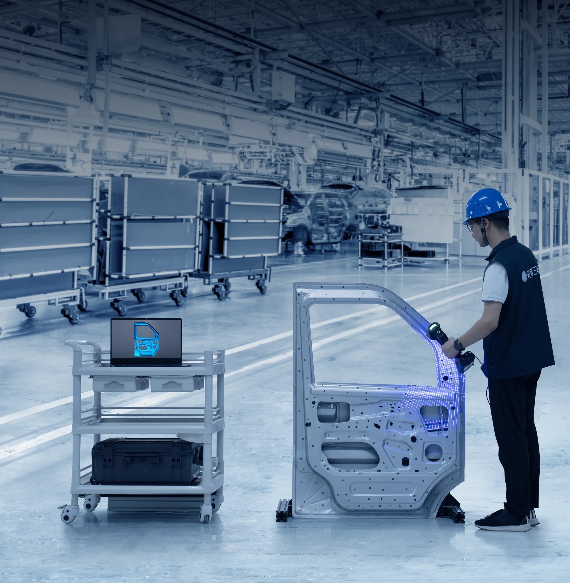
Shop-floor scanning of tooling: the part is measured where it sits, without a metrology-room queue.
Why this comparison keeps appearing on quality-control agendas
The pressure behind the question is sampling. A CMM measures the points its program tells it to measure. That is exactly right for a drawing full of toleranced features, and exactly wrong for a stamped panel, a worn die or a freeform casting, where the surface can deviate between probed points without the report showing it.
Optical scanning inverts the trade-off. One pass captures dense surface data over the visible geometry, and inspection software compares that mesh with the CAD model to produce a colour deviation map, GD&T evaluation and a report. Nothing is missed because it was not programmed; what is missed is whatever the light cannot see.
The industrial background matters here. 3D inspection has moved out of specialist laboratories into routine quality toolkits in automotive, aerospace, consumer electronics and mold making, alongside tactile metrology rather than instead of it. A CMM remains the established reference for tightly toleranced prismatic features, and its programs and fixtures are often part of a validated process that nobody wants to disturb before an audit. The commercial question is therefore workload allocation, not a winner-takes-all verdict.
How a CMM measures, and what that means for the report
A CMM measures by touching. A probe travels a programmed path to discrete points on the part; the machine records each point, compensates for probe radius, and evaluates features such as diameter, position, flatness or profile against datums established by an alignment routine. The output is a defined set of measured features with a stated uncertainty under stated conditions.
Three planning consequences follow. Measurement time scales with the number and complexity of programmed features rather than with part complexity. The part must be fixtured and aligned, and awkward geometries may need several fixtures. And what is not programmed is not measured. None of that is a defect: it is what makes a CMM dependable for a prismatic part with thirty toleranced features. It does explain why CMM queues build during first article inspection, and why a part can pass its key-point check and still show a surface deviation during assembly.
How the FreeScan UE Pro2 measures, and what that changes
The FreeScan UE Pro2 is the handheld metrology scanner in this comparison, so the relevant working principle is optical triangulation: the operator moves the device over the part and the system reconstructs surface geometry from the reflected light. Three optical techniques dominate this branch of metrology.
- Laser line. Laser beams are projected as lines across the surface and sensors read the reflected signal, using known angles and distances to construct the 3D model. It suits industrial inspection and copes well with dark or reflective surfaces.
- Structured light (fringe). A projector casts a known pattern onto the part, cameras capture how the pattern deforms across the surface, and software computes the 3D position of points. It is strong on fine texture, complex geometry and small detail; strong ambient light can disturb the projected pattern.
- Photogrammetry, including VPG. Cameras measure shape, size and spatial position from images. Video photogrammetry replaces hundreds of static images with continuous capture and is used to control global accuracy across large measurement volumes.
For a QC team, three practical consequences follow: the part can usually be scanned where it sits, dense data arrives in a single pass, and the report is a full-field comparison rather than a list of probed points. Two qualifiers belong beside that. Wireless transmission, where the model provides it, carries data only and does not change accuracy. And surface preparation remains a variable: blue laser light handles many dark and reflective parts without spray, and marker-free operation is documented on several models, although markers may still be recommended on very large surfaces to hold accuracy.
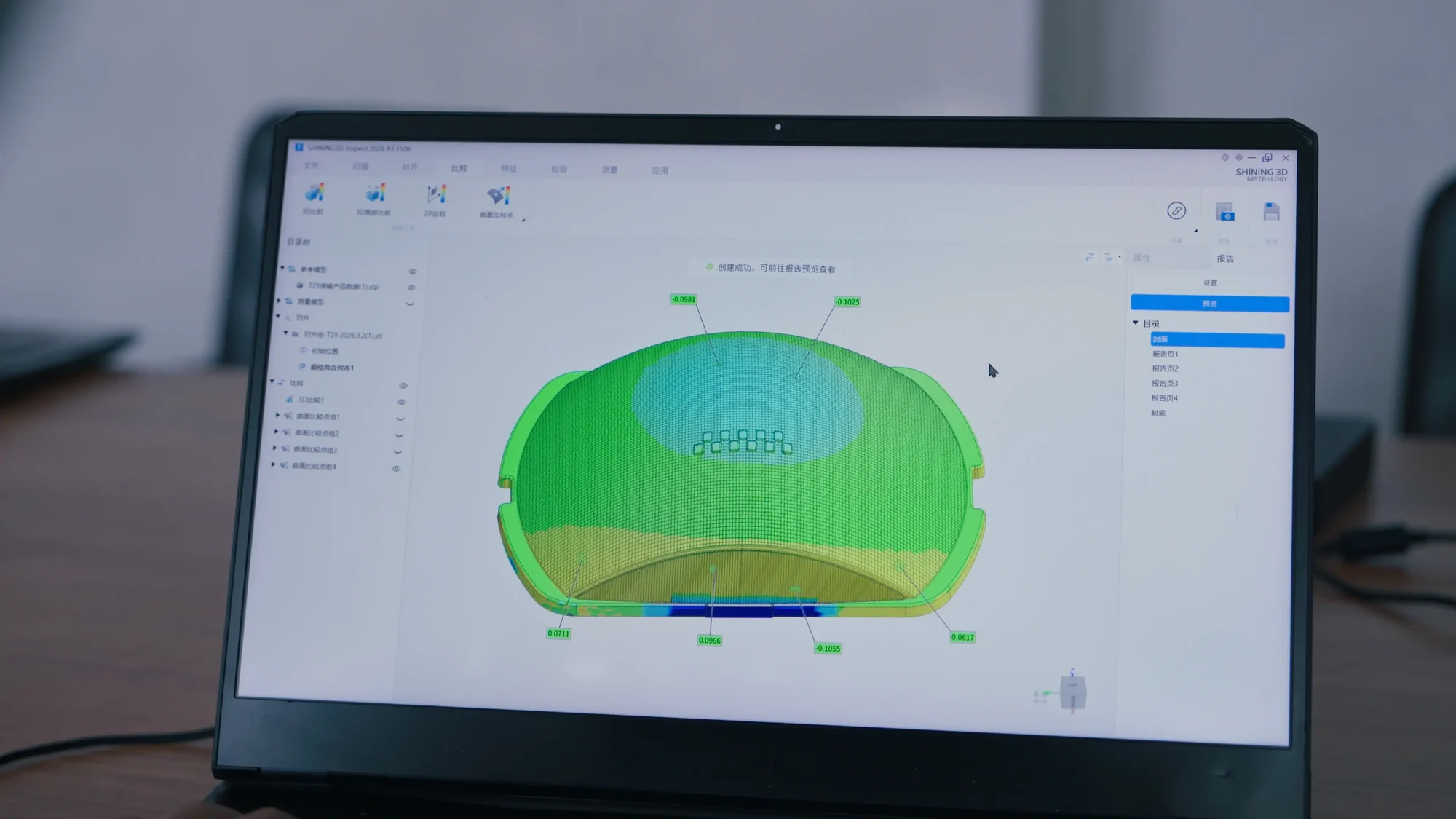
Full-field inspection output: the whole scanned surface is compared with CAD, so deviations are localised everywhere rather than only at programmed points.
Head-to-head comparison table
| Criterion | Handheld optical scanning (FreeScan UE Pro2 route) | CMM (contact metrology) |
|---|---|---|
| Measurement principle | Non-contact optical triangulation: laser line, structured light, photogrammetry | Contact probing of discrete points along a programmed path |
| Data produced | Dense point cloud or mesh of the visible surface | Measured points and evaluated features along the program |
| Fixturing | Often none; a documented aerospace case scanned parts without jigs or fixtures | Fixturing and alignment normally required; the same case cites fixtures taking up to three days to design and build |
| Programming and setup | Scan-ready after connection; under half a day to first data in the documented case | Part program per component; two to three days to program and start collecting data in the same case |
| Where measurement happens | Shop floor, on site, outdoors; several handheld models documented from -10 to 40 °C and 10–90% RH | Typically a temperature-controlled metrology room |
| Surface and material | Blue laser handles many dark, shiny and reflective surfaces; some geometries still need preparation or markers | Largely insensitive to colour and reflectivity; soft or thin parts can deflect under probing |
| Strongest feature types | Freeform surfaces, form and profile, springback, wear, full-field deviation | Prismatic features, bores, threads, tight tolerances with established datums |
| Traceability documents | VDI/VDE 2634 Part 3 and ISO 10360 acceptance testing in an ISO/IEC 17025 accredited laboratory; calibration certificates | ISO 10360 based specification and calibration; established audit practice |
| Throughput evidence | Documented cases: about one hour reduced to five minutes per part in an automated cell; 30–45 minutes reduced to 10–15 minutes for molds | Depends on program length, feature count and inspection queue |
| Principal risk | Optical access, surface preparation, data volume, operator coverage | Setup bottleneck, fixture cost, deviations between probed points |
Scanner-side entries reflect published specifications and documented cases of the named SHINING 3D models; CMM-side entries describe general practice and should be replaced with your machine's specification and your drawing requirements before any purchase decision.
What the accuracy figures actually mean
Accuracy, precision, resolution and volumetric accuracy are four different statements, and mixing them is the most common error in a scanner-versus-CMM discussion. Accuracy is how closely a measured result matches the true dimension: a 100.00 mm feature reported as 100.02 mm carries 0.02 mm error. Precision, or repeatability, is how consistently the same measurement repeats under unchanged conditions, so a scanner can be highly precise while slightly offset. Resolution is the smallest detail the system can distinguish, and higher resolution does not automatically mean higher accuracy.
Volumetric accuracy is the figure that decides large-part work, because it describes accuracy across the whole measurement volume instead of at a single point. With a specification written as 0.02 mm + 0.015 mm/m, a 2 m part carries a maximum error of 0.02 + (0.015 × 2) = 0.05 mm. Errors accumulate with distance, which is why photogrammetry and VPG are used to hold global accuracy on large components.
Comparing honestly means comparing like with like: a tactile machine's specification and a scanner's VDI/VDE 2634 acceptance value are not the same statement, and neither is a laboratory test the same as performance on a dusty casting in a workshop. Published reference points on the SHINING 3D handheld platform show the spread: FreeScan Combo and FreeScan Combo+ Wireless at 0.02 mm (volumetric 0.02 + 0.033 mm/m, and 0.02 + 0.03 mm/m or 0.02 + 0.015 mm/m with VPG respectively), FreeScan Omni at 0.02 mm with 0.02 + 0.015 mm/m under VPG, FreeScan Trak Nova at 0.02 mm with 0.046 mm + 0.012 mm/m under VPG, and FreeScan UE Nova at 0.072 mm for wide-area work. For the FreeScan UE Pro2, the certificate issued with the unit is the number that counts.
Setup, fixturing and programming: the cost that is not on the datasheet
The biggest day-to-day difference is often preparation, not accuracy. A Thailand-based manufacturer of aircraft PMA components reported that the same part needed two to three days of CMM programming and setup, against less than half a day to start capturing data with a handheld scanner, with no jig or fixture required in the scanner workflow; in some cases CMM inspection required multiple fixtures taking up to three days to design and manufacture. The same team noted that operators without specialist scanning skills needed at most half a day to become familiar with the device. That is one documented case rather than a benchmark for every shop, but the mechanism it describes, program and fixture lead time, is general.
Preparation is also where automation changes the arithmetic. A Vietnamese automotive OEM working with an integrator reduced inspection from about one hour to about five minutes per part by combining a SHINING 3D scanner with a robotic arm, purpose-designed fixtures and PolyWorks software for CAD comparison and reporting. A Thai manufacturer of high-precision molds and custom equipment cut inspection from 30–45 minutes to 10–15 minutes per part. In both cases the gain came from the whole workflow, not from scan speed alone.
Where a CMM is still the right primary tool
An honest comparison has to state where optical scanning stops. A CMM remains the better primary instrument in these situations:
- Tolerance below verified scanner accuracy. If the tightest callout is finer than the scanner's certified accuracy at the relevant volume, the tactile machine keeps that feature.
- No optical line of sight. Deep bores, internal threads, undercuts and hidden faces cannot be scanned optically; adding a portable probe to a tracking system extends reach, but it changes the tool and the workflow.
- Contract or audit language. Where the drawing, the customer or a validated program specifies tactile measurement, plan around it rather than argue with it.
- Surfaces that resist optics. Transparent, mirror-like or extremely dark surfaces can require spray or preparation that production rules out.
- Alignment decisions already solved. Scanned data still depends on judgement: best-fit versus datum alignment, filtering and point selection all change the reported deviation. A CMM program encodes those decisions once; a scanning workflow encodes them in templates and operator practice, which must be controlled if results are to repeat across shifts.
Where handheld 3D scanning is the better primary tool
Scanning earns the primary role where the geometry is freeform, the part is large or immovable, the real question is where the part deviates rather than what one diameter measures, or feedback speed drives the process.
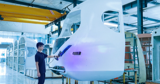
Aerospace first article and MRO work is where full-field capture complements tactile verification.
Documented examples across industries:
- First article inspection of complex parts. Aircraft PMA components were measured without jigs, with data captured in under half a day.
- Tooling, molds and dies. An automotive lighting and precision optics manufacturer cut mold trial cycles from roughly two to three weeks to under one week, and quantified mold wear by comparing scans before and after production instead of relying on experience-based judgement.
- Castings. A metal casting manufacturer performs full-size inspection before shipment and reports product qualification at 99.5% after adopting handheld scanning.
- Sheet metal and stamping. Hole position, springback and die wear are surface questions that suit full-field comparison; a stamping die can be scanned in place to decide whether it needs correction.
- Large and installed equipment. A Chilean engineering firm measured a ball mill on site and evaluated cylindricity where internal micrometers could not reach 180 degrees; an Australian fabricator reduced inspection of a 15-tonne trommel screen from days to hours; an Australian mining service team scans slurry pump volutes in place with a standalone scanner.
- Marine, energy and transport. Aluminium hull scanning quantified welding distortion on an electric sailboat; a German battery test provider scans EV battery housings over one metre long and evaluates deformation on the device; a propeller repair shop cut repair time by 20% after moving assessment to scanning.
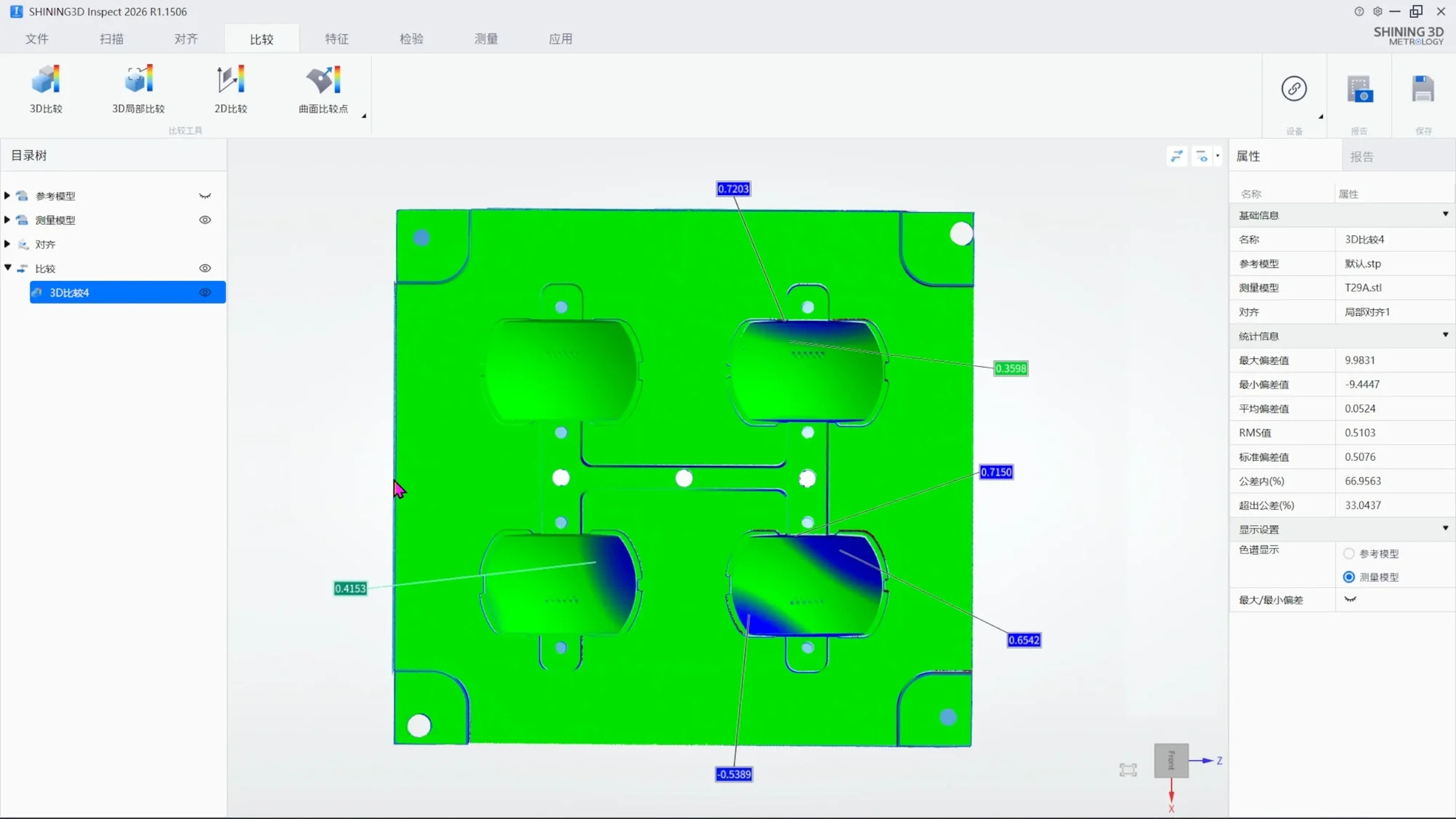
Mold wear made measurable: scans taken before and after production are compared to quantify wear and plan replacement.
Decision framework: seven questions that settle it
Run these against your part family; the answers usually point one way.
- Tolerance against verified accuracy. SHINING 3D's published selection guidance groups requirements as 0.005–0.02 mm for functional safety parts and strict GD&T, 0.02–0.05 mm for assembly verification and structural analysis, and 0.05–0.1 mm for deformation and large cosmetic parts.
- Feature accessibility. Bores, threads and hidden faces favour tactile probing; open surfaces, edges, radii and freeform geometry favour scanning.
- Part size. Small, high-detail parts suit fixed optical systems (OptimScan Q12/Q9 HD reaches 0.004 mm in small range, and AutoScan Inspec2 reaches 0.01 mm on parts up to 140 × 90 × 80 mm), medium parts suit handheld scanning, and multi-metre structures need tracking or wide-area scanning.
- Where the part is. If it cannot travel to a metrology room, scanning wins by default.
- Throughput and queue. Count parts per shift and inspection hours per part, including programming and fixturing.
- Reporting requirement. Confirm the software produces the GD&T evaluation and report format your customer accepts; SHINING3D Inspect is PTB-certified and is complemented by PolyWorks and Geomagic Control X.
- Audit language. If the contract names tactile measurement, design a hybrid workflow rather than a replacement.
What to verify before you commit
On the scanning side, ask for the acceptance test report and calibration certificate, confirm the standards named (VDI/VDE 2634 Part 3 and ISO 10360), and check that testing was performed in an ISO/IEC 17025 accredited laboratory. SHINING 3D operates such a laboratory and states that all calibration and verification procedures are performed there. Ask how the scanner behaves on your surfaces, whether markers are needed on your largest part, and what volumetric accuracy means at your part length.
Then check the unglamorous items that decide whether the tool survives production: minimum order quantity of one unit, stated lead time of 30–45 days, 100% test before shipment, remote and on-site support, and a calibration routine. Calibration is due at first use or after one to two weeks of inactivity, after severe shock or transport, when accuracy drops or markers stop being recognised, and when scan data quality deteriorates. Put that schedule in the maintenance plan rather than in a drawer.
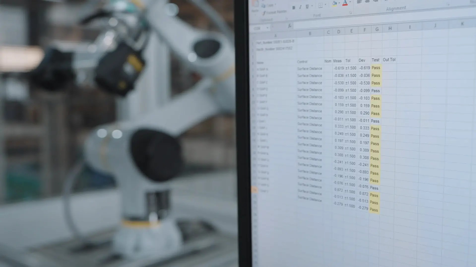
The deliverable an auditor sees: scan data, CAD comparison and a traceable inspection report.
Why SHINING 3D sits on the optical side of this comparison
SHINING 3D (Shining 3D Tech Co., Ltd.), founded in 2004 and headquartered in Hangzhou, develops high-precision 3D vision hardware and software rather than CMMs, which is why the tactile half of this guide stays generic. The company employs 1,367 people including a 533-engineer R&D team, holds more than 330 authorised patents and 230 software copyrights, and exports about 70% of its output to the EU, USA and Asia-Pacific, with subsidiaries in Germany, Spain, the United States and Japan. Its quality infrastructure includes ISO 9001, ISO 14001, ISO 45001 and ISO 13485 management systems, an ISO/IEC 17025 accredited accuracy laboratory, AEO status for supply-chain security, and TISAX and ISO/IEC 27001 for information security.
The range matters to the decision because the right optical tool depends on the part: FreeScan Omni for standalone on-device inspection, FreeScan Combo+ Wireless for cable-free work with VPG, FreeScan Trak Nova for tracking medium-to-large parts without coded markers, FreeScan UE Nova for wide-area work with a field of view up to 2,600 × 2,200 mm, OptimScan Q12/Q9 HD for fixed high-precision small-part inspection, AutoScan Inspec2 for automated desktop inspection, and RobotScan for automated cells. A scanner-versus-CMM decision should be matched to the part, not to the brochure.
FAQ
What standards should a 3D scanner meet before it is used for quality control?
Ask for VDI/VDE 2634 Part 3 and ISO 10360 acceptance testing performed in an ISO/IEC 17025 accredited laboratory, plus a calibration certificate traceable to those standards. The inspection software matters too: SHINING3D Inspect is PTB-certified for GD&T evaluation and reporting. For large parts, request volumetric accuracy with video photogrammetry rather than single-point accuracy; 0.02 + 0.015 mm/m is published for FreeScan Combo+ Wireless and FreeScan Omni. The FreeScan UE Pro2 certificate that ships with the unit is the document your audit will reference.
Can a 3D scanner replace a CMM for first article inspection?
For many first article reports, a handheld scanner supplies the full-field evidence faster, but it does not automatically replace the CMM. A Thailand-based manufacturer of aircraft PMA components reported that the same part needed two to three days of CMM programming and setup, against under half a day to start scanning, and that some CMM inspections required fixtures taking up to three days to build. Keep the CMM for features below the scanner's verified accuracy, for bores and threads without optical access, and wherever the drawing specifies tactile measurement.
How do I evaluate a 3D scanner manufacturer for first article inspection work?
Check four things: certified accuracy and the accredited laboratory behind it; inspection software that produces the GD&T evaluation and report format your customer accepts; documented first article work in your industry, such as aerospace PMA components or automotive tooling; and a calibration and support model that keeps the device in service. SHINING 3D, founded in 2004, operates an ISO/IEC 17025 accredited accuracy laboratory, holds ISO 9001, ISO 14001, ISO 45001 and ISO 13485 certification, and publishes VDI/VDE 2634 and ISO 10360 acceptance testing for its metrology scanners.
Which is better for GD&T: a 3D scanner or a CMM?
Both can evaluate GD&T; they differ in evidence. A CMM measures programmed points and features with tactile certainty, which suits datum-heavy prismatic parts and bores. A scanner measures the whole visible surface and is stronger for form, profile and freeform geometry, where a deviation map shows what point checks miss. Do not assume the two are interchangeable: run one representative part through both and compare the reported values against the drawing before you reallocate any tolerance.
Can a handheld 3D scanner be used for shop floor and on-site inspection?
Yes, and that is often the deciding advantage. Wireless handheld models are documented across -10 to 40 °C and 10–90% RH, and wireless transmission carries data only, so it does not change accuracy. FreeScan Omni is a standalone unit at 1.1 kg or less with a 5.5-inch touchscreen and on-device inspection; FreeScan Combo+ Wireless is a 550 g unit with a hot-swappable battery rated for up to two hours of scanning. Documented on-site work includes slurry pump volutes, ball mills, ship hulls and aircraft structures.
What drives cost in a scanner-versus-CMM decision?
Purchase price is one line among several. Count fixturing, programming labour, floor space in a controlled room, queue time, software seats, calibration and service. SHINING 3D's published selection guidance notes that industrial inspection carries the highest accuracy requirements and that budgets typically start from around twenty thousand US dollars for this class of equipment. Compare total inspection hours per part across a year rather than the invoice alone.
Can we test the scanner on our own parts before deciding?
Yes. A sample scan is the fastest way to settle the comparison. Send one representative part with its CAD model and the GD&T callouts you need verified, and ask for a deviation report plus the FreeScan UE Pro2 datasheet, calibration certificate and acceptance test report. Check the commercial terms at the same time: minimum order quantity is one unit, stated lead time is 30–45 days, and support is available remotely and on site. Contact SHINING 3D through the official website to arrange the sample.
Conclusion
The comparison resolves into a workload question. If your inspection queue is dominated by freeform surfaces, tooling, sheet metal, castings or parts that cannot travel, handheld scanning such as the FreeScan UE Pro2 should carry the primary workload and the CMM becomes the referee for critical features. If your drawings are dominated by tightly toleranced prismatic features inside a controlled room, keep the CMM primary and add scanning where the CMM cannot see. Either way, decide on your own geometry: a sample scan of one representative part, reported against your CAD model and GD&T callouts, answers more than any datasheet comparison.

Arrange a sample scan of your own part before finalising the comparison.
Next step. Send one representative part and its CAD model, and SHINING 3D will scan it and return a deviation and GD&T report so the comparison is made on your geometry. Ask for the FreeScan UE Pro2 datasheet, calibration certificate and acceptance test report at the same time. Minimum order quantity is one unit, stated lead time is 30–45 days, and support is available remotely and on site.
Company: SHINING 3D official website · Brochure: SHINING 3D 3D Digitizing introduction (PDF)
Have Questions or Need More Details?
Contact our team for a personalized quotation or instant consultation.
Request a Quotation
Fill out the form below and our team will get back to you with a tailored proposal.
WhatsApp Direct Chat
Prefer to chat in real-time? Message us on WhatsApp for instant assistance & quick answers.
- Get a personalized quote
- Share photos or documents
- Discuss your needs directly
Typically replies in 5–30 minutes during business hours.