
FreeScan UE Pro2 vs. CMM for Quality Control: A Head-to-Head Decision Guide
FreeScan UE Pro2 and a coordinate measuring machine (CMM) are both quality-control instruments, but they answer different project questions. The handheld 3D scanner fits projects where the deliverable is a complete surface — a small or medium sized sheet metal part, a casting housing, a machined component, a mold insert — captured near the production line and compared with CAD. A CMM fits projects where the deliverable is a defined set of tight-tolerance features, probed one at a time under a controlled metrology routine and reported against the drawing. Quality departments that inspect both freeform geometry and critical mating features usually run both tools, and split the work by what each one has to prove.
This guide takes the comparison down to the level where the decision is actually made: part family, tolerance class, fixture burden, environment, throughput and the report the customer accepts. It does not argue that one technology replaces the other. Product statements come from SHINING 3D's published documentation, and every case reference is labelled as a case rather than generalised into a promise.
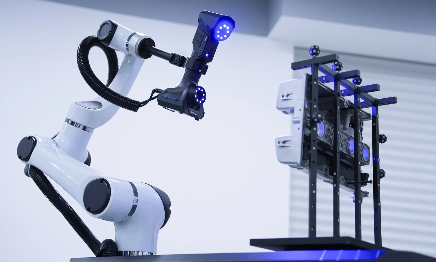
The project question behind the purchase
In practice the choice is rarely "optical versus contact" in the abstract. It is a specific blocked project: a new stamping tool that needs first article inspection before the die is signed off, a mold that has to be measured for wear, a casting supplier whose dimensional report is being disputed, or an incoming lot that cannot wait in the metrology lab queue. Two questions separate the options faster than any specification sheet.
- Does the project need full-surface evidence, or a defined list of features?
- How much work happens before the first data point exists?
CMM inspection concentrates its effort in the second question — programming and holding the part — and returns precise values for the features inside the programme. A 3D scanner for quality control inverts that balance: preparation is short and the data volume per part is much larger, which is an advantage on freeform surfaces and a processing load on simple prismatic parts.
What FreeScan UE Pro2 is, and what the documentation covers
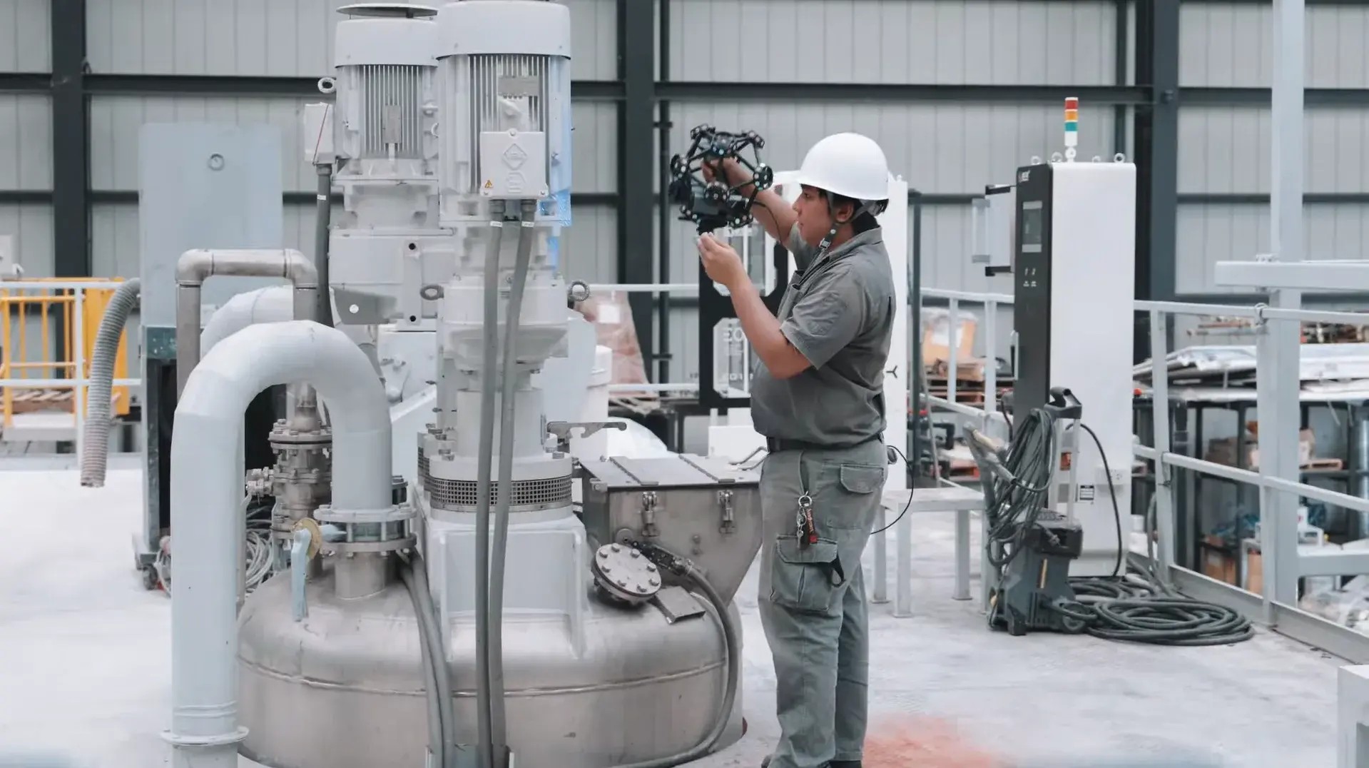
FreeScan UE Pro2 is a handheld metrology 3D scanner in SHINING 3D's metrology range, built on blue laser scanning technology. SHINING 3D documents the scanner, within its RobotScan UE Pro2 configuration, as handheld blue laser scanning technology with strong material adaptability to black, shiny and reflective surfaces, suited to small and medium sized sheet metal parts, casting housings, machining parts and mold components, with wireless and wired connectivity for flexible on-site integration. The RobotScan UE Pro2 configuration pairs that scanner with an industrial or collaborative robot for automated optical measurement.
SHINING 3D (Shining 3D Tech Co., Ltd.) is a 3D vision technology company founded in 2004 and headquartered in Hangzhou, China, with metrology 3D scanners among its main product lines. Calibration and verification for its scanners are carried out in an accuracy laboratory accredited in accordance with ISO/IEC 17025.
One point of discipline for the buyer: the usable tolerance of any 3D scanner depends on the model, on how error accumulates across the working volume, and on whether video photogrammetry supports long parts — not on a single headline number. Read accuracy from the acceptance test documentation issued for the configuration you are quoted, together with the standard it references.
What a CMM contributes that an optical scanner does not
A CMM is a contact instrument. A probe touches the surface at programmed positions, the machine returns coordinates for those points, and the software evaluates dimension, position, form and orientation against the drawing. Three consequences follow from that mechanism:
- Drawing-tied results. Each value is attached to a named feature and a declared datum scheme, which is the format most drawing-based dimensional reports expect.
- Independence from surface optics. Because it does not rely on returning light, colour and reflectivity do not affect the measurement.
- Discrete coverage. Only programmed points are measured. Unmeasured areas are not evidence of conformity, however the part looks on the bench.
Those properties are the reason a CMM remains the reference instrument for critical mating features and for approvals tied to a specific measurement routine.
Setup and fixturing: where the two workflows diverge
In a documented inspection case at an aircraft parts manufacturer in Thailand producing PMA components, the quality team compared its existing CMM routine with handheld 3D scanning on the same parts. It reported that a CMM needed two to three days to create the programme and begin collecting data, while the scanner workflow could start capturing data in less than half a day. Some parts also required multiple fixtures on the CMM, with fixture design and manufacture taking up to three days. The scanner needed no jig or fixture design; the operator could change the scanner angle or turn the part over.
Fixture burden is not a defect of CMM technology — it is the cost of holding a part in a known position while a probe touches it. A separate documented case at an automotive stamping parts manufacturer expresses the same cost in project terms: a typical inspection fixture takes 1.5 to 2 months to design and build, custom fixtures can cost thousands of dollars per part, and complex parts may require two separate fixtures. The same case notes the contact issue: traditional fixtures often use probes or gauges that press on the surface, which is risky for thin, easily deformed stamping panels.
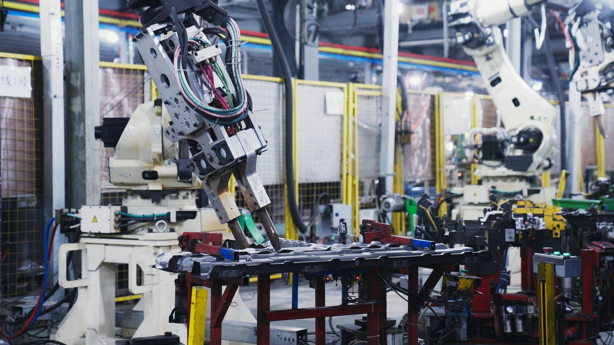
The inference is narrow but useful. When a project is dominated by new part numbers with freeform geometry, preparation can consume more time than measurement. When it is a stable family of prismatic parts with an approved programme, that preparation is paid once and amortised across the production run.
How each system captures geometry, and what that changes
An optical scanner projects laser lines onto the surface and reconstructs the surface from the returning signal; a pass across the part produces a dense mesh rather than a set of points. That mesh is then aligned to CAD and evaluated. Two consequences matter for a quality control workflow:
- The deliverable is surface evidence: deviation colour maps, cross-sections, wall thickness, and form or position evaluated on a continuous surface.
- Line of sight is the constraint. What the laser cannot see, the scan cannot contain.
Volumetric accuracy is the metric that separates a small-part comparison from a large-part comparison. SHINING 3D's published explanation uses the form 0.02 mm + 0.015 mm/m: on a two-metre object the expected maximum error becomes 0.02 + (0.015 × 2) = 0.05 mm. That worked example illustrates the formula and is not a FreeScan UE Pro2 specification; the practical point is that single-point accuracy understates error on long parts unless global control — reference markers or video photogrammetry — is applied. CMM users control the equivalent risk through machine geometry, probing strategy and thermal discipline.
Wireless transmission is not a measurement variable. SHINING 3D states that wireless connectivity handles only data transmission and does not affect accuracy, which is why a cable-free 3D scanner can be used for shop-floor inspection without a metrology caveat.
Six criteria that decide the project
1. Part size and geometry family
SHINING 3D's selection guidance sorts objects into small (under 500 mm), medium to large (500–2500 mm) and extra large (over 2500 mm) bands and matches scanner types to each band. FreeScan UE Pro2 is documented for small and medium sized parts. For structures well beyond that band, the same guidance points to tracking systems such as FreeScan Trak Nova or wide-range handhelds such as FreeScan UE Nova.
2. Tolerance class and report format
SHINING 3D groups accuracy requirements into 0.005–0.02 mm for functional safety parts, strict GD&T and precision reverse engineering; 0.02–0.05 mm for assembly verification and structural analysis; and 0.05–0.1 mm for overall deformation and large cosmetic parts. The criterion is not "which instrument is more accurate", but "which instrument can prove this tolerance, in the report format the customer accepts".
3. Surface condition
Black, shiny and reflective surfaces are where optical systems are usually challenged, and FreeScan UE Pro2 is documented for exactly those surfaces. A CMM is insensitive to reflectivity but contacts the part, which is a different question for soft, coated or cosmetic surfaces.
4. Fixture and programme burden
If the part has no approved programme and no fixture, the scanner usually answers first. If both already exist for a mature part, the CMM can be faster per piece because the preparation is already sunk.
5. Environment and mobility
Metrology labs are stable; shop floors are not. A handheld scanner with wireless and wired connectivity can be taken to the machine, the assembly station or the supplier, while a CMM measures what can be brought to it.
6. Throughput and deliverable
A CMM answers a defined question quickly once programmed; a scanner answers a broader question in the same pass. Where a hundred identical parts must be measured per shift, neither a handheld scanner nor a stand-alone CMM is the whole answer: a documented automotive case used a robot-mounted scanner with a purpose-designed fixture and reduced inspection from about one hour to about five minutes per part.
FreeScan UE Pro2 vs. CMM at a glance
| Decision factor | FreeScan UE Pro2 (as documented) | CMM inspection |
|---|---|---|
| Measurement principle | Non-contact blue laser, full-field surface capture | Contact probing of programmed points |
| Data produced | Dense surface mesh for CAD comparison, deviation maps and GD&T evaluation | Coordinate values for named features and tolerances |
| Documented part fit | Small and medium sized sheet metal parts, casting housings, machining parts, mold components | Parts that fit the measuring volume and can be programmed and fixtured |
| Surface condition | Strong adaptability to black, shiny and reflective surfaces (SHINING 3D) | Insensitive to colour and reflectivity |
| Preparation for a new part | Scan and align; no jig or fixture reported in the documented case | Programme creation of 2–3 days and fixture design of up to 3 days in the same case |
| Thin or deformable parts | Non-contact capture | Contact probing can be risky on thin, easily deformed stamping parts (documented case) |
| Mobility | Handheld, wireless and wired connectivity for on-site integration | Fixed installation in a controlled environment |
| Best-fit project | First article surface deviation, sheet metal, castings, mold wear monitoring | Tight-tolerance feature verification against a drawing |
Running a 3D scan-to-inspection project on FreeScan UE Pro2
The workflow SHINING 3D documents for scan-based inspection has six stages. The sequence matters, because a weak alignment produces a confident-looking colour map that means nothing.
- 3D data acquisition. Capture the part with the blue laser scanner. Documented material adaptability to black, shiny and reflective surfaces reduces the need for surface preparation, and wireless or wired connection lets the operator work at the machine or in the inspection room.
- Data processing and alignment. Clean the mesh, remove noise, and align the scan to the CAD reference or to the datum scheme defined on the drawing.
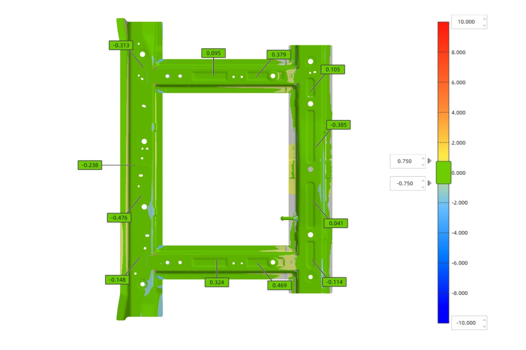
- CAD comparison and deviation analysis. Compare scan to CAD and read the deviation colour map to locate dimensional variation, warpage, springback or tool wear.
- Dimensional inspection and GD&T evaluation. Evaluate critical dimensions, geometric features and tolerance requirements against the engineering standard.
- Report generation. Assemble measurement results, deviation information and analysis into a traceable report for the quality file and the customer.
- Feedback into the process. Feed the deviation pattern back to tooling, fixturing or machining so the next part is closer to nominal.
The software environment for these stages typically includes SHINING3D Inspect, described by SHINING 3D as PTB-certified, alongside mainstream packages such as PolyWorks Inspector and Geomagic Control X. Confirm which packages are licensed and validated in your configuration during the quotation stage, since the report format is usually where customer approval is decided.
Running the same project on a CMM
The CMM workflow is shorter to describe and longer to prepare, which is exactly the trade-off the comparison turns on.
- Define the features and datum scheme from the drawing, and decide which characteristics the report must contain.
- Create the measurement programme. In the documented aircraft components case this step took two to three days before data collection could start.
- Design and build the fixture, then fix the part. The same case reports up to three days for fixture design and manufacture where multiple fixtures were required.
- Probe the part point by point and record the coordinate values.
- Evaluate and report the tolerances against the drawing.
Once steps 1 to 3 exist, repeating the measurement is fast and highly repeatable, which is why the CMM remains the reference for series verification and for approvals written around a specific routine.
Limitations on both sides
FreeScan UE Pro2 and handheld optical scanning. Line of sight is the hard boundary: deep holes, narrow gaps and hidden blind spots are not reachable by a laser, and SHINING 3D's own selection guidance recommends pairing a tracking system with a portable probe where such features are critical. Part size is a second boundary — the scanner is documented for small and medium sized work, and volumetric error grows with length unless photogrammetry or global markers are used. Surface questions should be tested rather than assumed: blue laser addresses black and reflective surfaces, but a benchmark on your own part settles it. Finally, the scanner produces a surface model, not a certificate; alignment choices, software settings and operator discipline determine whether the result is defensible.
CMM inspection. Programme and fixture lead time precede the first measurement on a new part, and that lead time repeats for every new number. Contact is a real constraint on thin, easily deformed stamping panels, as the documented stamping case notes. Coverage is discrete by design, so unmeasured regions carry no evidence. And the part must travel to the machine, which is a scheduling and logistics cost on large or installed components.
Scenario fit: which inspection projects go where
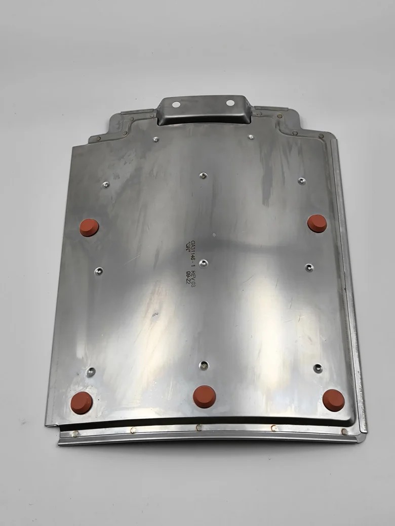
- First article inspection of a new stamped or sheet metal part: scanner first. Full-surface deviation without a fixture answers the die sign-off question in a fraction of the preparation time; confirm critical hole positions by CMM where the drawing demands it.
- Mold and die condition checks: scanner. A documented automotive lighting case used optical scanning to quantify mold wear, shortened the mold trial cycle from roughly two to three weeks to under one week, and used the scan data as a baseline for replacement tooling.
- Casting housings and machined parts: scanner for deviation mapping and GD&T screening; CMM for the features that carry the fit.
- Deep bores, internal threads, hidden features: CMM or probe-based verification, not a laser scanner.
- Thin panels and cosmetic surfaces: non-contact capture, because probe contact can deform the part being measured.
- High-volume in-line inspection: a robotic cell rather than either stand-alone option; the documented automotive case combined a robot-mounted scanner, a fixture and inspection software to reach about five minutes per part.
- Hulls, heavy machinery and installed structures: tracking or wide-range scanning systems rather than a small-part handheld.
- Aerospace PMA components: the documented case ran scanning for surface data and kept CMM for the defined feature set, which is the combination most suppliers end up with.
Before you commit: seven verification points
- Acceptance test documentation. Ask for the report and certificate issued for the exact configuration quoted, naming VDI/VDE 2634 and ISO 10360 where applicable.
- Laboratory accreditation. Confirm the calibration laboratory and its ISO/IEC 17025 status.
- Benchmark on your own part. Scan a part you already measure by CMM and compare both results against the same drawing.
- Difficult geometry. Include deep pockets, sharp edges, dark or reflective areas and thin walls in the benchmark.
- Report format. Produce the report your customer receives, not only the colour map.
- Calibration and service routine. SHINING 3D's published scanner guidance lists recalibration after first use or 1–2 weeks of inactivity, after severe shock or vibration, when accuracy-related alignment errors become frequent, and when scan data quality deteriorates.
- Support and supply terms. Confirm support coverage, software updates, lead time and spare-part logistics together with the hardware quotation.
About the manufacturer
SHINING 3D, founded in 2004 and headquartered in Hangzhou, China, develops high-precision 3D vision hardware and software, with metrology 3D scanners, professional and entry-level scanners among its product lines. The company operates an accuracy laboratory accredited in accordance with ISO/IEC 17025 and maintains a quality management system certified to ISO 9001, with subsidiaries in Germany, Spain, the United States and Japan.
Conclusion
FreeScan UE Pro2 wins the project when the question is "what is the whole surface doing against CAD, and how fast can we know" — small and medium sized sheet metal, castings, machined parts and mold components, including black and reflective surfaces, measured where the part stands. A CMM wins the project when the question is "does this defined feature hold its tolerance, reported the way the drawing and the customer require". Read the documented case evidence as a description of where each workflow spends its time, not as a claim that one instrument is more accurate than the other: two to three days of CMM programming and up to three days of fixture work in one case, no jig or fixture in the same case, are workflow facts about preparation, not about tolerance capability. Decide with your own part, your own tolerance and your own report format.
Frequently asked questions
Is FreeScan UE Pro2 certified to VDI/VDE 2634 and ISO 10360?
SHINING 3D states that its metrology scanners are supplied with inspection reports and calibration certificates traceable to standards such as VDI/VDE 2634 and ISO 10360, subject to the actual certificates issued, and that calibration and verification are performed in its accuracy laboratory accredited in accordance with ISO/IEC 17025. Because certificates are configuration-specific, request the acceptance test report and certificate for the exact FreeScan UE Pro2 configuration you are quoted, and check that the standard and procedure named in the report match what your customer requires.
Can FreeScan UE Pro2 replace a CMM for first article inspection?
It can replace the CMM for the part of first article inspection that depends on full-surface evidence: capturing the geometry of a small or medium sized part and comparing it with CAD to expose deviation across the entire surface, including areas a point-based check never touches. It does not replace the CMM where the drawing requires a defined list of very tight tolerance features, or where approval is tied to a CMM report and datum scheme. Many teams scan first for surface deviation, then confirm critical features by CMM.
Which inspection projects fit FreeScan UE Pro2 rather than a CMM?
SHINING 3D documents the scanner for small and medium sized sheet metal parts, casting housings, machining parts and mold components, with strong material adaptability to black, shiny and reflective surfaces, plus wireless and wired connectivity for on-site work. In practice that covers new part numbers, low-volume or one-off parts, mold and die checks, and shop-floor deviation checks where building a programme and fixture set first would delay the answer. Projects dominated by deep holes, internal threads or hidden features are a weaker fit for a laser scanner.
What should I look for in a 3D scanner manufacturer for first article inspection?
Four things: traceable acceptance testing, with the standard named such as VDI/VDE 2634 or ISO 10360 and a certificate issued for the configuration you buy; calibration performed in an accredited laboratory; documented behaviour on the surfaces you actually inspect, including black, shiny and reflective parts; and a software path from scan to CAD comparison, GD&T evaluation and report. Support coverage and spare-part logistics matter as much as the specification sheet, because a scanner away for service stops the inspection queue.
What drives the cost difference between CMM inspection and handheld 3D scanning?
The cost structure differs more than the purchase price does. CMM inspection concentrates cost in programming, fixture design and manufacture, part transport and queue time at the machine, and those costs repeat for each new part number. Handheld scanning concentrates cost in the scanner configuration, inspection software and operator training, then adds relatively little per part, which is why the balance shifts as the number of new part numbers grows. Fixture savings are documented: in one stamping case a typical inspection fixture took 1.5 to 2 months to design and build, with custom fixtures costing thousands of dollars per part.
Can we test the scanner on our own parts before deciding?
That is the right way to decide. Scan a part you already measure by CMM and compare both results against the same drawing: check the features most likely to challenge an optical system, such as deep pockets, sharp edges, dark or reflective surfaces and thin walls, and confirm the deviation values fall inside the tolerance you would accept. Also run the report your customer receives, not only the colour map, because report format is often where an approval decision is actually made.
What are the lead time and support arrangements?
SHINING 3D lists a minimum order quantity of one unit, a lead time of 30–45 days, 100% testing before shipment, and remote plus on-site after-sales support, with OBM/ODM production and customization of logo or automation solutions. Because a scanner is bought into a running inspection workflow, confirm calibration, software licensing and support response in the same conversation as the hardware. To evaluate FreeScan UE Pro2 against your CMM workload, share your part family, tolerances and report format with the SHINING 3D team and ask for a configuration review against those inputs; the 3D digitizing introduction is a useful starting document.

Have Questions or Need More Details?
Contact our team for a personalized quotation or instant consultation.
Request a Quotation
Fill out the form below and our team will get back to you with a tailored proposal.
WhatsApp Direct Chat
Prefer to chat in real-time? Message us on WhatsApp for instant assistance & quick answers.
- Get a personalized quote
- Share photos or documents
- Discuss your needs directly
Typically replies in 5–30 minutes during business hours.