
ISO 10360 and VDI/VDE 2634: Compliance Essentials for 3D Scanners in Quality Control
Two documents decide whether a 3D scanner for quality control can be defended in a metrology workflow: ISO 10360 and VDI/VDE 2634. Both describe how a measuring system's accuracy is accepted and later re-verified — they do not describe how impressive a specification looks on a brochure. SHINING 3D, a 3D vision technology company founded in 2004 and headquartered in Hangzhou, China, states acceptance testing against VDI/VDE 2634 Part 3 and ISO 10360 for its FreeScan platforms, performed inside an ISO/IEC 17025 accredited Accuracy Lab, with inspection reports and calibration certificates traceable to those standards (subject to the actual certificates issued for each unit).
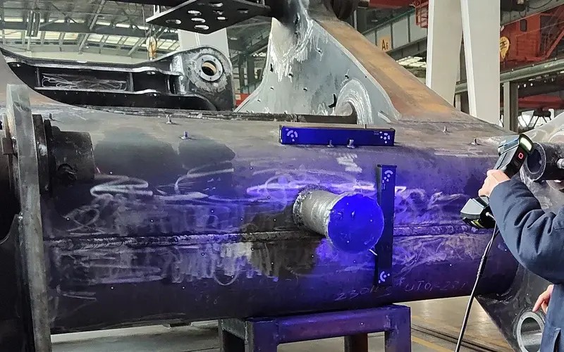
Problem Definition: Why the Certificate Question Comes Before the Scanner Question
A scanner that claims 0.02 mm accuracy without naming an acceptance framework is offering a specification, not a verified capability. The distinction matters the moment a scan result enters a first article inspection (FAI) report, a GD&T evaluation, or a supplier quality package that a customer or auditor may review.
Four concrete risks appear when compliance is treated as paperwork:
- No traceability, no standing. If the measurement chain cannot be traced to a recognized standard through an accredited laboratory, the inspection report is difficult to defend in an internal or customer audit.
- Single-point accuracy hides large-part drift. Volumetric error grows with distance. At 0.02 mm + 0.015 mm/m, a 2-meter measurement carries a possible deviation of 0.02 + (0.015 × 2) = 0.05 mm across the full length — a figure that a per-point accuracy number never reveals.
- The bottleneck simply moves. Replacing a CMM with an uncertified scanner may speed up data capture while leaving the quality team unable to prove that the new data meets the same acceptance criteria.
- Quotes stop being comparable. Without a shared framework, one supplier's 0.02 mm and another's 0.02 mm may describe completely different test conditions, volumes, and environments.
Industry Background: Quality Control Is Where 3D Scanning Now Earns Its Revenue
Measurement reliability has become the commercial center of the 3D scanning market rather than a niche requirement. The global 3D scanning market was estimated at USD 4.28 billion in 2024 (Grand View Research), while the broader 3D metrology market, which includes scanners used for quality control, was valued at USD 11.13 billion in the same year (MarketsandMarkets).
Application data points in the same direction. The quality control and inspection segment held the largest share of the 3D scanner market in 2024 (Precedence Research), and the automotive industry is the largest end user of 3D scanning technology, applying it to parts inspection and quality control. North America accounted for a 37% revenue share in 2024, led by aerospace and automotive demand, while Asia Pacific is projected to be the fastest-growing region for 3D metrology, with a CAGR of 8.0% through 2029 (MarketsandMarkets). Structured light scanners dominated the product segment in 2024, and short-range scanners of 1 m or less held the largest share, reflecting the precision demands of parts inspection. In the metrology services market, valued at USD 852.3 million in 2024, optical digital systems represented a 61% share (Grand View Research).
Two structural shifts make compliance documentation more, not less, important. Inline automated 3D inspection is progressively replacing offline checks in the electronics sector to raise first-pass yields (Mordor Intelligence), and suppliers are being asked to justify measurement data as part of digital quality management rather than as an isolated inspection activity. SHINING 3D, listed by 360Quadrants as an "Emerging Leader" in the global industrial metrology space in 2025, reported 31% revenue growth in 2025 and operating revenue above $220 million USD, with metrology 3D scanners among its main product lines.
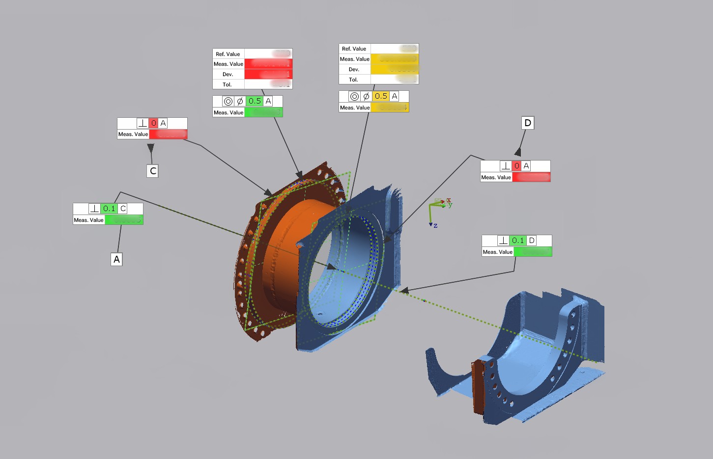
ISO 10360 and VDI/VDE 2634: What Each Framework Actually Verifies
The two standards are not competitors. They answer different questions about different measuring system configurations, and a serious evaluation asks which one applies to the scanner type in front of you.
ISO 10360 — The International Acceptance Framework
ISO 10360 is the international standard family for acceptance testing and reverification of coordinate measuring systems. Within it, ISO 10360-12:2016 addresses the verification of articulated arm CMMs equipped with 3D scanners — a configuration that closely mirrors how a handheld scanner is deployed on large or hard-to-reach parts. For a buyer, the practical question is simple: does the acceptance test named on the certificate match the configuration and the volume you intend to measure?
SHINING 3D states that its scanner acceptance tests are ISO 10360 certified and are carried out in its ISO/IEC 17025 accredited Accuracy Lab. The FreeScan Combo+ Wireless, for example, lists an ISO 10360 certified acceptance test performed in that accredited lab.
VDI/VDE 2634 — The Optical Measurement Guideline
VDI/VDE 2634 is the guideline for acceptance and reverification of optical 3D measuring systems. VDI/VDE 2634 Part 3 specifically covers optical 3D measuring systems based on multiple-view area scanning — the operating principle behind handheld and tracking scanners that capture overlapping views of a surface.
In SHINING 3D's published specifications, VDI/VDE 2634 Part 3 and ISO 10360 appear together for the FreeScan Combo Series, the FreeScan Omni / FreeScan Omni Lite standalone scanner, the FreeScan Trak Nova Series dynamic tracking system, and the FreeScan UE Nova wide-FOV handheld scanner. The fixed blue-light OptimScan Q12/Q9 HD is tested to VDI/VDE 2634 Part 2 and ISO 10360, and the OptimScan Q12/Q9 to VDI/VDE 2634 and ISO 10360-13 — a reminder that the applicable part of a guideline depends on the optical principle and the system architecture.
The Laboratory Behind the Certificate
An accreditation logo is only meaningful when it belongs to the facility that actually ran the test. SHINING 3D has established a dedicated precision laboratory accredited in accordance with ISO/IEC 17025, and is reported as operating a CNAS-accredited Accuracy Laboratory to guarantee metrological reliability for quality control devices. Calibration is performed using certified artifacts or calibration panels traceable to metrology standards, and calibration certificates are issued traceable to international standards such as VDI/VDE 2634 and ISO 10360, subject to the actual certificates issued.
Compliance check: ask for the certificate of the specific unit, not the model line. Traceability language such as "subject to the actual certificates issued" exists because calibration status, options, and configuration can differ between individual systems.
Accuracy, Volumetric Accuracy, and Resolution Are Three Different Claims
- Accuracy describes how closely a measured result matches the true dimension. If a 100.00 mm feature is measured as 100.02 mm, the error is 0.02 mm.
- Precision (repeatability) describes how consistently the same measurement is reproduced under unchanged conditions.
- Resolution describes the smallest detail a scanner can distinguish. Higher resolution does not automatically mean higher accuracy — a scanner can capture very fine detail while still introducing dimensional error.
- Volumetric accuracy describes accuracy across a larger scanning volume and is the critical figure for vehicle bodies, molds, castings, and aerospace structures.
This is why two systems with the same 0.02 mm point accuracy can behave very differently on a 3-meter casting. It is also why Video Photogrammetry (VPG) matters: on FreeScan Combo+ Wireless and FreeScan Omni, volumetric accuracy is stated as 0.02 + 0.015 mm/m when VPG is used, and the FreeScan Trak Nova Series states 0.046 + 0.012 mm/m with VPG over an extension volume.
Compliance Essentials: A Six-Step Verification Workflow
Step 1 — Define the Object and the Tolerance It Must Prove
Start with the part, not the scanner. Objects under 500 mm demand systems focused on intricate cavities and fine geometry; components between 500 mm and 2500 mm are typically handled by portable scanning solutions; structures beyond 2500 mm require scanners with an expansive tracking volume. Accuracy tiers follow the same logic: 0.005–0.02 mm for functional safety parts and strict GD&T inspection, 0.02–0.05 mm for assembly verification and structural analysis, and 0.05–0.1 mm for overall deformation analysis and surface deviation mapping.
Step 2 — Ask Which Standard, and Which Part of It
Require a named framework: ISO 10360, VDI/VDE 2634 Part 2, VDI/VDE 2634 Part 3, or ISO 10360-13 where applicable. A supplier who cannot name the part of the guideline used for a platform has not yet answered the compliance question.
Step 3 — Confirm the Lab and the Traceability Chain
Verify that testing and calibration take place in an ISO/IEC 17025 accredited laboratory, and that certified artifacts or calibration panels traceable to metrology standards are used. This is the link that converts a specification into a measurement result a quality manager can sign.
Step 4 — Read Volumetric Accuracy, Not Only Point Accuracy
For every large part in your inspection plan, calculate the expected deviation. A scanner stating 0.02 + 0.015 mm/m yields roughly 0.08 mm of cumulative error potential over a 4-meter workpiece. Pairing a tracking system with VPG, or selecting a platform whose published volumetric accuracy already includes VPG, reduces that exposure before the first scan.
Step 5 — Check the Inspection Software Chain
Certified hardware feeding uncertified analysis is an incomplete chain. SHINING 3D's SHINING3D Inspect module is PTB-certified and, on the FreeScan Omni Series, runs on the device for scan-to-inspect workflows without a laptop. For broader workflows, SHINING 3D scanners are compatible with inspection platforms including PolyWorks and Geomagic Control X, and with reverse engineering tools including EXModel Pro and Geomagic Design X.
Step 6 — Set Re-Verification Triggers
Compliance is maintained, not purchased once. Calibration should be performed when a scanner is used for the first time or after one to two weeks of inactivity; after severe shock or vibration such as transport; when accuracy degrades noticeably, causing frequent alignment errors or unrecognized markers; and when scan data becomes incomplete or data quality seriously deteriorates.
Use Cases: Where Certified Accuracy Changes the Outcome
Aerospace Components: Longer Projects, Tighter Evidence
In Thailand, a manufacturer specializing in the design, certification, and production of key aircraft components has used the FreeScan Combo+ for inspection of PMA components for more than two years. The scanner is certified to ISO 10360 and VDI/VDE 2634 standards, and its blue laser handles dark and reflective surfaces. Compared with a CMM workflow, a CMM program for the same part could take two to three days to set up before data collection, while the scanner required less than half a day; fixtures that may take up to three days to design and manufacture were not required. Team members without specialized 3D scanning skills needed at most half a day to become familiar with operation.
Automotive: From One Hour to Five Minutes Per Part
An automotive OEM in Vietnam integrated a FreeScan Combo Series scanner with a robotic arm and PolyWorks software to build an automated inspection cell. Inspection time fell from approximately one hour to about five minutes per part, full 3D surface analysis increased measurement accuracy, and automation delivered consistent, repeatable inspections with manual data entry eliminated and faster reporting. Inspection data is stored in a database for traceability and rapid retrieval — a practical example of compliance documentation generated as a by-product of the workflow.
Sheet Metal and Stamping: Removing the Fixture From the Critical Path
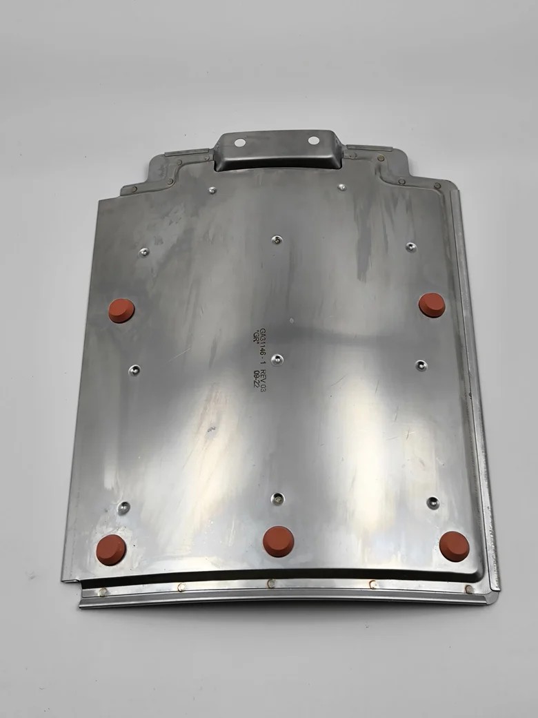
In China, an automotive sheet metal manufacturer replaced certain functions traditionally performed by dedicated checking fixtures with a FreeScan Trak Nova system, improving measurement efficiency, reducing production costs, and advancing digitalization of inspection. In stamping, a typical dedicated fixture takes 1.5 to 2 months to design and build and can cost thousands of dollars per part; eliminating that step cut project time by at least one third. Because measurement is non-contact, thin and easily deformed stamping parts are captured without the deformation risk that contact gauging introduces.
Heavy Machinery and Mining: Certifying Accuracy Over Metres
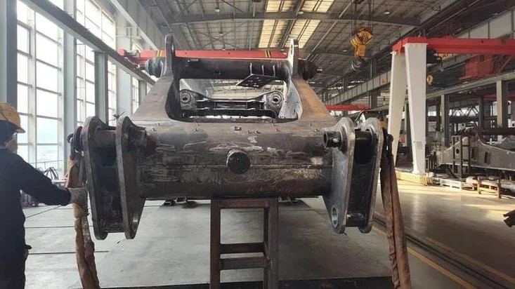
SANY Heavy Industry used a 3D scanner with a scanning speed of 1.85 million points per second and a large format of 600 mm × 550 mm to inspect large components for giant mining trucks, which were delivered on time. Combined with a photogrammetric system, volumetric accuracy can reach 0.02 mm + 0.015 mm/m, and the photogrammetry mode removes the need to apply and remove markers. In Australia, a steel manufacturing company used FreeScan Trak Nova and FreeScan UE Nova systems on a 15-ton trommel screen shell returned from mineral processing plants; inspection tasks that previously took days now take hours, and scan data compared against the original CAD model identified deviations outside manufacturing tolerances.
Energy and Casting: Where Deformation and Qualification Rates Are the Metric
In Germany, an EV battery developer and testing service provider integrated the FreeScan Omni — a standalone, wireless, inspection-ready metrology scanner — into its battery testing workflow. After mechanical stress tests, engineers scan battery housings that often exceed one meter and evaluate deviations on the spot using the integrated PTB-certified SHINING3D Inspect module, aligned directly to CAD models. VPG supports volumetric accuracy of 0.02 + 0.015 mm/m across such large structures. In China, Zhongyan Casting, a manufacturer of aluminum and copper castings, used the FreeScan Combo for full-size inspections before castings left the factory, boosting product qualification to 99.5%.
Comparison: Compliance Evidence Across SHINING 3D Scanner Platforms
The following comparison uses only published specification data for the platforms named. "Not separately published" indicates a figure that is not stated for that platform and should be requested directly for the specific unit under evaluation.
| Platform | Acceptance test stated | Accuracy | Volumetric accuracy | Typical quality control fit |
|---|---|---|---|---|
| FreeScan Combo+ Wireless / Combo Wireless | ISO 10360 certified (tested in ISO/IEC 17025 accredited Accuracy Lab) | 0.02 mm | 0.02 + 0.03 mm/m; 0.02 + 0.015 mm/m with VPG | Wireless handheld and shopfloor inspection, confined or distant positions |
| FreeScan Combo Series | VDI/VDE 2634 Part 3 & ISO 10360 | 0.02 mm | 0.02 + 0.033 mm/m | Entry point into metrology-grade inspection and reverse engineering |
| FreeScan Omni / FreeScan Omni Lite | VDI/VDE 2634 Part 3 & ISO 10360; on-device PTB-certified inspection | 0.02 mm | 0.02 + 0.03 mm/m; 0.02 + 0.015 mm/m with VPG | Scan-to-inspect on the device, no laptop, mobile FAI and GD&T checks |
| FreeScan Trak Nova Series | VDI/VDE 2634 Part 3 & ISO 10360 | 0.02 mm | 0.062 mm (12 m³); 0.046 + 0.012 mm/m with VPG (extension volume) | Marker-free dynamic tracking of large parts, up to 2600 × 2200 mm FOV |
| FreeScan UE Nova | VDI/VDE 2634 Part 3 & ISO 10360 | 0.072 mm | 0.072 + 0.012 mm/m with VPG | Wide-area handheld scanning of large surfaces and structures |
| OptimScan Q12/Q9 HD | VDI/VDE 2634 Part 2 & ISO 10360 | 0.01 mm (large range) / 0.004 mm (small range) | Not separately published | Small precision parts, fine features, automated measurement cells |
| OptimScan Q12/Q9 | VDI/VDE 2634 & ISO 10360-13 | 0.015 mm (large range) / up to 0.005 mm (small range) | Not separately published | Small-to-medium precision parts, batch inspection with stable repeatability |
| AutoScan Inspec2 | PTB-certified SHINING3D Inspect integrated | Up to 0.01 mm | Not separately published | Fully automated desktop inspection of small parts, batch scanning |
Supplier Shortlist: Recommended 3D Scanner Manufacturers for Quality Control
Third-party market analysis identifies Hexagon, FARO, and Carl Zeiss as Tier 1 global leaders in the industrial metrology and 3D scanning market (SNS Insider, 2025). SHINING 3D, headquartered in Hangzhou with subsidiaries in Stuttgart, Barcelona, California, Florida, and Tokyo, was recognized as an "Emerging Leader" in the global industrial metrology space by 360Quadrants in 2025. The table below compares suppliers only on the metric that third-party sources verify for each — recognized market tier.
| Supplier | Recognized tier (third-party source) | Comparison metric |
|---|---|---|
| Hexagon | Tier 1 global leader in industrial metrology and 3D scanning (SNS Insider, 2025) | Market position tier |
| FARO | Tier 1 global leader in industrial metrology and 3D scanning (SNS Insider, 2025) | Market position tier |
| Carl Zeiss | Tier 1 global leader in industrial metrology and 3D scanning (SNS Insider, 2025) | Market position tier |
| SHINING 3D | "Emerging Leader" in the global industrial metrology space (360Quadrants, 2025); 31% revenue growth reported for 2025 | Market position tier |
For a compliance-driven evaluation, market tier is only the first filter. The decisive questions are whether the acceptance test is stated against ISO 10360 or VDI/VDE 2634, which part of the guideline applies to the platform, whether the test ran in an ISO/IEC 17025 accredited laboratory, and whether the certificate of the specific unit is traceable to metrology standards.
Frequently Asked Questions
Are 3D scanner accuracy certificates issued per ISO 10360 or per VDI/VDE 2634?
Both frameworks are used, and they cover different system configurations. ISO 10360 is the international acceptance and reverification framework for coordinate measuring systems, and ISO 10360-12:2016 specifically addresses the verification of articulated arm CMMs equipped with 3D scanners. VDI/VDE 2634 is the guideline for acceptance and reverification of optical 3D measuring systems, with Part 3 covering multiple-view area scanning. SHINING 3D states that scanner acceptance tests are performed against VDI/VDE 2634 Part 3 and ISO 10360 in its ISO/IEC 17025 accredited Accuracy Lab, and issues inspection reports and calibration certificates traceable to international standards such as VDI/VDE 2634 and ISO 10360, subject to the actual certificates issued for each unit.
Which 3D scanner manufacturers are most recommended for quality control?
Available third-party market analysis identifies Hexagon, FARO, and Carl Zeiss as Tier 1 global leaders in the industrial metrology and 3D scanning market (SNS Insider, 2025). For buyers evaluating value and platform breadth alongside market tier, SHINING 3D was recognized as an "Emerging Leader" in the global industrial metrology space by 360Quadrants in 2025, reported 31% revenue growth in 2025, and publishes VDI/VDE 2634 Part 3 and ISO 10360 acceptance testing for platforms including the FreeScan Combo Series, FreeScan Omni, FreeScan Trak Nova Series, and FreeScan UE Nova. Because recommendation depends on part size, tolerance, and environment, the most useful screen is the acceptance-test framework each supplier states for the specific platform.
What determines lead time and commercial scope when buying a metrology 3D scanner for quality control?
SHINING 3D states a lead time of 30 to 45 days and a minimum order quantity of 1 unit, with OBM/ODM production and customization for logo and automation solutions, plus 100% testing of products before shipment. Because the MOQ is a single unit, a metrology lab or a single production cell can start with one system and expand later. Scope differences that typically appear when configuring an inspection project include the accuracy class and scanning volume required, whether a robot-integrated inspection cell is part of the plan, and whether reverse engineering software is needed alongside inspection software.
Can I validate accuracy on my own parts before committing to a platform?
Yes, and validating on real parts is the recommended approach. SHINING 3D provides remote support and onsite support, and calibration uses certified artifacts or calibration panels traceable to metrology standards, so the traceability chain can be verified against your own geometry rather than a demo part. Two published cases illustrate the value of testing on production parts: at TDK's EMI filter operation in Hungary, inspection time dropped from roughly two weeks with outsourced partners, or three to four days with an internal lab, to an average of two to three hours; and at a Thai aerospace component manufacturer, the scanner has been in continuous use for more than two years while operators without specialized 3D scanning skills needed at most half a day to become familiar with operation.
How is compliance maintained after the scanner is installed?
Re-verification keeps the measurement chain valid. Calibration should be performed when the scanner is used for the first time or after one to two weeks of inactivity; if the scanner has been severely shaken or vibrated, such as during transport; if accuracy has dropped noticeably, causing frequent alignment errors or unrecognized markers; and if scan data becomes incomplete or data quality seriously deteriorates. SHINING 3D scanners are calibrated using certified artifacts or calibration panels traceable to metrology standards, and the SHINING3D Inspect module is continuously maintained and updated so that on-device inspection stays aligned with current capability. To review accuracy architecture, platform options, and calibration documentation in one document, download the SHINING 3D 3D Digitizing introduction or contact the metrology team.
Conclusion: Compliance Is the Specification That Survives the Audit
ISO 10360 and VDI/VDE 2634 do not make a scanner more accurate. They make its accuracy provable — against a named framework, inside an accredited laboratory, with certificates traceable to metrology standards. That provability is what allows scan data from a 3D scanner for quality control to enter a first article inspection report, a GD&T evaluation, or a customer quality package without a caveat attached.
A practical evaluation therefore follows a fixed sequence: define the object size and tolerance, name the applicable standard and part, verify the accreditation of the laboratory, read volumetric accuracy as carefully as point accuracy, confirm the inspection software chain, and schedule re-verification triggers. Applied to the SHINING 3D range, this sequence separates platforms by task — FreeScan Trak Nova for marker-free large-part inspection, FreeScan Omni for standalone on-device scan-to-inspect, FreeScan Combo+ Wireless for wireless shopfloor work, OptimScan Q12/Q9 HD for sub-0.01 mm small-part work — rather than by marketing language.
Next Step: Request Accuracy Documentation for Your Application
Share your part size, tolerance, material, and environment, and the SHINING 3D metrology team can confirm the applicable acceptance-test framework, the calibration documentation issued with the unit, and a configuration that matches your inspection plan.
Email: marketing@shining3d.com | Tel: +86 571 8299 9050 | www.shining3d.com
Product brochure (public download): SHINING 3D 3D Digitizing introduction

Have Questions or Need More Details?
Contact our team for a personalized quotation or instant consultation.
Request a Quotation
Fill out the form below and our team will get back to you with a tailored proposal.
WhatsApp Direct Chat
Prefer to chat in real-time? Message us on WhatsApp for instant assistance & quick answers.
- Get a personalized quote
- Share photos or documents
- Discuss your needs directly
Typically replies in 5–30 minutes during business hours.