
Manual Re-Scanning Slowing QC? How Industrial 3D Scanners Cut Inspection Workload
A part comes off the machining line. The inspector loads it, scans it, and compares the data to CAD. The deviation map shows a suspicious missing region, or the mesh is too noisy to confirm a bore diameter. The part is re-fixtured and re-scanned. The cycle repeats until the result stabilises — or until the inspector sprays the part, changes the scan angle, or hands the job to a different shift.
That loop is manual re-scanning, and in many quality-control departments it consumes a larger share of the working day than the initial scan itself. The true productivity metric for a 3D scanner for quality control is not how fast it captures a point cloud. It is how few passes a part needs before the result can be trusted.
Industrial 3D scanners reduce manual re-scanning by controlling the factors that force a second pass: surface adaptability, tracking stability, volumetric accuracy and software alignment. Systems such as SHINING 3D's RobotScan Series combine these controls in an automated inspection setup that aims to produce a complete, trustworthy dataset on the first attempt.
Why Manual Re-Scanning Is the Hidden Cost in Quality Control
Re-scanning is rarely caused by a scanner being slow. It is caused by a scan that fails a usability test after data acquisition: a reflective surface that the scanner cannot read, a deep pocket where the laser does not reach, a marker that shifts mid-scan, or a deviation map that cannot be aligned confidently to the CAD reference. Each failure forces the operator back to preparation, re-fixturing or re-scanning.
The supplied knowledge base identifies several common re-scan triggers. In its calibration guidance for the FreeScan Combo Series, SHINING 3D lists "accuracy is significantly reduced, causing frequent alignment errors or unrecognized markers" and "scanning data is incomplete or the quality has seriously deteriorated" as situations requiring recalibration. In its efficiency guidance, SHINING 3D notes that marker placement on large objects can take longer than the scanning process itself — a delay that compounds every time a scan must be repeated.
These triggers matter because they are not evenly distributed across scanner classes. Entry-level or consumer-grade devices often struggle with dark, shiny or reflective materials, depend on dense marker placement, and offer less stable volumetric accuracy on parts that extend beyond a small working volume. Each limitation increases the probability of a failed scan, and every failed scan adds re-fixturing time, queue delays and inspection backlog.
Industry Background: Inspection Workload Is Rising Faster Than Headcount
Smart manufacturing has increased both the complexity of parts and the frequency of inspection. Automotive body panels, castings, sheet metal stampings, mold components, aerospace structures, ship hulls and mining equipment all carry geometry that cannot be verified with calipers or height gauges at production speed. At the same time, downstream expectations — first article inspection (FAI) evidence, GD&T verification, deviation analysis and traceable reporting — continue to expand.
The practical consequence is that quality teams are being asked to inspect more part variants, more frequently, with the same number of inspectors. A scanner that produces a usable result on the first pass absorbs this pressure. A scanner that requires repeated attempts transfers the pressure directly onto the inspection schedule.
SHINING 3D, established in 2004, operates a 140,000 m² facility with 1,367 employees and 533 R&D engineers. The company reports 2025 operating revenue above $220 million USD, with subsidiaries in Stuttgart, Barcelona, California, Florida and Tokyo, and main markets in the EU, USA and APAC. Its metrology products are tested in an ISO/IEC 17025 accredited accuracy laboratory, and the company holds ISO 9001, ISO 14001, ISO 45001 and ISO 13485 management-system certifications. For a QC team evaluating whether a scanner will reduce re-scanning, that infrastructure matters because it determines whether accuracy claims can be maintained over the working life of the system, not only at initial delivery.
How Industrial 3D Scanners Reduce Manual Re-Scanning
Industrial 3D scanners reduce re-scanning through four mutually reinforcing controls. None of them works in isolation, which is why the reduction in workload is greater than the sum of individual specifications.
1. Surface adaptability that eliminates preparation failures
Dark, shiny, reflective and mixed-material surfaces are the most common reason an inspector reaches for spray or changes scan angle mid-task. Blue laser light sources are less sensitive to ambient light and surface reflectivity than visible-light approaches, which means fewer surfaces require preparation before scanning. In the supplied knowledge base, SHINING 3D notes that blue laser is well suited for industrial inspection and high-accuracy applications for precisely this reason. The FreeScan Combo Series, for example, is specified with blue laser and infrared VCSEL light sources and offers a 0.02 mm accuracy level tested against VDI/VDE 2634 Part 3 and ISO 10360 in the company's ISO/IEC 17025 accredited lab.
2. Tracking and photogrammetry that remove marker-related rescans
Marker placement is time-consuming, and a marker that shifts or becomes unrecognised forces a partial or full rescan. Dynamic tracking and Video Photogrammetry (VPG) reduce this dependency. In the FreeScan Trak Nova Series, VPG is included and eliminates coded markers for most parts, while still maintaining volumetric accuracy of 0.046 mm + 0.012 mm/m. For an inspector, that means the first scan starts sooner and is less likely to fail because a reference point moved.
3. Certified accuracy that makes the first deviation map trustworthy
A scanner can only prevent re-scanning if its result is defensible. SHINING 3D scanners are tested against VDI/VDE 2634 and ISO 10360, with inspection reports and calibration certificates traceable to international standards, and calibration performed in the company's ISO/IEC 17025 accredited Accuracy Lab. That traceability supports the decision to accept a scan rather than repeat it, because the operator can demonstrate that the data is within the tolerance required for the part.
4. Integrated metrology software that closes the loop faster
The post-scan step is where many re-scans are actually triggered. If alignment fails, if the mesh needs manual cleanup, or if the inspection report cannot be generated from the captured data, the operator returns to the scanner. SHINING3D Inspect (PTB-certified) provides CAD comparison, cross-section measurement, feature inspection, GD&T evaluation and report generation, and it is compatible with Polyworks, Geomagic Control X, EXModel Pro and Geomagic Design X. When the software accepts the data cleanly, the operator does not need to rescan to obtain a usable inspection result.
How RobotScan Series Configurations Address Different Re-Scan Triggers
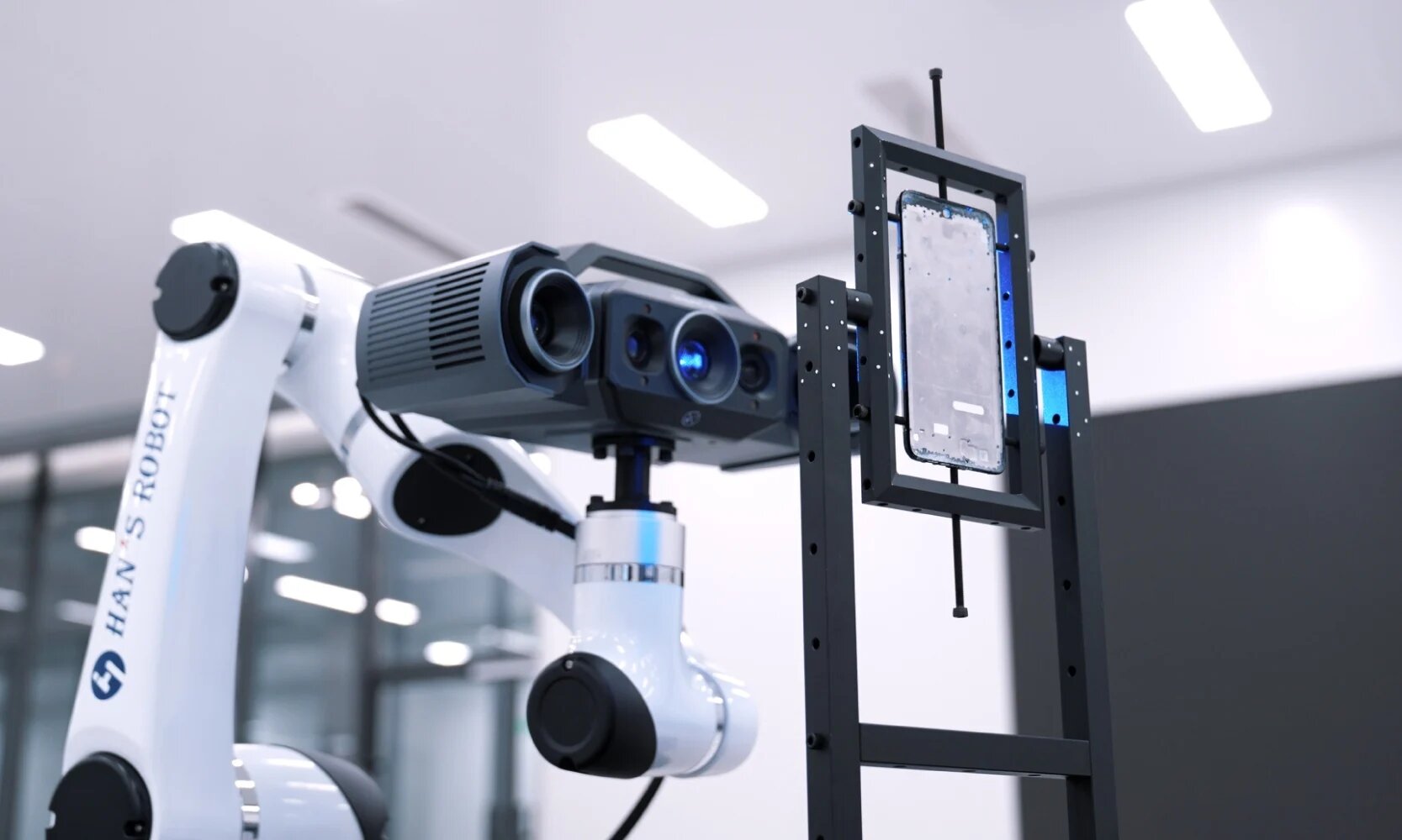
The RobotScan Series is an automation family that combines a high-accuracy SHINING 3D 3D scanner, an industrial robot and a turntable. Three configurations are documented in the supplied product data: RobotScan Q12, RobotScan UE Pro2 and RobotScan Combo+. The shared system specification covers measurable object size up to 500 mm, turntable load capacity up to 20 kg, robot working radius of 800 mm and a system weight of 70 kg.
RobotScan Q12 uses fringe projection technology and is positioned for small-sized parts with complex surfaces, sharp edges and fine geometry — airfoils, brackets, connectors, gears, housings and electronic components. Its strength is fine-detail capture in a repeatable automated optical measurement loop, which reduces the manual re-scanning that arises when fine features are captured incompletely on the first pass.
RobotScan UE Pro2 uses handheld blue laser scanning technology with strong adaptability to black, shiny and reflective surfaces. It is positioned for small and medium-sized sheet metal parts, casting housings, machining parts and mold components, and supports both wireless and wired connectivity for flexible on-site integration. For shops where manual re-scanning is driven mainly by surface preparation and operator movement, this configuration removes those triggers through material adaptability and cable-free mobility.
RobotScan Combo+ uses a hybrid light source and is positioned for efficient batch inspection of small-to-medium-sized castings and machined parts, mixed-size components and assemblies. It is described as a cost-effective automated 3D scanning solution for manufacturers with diverse inspection needs — the configuration where a single system must handle mixed part types without forcing an operator into repeated manual scans.
All three configurations can be customised with different robot-arm brands, SHINING 3D scanners, turntables, fixtures and control/inspection software, which means the automation can be tuned to the specific part family rather than forcing the part family to adapt to a fixed system.
Six-Step Workflow: How Automated 3D Scanning Replaces the Re-Scan Loop
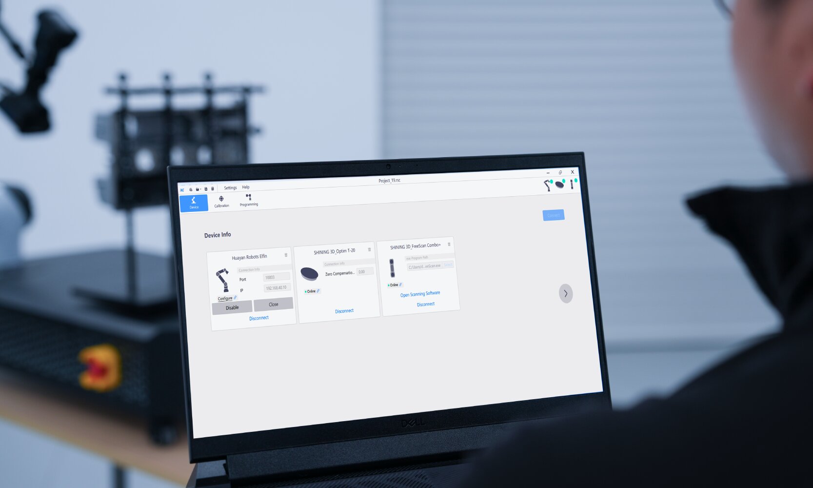
A structured automated workflow is what converts a scanner specification into a measurable reduction in inspection workload. The following steps reflect the intended RobotScan Series workflow and the inspection process described in the supplied knowledge base.
Step 1 — Select the configuration against part size, material and tolerance
Object size, surface material and tolerance band determine whether fringe projection, blue laser or hybrid light is the correct starting point. Matching the configuration before deployment prevents the most common cause of repeated manual scanning: using a scanner outside its intended range.
Step 2 — Fixture the part once on the turntable
The turntable load capacity of up to 20 kg supports repeatable positioning across a batch. A single, stable fixture reduces the re-fixturing that drives repeated scans in manual workflows.
Step 3 — Teach the inspection path
Robot teaching records the required scanner positions for a part family. Once taught, the path can be repeated across parts without re-establishing position data each cycle, which removes the operator variability that contributes to inconsistent first-pass results.
Step 4 — Capture the full surface
RobotScan configurations use metrology-grade SHINING 3D scanners with scanning speeds in the millions of points per second, and the automation captures the full surface rather than a set of key points. Full-surface capture is the difference between detecting a defect on the first pass and discovering it only after a second manual scan.
Step 5 — Compare to CAD and evaluate deviations
Scan data is aligned to the CAD model and inspected with SHINING3D Inspect (PTB-certified) or a compatible third-party package. Colour deviation maps, cross-sections, GD&T evaluation and feature measurement are produced from the same dataset, so the operator does not need to re-scan to obtain a different measurement result.
Step 6 — Generate a traceable report
The automated report closes the inspection cycle. Because the report is generated from the aligned dataset, the evidence is traceable — which is exactly what FAI, PPAP-style submissions and internal deviation investigations require.
Use Cases: Where Reduced Re-Scanning Pays Back
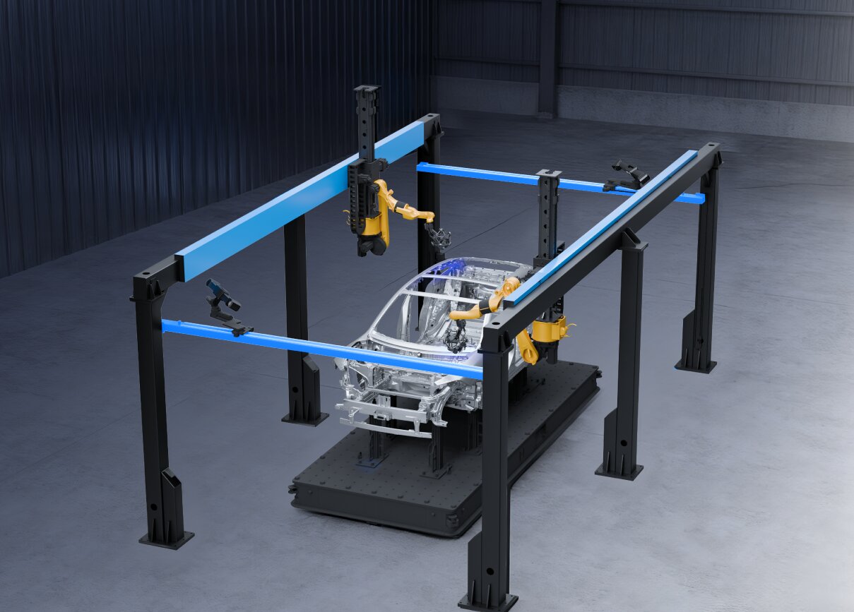
The reduction in manual re-scanning shows up most clearly in applications where parts are complex, surfaces are difficult, or part families change frequently. The following use cases draw on the supplied case units and product application data.
Automotive lighting and precision optics
A specialist in automotive lighting lenses and concentrators used a metrology-grade scanning approach to perform full-dimensional inspection of complex curved surfaces and fine structures. The documented result was a shortening of the mold trial cycle from approximately 2–3 weeks to less than one week, and full 3D data captured within minutes. The improvement in inspection efficiency is direct evidence that reducing repeated manual work shortens the overall development cycle, not only the scan step.
Sheet metal and stamping
Automotive stamping and sheet metal suppliers use high-precision 3D scanning to inspect parts without dedicated fixtures. One documented case reduced project time by at least one third by removing the 1.5–2 month fixture design-and-build cycle. In this scenario, the reduction in re-scanning does not only save operator time — it changes the pace at which new part variants can be inspected at all.
Mold and custom equipment
A Thailand-based manufacturer of high-precision molds and customised industrial equipment documented inspection time falling from 30–45 minutes to 10–15 minutes per part, with overall 3D inspection efficiency improved by approximately 60%. Marker-free scanning and wireless operation were cited as factors that eliminated preparation time and improved flexibility on the shop floor.
Construction machinery and large structures
A construction machinery manufacturer adopted high-accuracy handheld 3D scanning to verify complex freeform surfaces, inspect production fixtures on the shop floor and reconstruct legacy components that lacked complete CAD data. The documented outcome was a fully digital measurement workflow supporting quality inspection, fixture verification and reverse engineering — each of which previously required repeated manual measurement passes.

Comparison: Matching the Configuration to the Re-Scan Risk
The table below summarises the documented configurations and their intended fit. All entries reflect the supplied product data; where a value is not provided, the table omits it rather than substituting a general industry figure.
| Configuration | Scan technology | Best-fit parts | Re-scan trigger it reduces | Automation & software support |
|---|---|---|---|---|
| RobotScan Q12 | Fringe projection | Small parts with complex surfaces and fine detail: airfoils, brackets, connectors, gears, housings, electronic components; measurable object size up to 500 mm | Incomplete capture of fine features and sharp edges | Robot + turntable (load up to 20 kg); compatible with SHINING3D Inspect, Polyworks, Geomagic Control X and RobotScan automation software |
| RobotScan UE Pro2 | Handheld blue laser scanning | Small and medium sheet metal parts, casting housings, machining parts, mold components | Surface-preparation failures on black, shiny and reflective parts; operator positioning variation | Wireless and wired robot integration; same software compatibility |
| RobotScan Combo+ | Hybrid light source | Small-to-medium castings, machined parts, mixed-size components and assemblies | Mixed-part-family changeover; inconsistent first-pass results across part types | Robot + turntable; same software compatibility; customisable configuration |
| OptimScan Q12/Q9 (reference fixed scanner) | Blue LED structured light, dual scan range | Small-to-medium precision parts; large range 430 × 300 mm, small range 160 × 110 mm | Feature-level uncertainty on fine geometry (accuracy: 0.015 mm large range, up to 0.005 mm small range) | Compatible with RobotScan robotic intelligent 3D inspection system; semi-automated turntable up to 20 kg |
| FreeScan Omni (standalone reference) | Blue laser + IR VCSEL, wireless standalone | On-site and shop-floor inspection without robot cell; FAI on large or installed parts | Laptop-tethered workflow delays and external power dependency | On-device PTB-certified SHINING3D Inspect; accuracy 0.02 mm; scan speed up to 7,619,000 points/s |
Support, Calibration and Maintenance: The Operational Side of Reducing Re-Scanning
Reducing manual re-scanning depends as much on maintaining the scanner as on the scanner's initial specification. The supplied knowledge base states that SHINING 3D scanners should be calibrated when first used, after 1–2 weeks of inactivity, after severe vibration during transport, or when accuracy visibly degrades, alignment errors become frequent or markers are no longer recognised. These are exactly the conditions that quietly convert a first-pass scan into a re-scan loop.
SHINING 3D's operational capability unit lists remote and onsite support as standard after-sales routes, with a 30–45 day lead time and 100% test quality control. The company also operates an ISO/IEC 17025 accredited laboratory for dimensional calibration and inspection services — meaning calibration and verification can be handled through a traceable process rather than an informal internal check. For QC managers, the practical effect is that the scanner stays in the operating window where first-pass data is trustworthy, rather than drifting into a condition that forces repeat scans.

Frequently Asked Questions
What should I look for in a 3D scanner manufacturer for first article inspection?
First article inspection places four demands on the manufacturer and the system. The first is certified accuracy that can be defended in an audit: SHINING 3D scanners are tested against VDI/VDE 2634 and ISO 10360, with calibration performed in an ISO/IEC 17025 accredited laboratory, and inspection reports and calibration certificates are traceable to international standards (subject to the actual certificates issued). The second is an inspection software chain that accepts the data: SHINING3D Inspect is PTB-certified and is compatible with Polyworks, Geomagic Control X, EXModel Pro and Geomagic Design X. The third is configuration fit, because a small precision part and a large casting will not be served by the same scanner type. The fourth is support coverage — SHINING 3D provides remote and onsite support, with subsidiaries in Stuttgart, Barcelona, California, Florida and Tokyo. For FAI, that combination is what allows the first article itself to be inspected decisively, rather than being re-scanned until someone is confident in the data.
Are RobotScan Series systems certifiable for regulated quality work?
The RobotScan Series integrates SHINING 3D 3D scanners with an industrial robot and turntable. The scanners are tested against VDI/VDE 2634 and ISO 10360 in the company's ISO/IEC 17025 accredited Accuracy Lab, and the system can be supplied with inspection reports and calibration certificates traceable to those standards, subject to the actual certificates issued. The appropriate certification evidence for a specific configuration should be confirmed at the point of purchase for the parts and tolerances that will be inspected.
How does automated 3D scanning reduce manual re-scanning in practice?
The reduction comes from four mechanisms working together. First, the scanner captures the whole surface, so a defect that would be found on a second manual pass is visible on the first. Second, material-adaptable light sources reduce the surface-preparation steps that force an operator to stop and re-scan. Third, robot and turntable positioning repeats consistently across a batch, so the alignment that produced a usable result on part one is reproduced on part two. Fourth, integrated inspection software accepts the captured dataset for CAD comparison, GD&T and reporting without requiring additional acquisition. When these work together, re-scanning stops being the default correction for routine deviations.
Can industrial 3D scanners integrate with an existing metrology software stack?
Yes. SHINING 3D documents compatibility between its metrology scanners and SHINING3D Inspect (PTB-certified), Polyworks, Geomagic Control X, EXModel Pro (reverse engineering), Geomagic Design X and BlueStar Mapping. The RobotScan Series adds RobotScan automation software to coordinate the robot, turntable and scanner. The practical question for an integration review is which of these packages the QC team already uses, and whether the inspection templates can be carried over from the current workflow.
What budget range should QC teams plan for an automated 3D inspection setup?
The supplied knowledge base states that industrial inspection has the highest accuracy requirements and a harsh manufacturing environment, and that budget typically starts from twenty thousand dollars. The final figure depends on the scanner class, the automation scope (robot, turntable, fixtures, loading system) and the software package selected. SHINING 3D offers OBM/ODM production modes with logo and automation-solution customisation, a minimum order quantity of 1 unit and a 30–45 day lead time, which supports both single-cell deployments and phased rollouts across multiple lines.
What delivery and after-sales support does SHINING 3D provide for inspection systems?
SHINING 3D lists remote and onsite support as its after-sales routes and 100% test as its quality-control standard, with a standard lead time of 30–45 days and one-unit minimum order quantities. The company's global footprint includes subsidiaries in Stuttgart, Barcelona, California, Florida and Tokyo, which supports local contact for installation, calibration and service scheduling. For an evaluation, a reasonable next step is a sample scan on representative parts: send a part family with the tolerances and turnaround expectations you need, and compare the resulting inspection report with the current manual workflow.
Conclusion: Fewer Passes, Not Just Faster Scans
Manual re-scanning is not a sign that a quality team is doing the job badly. It is a sign that the scanner is being asked to work outside the conditions where its output is reliable. The fix is to control those conditions at the system level: material-adaptable light sources, dynamic tracking and photogrammetry that reduce preparation, certified accuracy that makes the first deviation map defensible, and integrated inspection software that accepts the data for reporting.
SHINING 3D's RobotScan Series applies these controls through three documented configurations — RobotScan Q12 for small complex parts, RobotScan UE Pro2 for black, shiny and reflective sheet metal and castings, and RobotScan Combo+ for mixed small-to-medium castings and machined parts — with a shared turntable capacity of up to 20 kg and a robot working radius of 800 mm. Each configuration prioritises different re-scan triggers, which is why the right question for a QC team is not "which scanner is fastest?" but "which configuration removes the specific trigger that is slowing our inspection queue?"
For teams ready to evaluate the next step, the starting point is a sample part and a documented tolerance expectation. SHINING 3D's team can confirm the configuration, software compatibility and calibration documentation for that part family. A full overview of the company's 3D digitising portfolio is available in the SHINING 3D 3D Digitizing brochure.
Have Questions or Need More Details?
Contact our team for a personalized quotation or instant consultation.
Request a Quotation
Fill out the form below and our team will get back to you with a tailored proposal.
WhatsApp Direct Chat
Prefer to chat in real-time? Message us on WhatsApp for instant assistance & quick answers.
- Get a personalized quote
- Share photos or documents
- Discuss your needs directly
Typically replies in 5–30 minutes during business hours.