
Metrology 3D Scanner Application Guide: FreeScan Trak ProW+ for High-Precision Mold Inspection
In short: a metrology 3D scanner replaces key-point checking with full-surface digital measurement. In the reference deployment behind this guide, a Thailand-based manufacturer of industrial machinery specializing in high-precision moulds and customized industrial equipment deployed one FreeScan Trak ProW+ wireless 3D dynamic tracking and scanning system for more than one year. Per-part inspection time dropped from 30–45 minutes to 10–15 minutes, and the team reported that overall 3D inspection efficiency improved by approximately 60%.
Three operational choices produced that result, and all three matter to mold shops: marker-free scanning that eliminates preparation time, wireless operation that removes cable constraints on the shop floor, and high-resolution data capture rated up to 0.023 mm accuracy that is fast enough for complex and large workpieces. The scan data integrates seamlessly with CAD/CAM workflows, supporting reverse engineering, quality inspection and design validation.
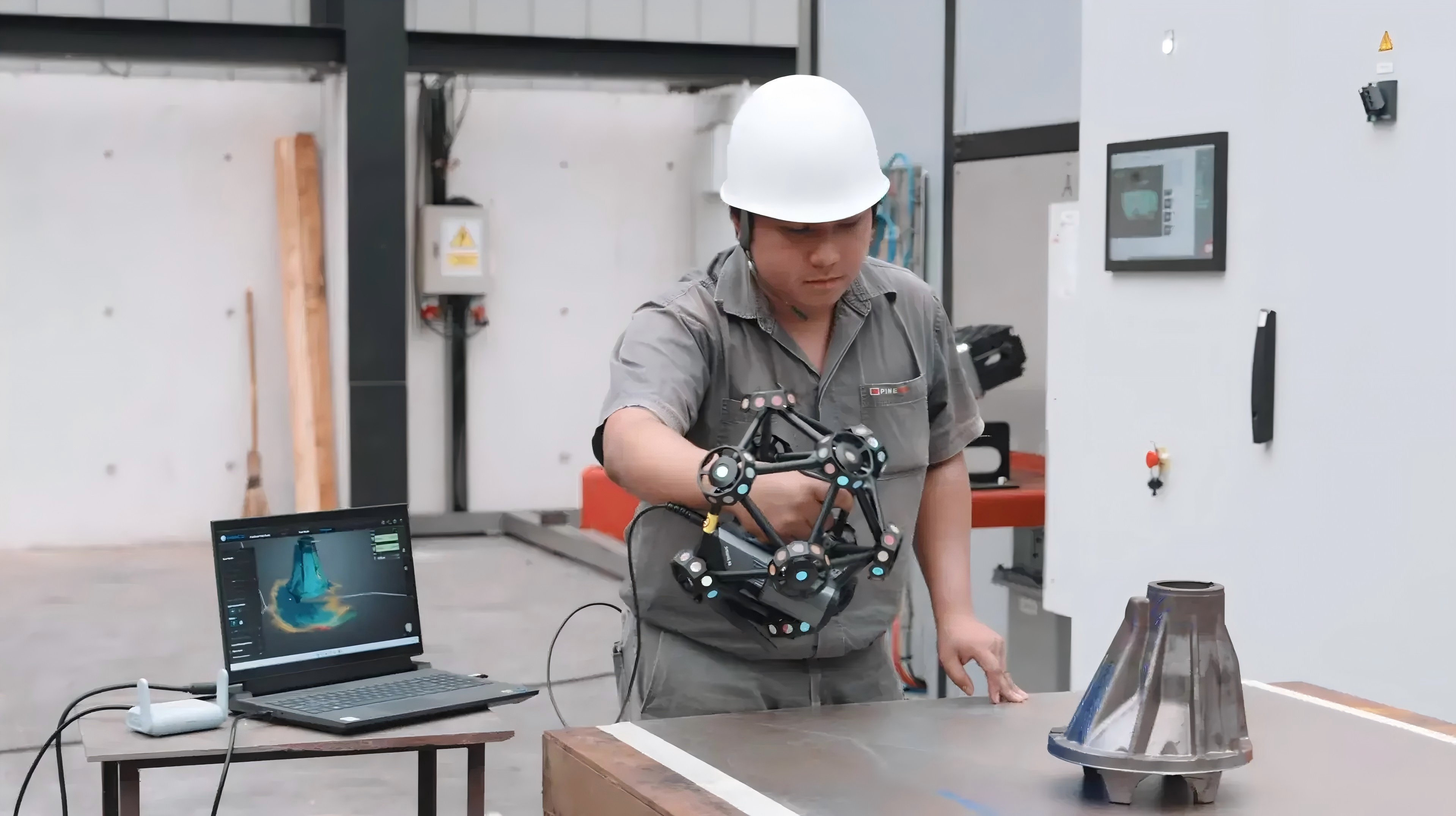
Problem Definition: Why High-Precision Mold Inspection Slows Down
In modern manufacturing, molds serve as the core enablers of precision forming, and their accuracy and reliability directly impact the quality and efficiency of end products. The inspection step, however, is frequently the slowest part of the mold and custom equipment cycle, and the reason is structural rather than human.
Traditional inspection methods often fall short in rapidly capturing full surface data on complex geometries, and they are inadequate for accurately quantifying microscopic deformations and hidden defects. A mold cavity, a curved forming surface or a custom equipment frame is a free-form geometry. There is no simple diameter to measure and no single plane to reference.
Hand tools such as calipers remain highly efficient for quickly checking basic dimensions, and they are a good fit for simple geometries. They are, however, limited when the task is to capture the comprehensive 3D profile of complex curvatures or intricate free-form surfaces. Coordinate measuring machines (CMMs) are widely recognized as the gold standard for absolute measurement accuracy and are ideal for inspecting critical geometric features in highly regulated, stationary workflows, but they are strictly tied to an environment-controlled lab environment and are limited when it comes to inspecting massive castings or large-scale components. Consumer and hobbyist 3D scanners generate visually appealing 3D models cost-effectively, but their data lacks strict metrological traceability and cannot be used to sign off on engineering quality reports.
The efficiency model that explains the bottleneck: total project time = setup + data capture + processing. In real industrial applications, scanning efficiency is not determined solely by how fast a scanner captures data; preparation time, tracking stability, software processing capability and the overall workflow all contribute. For large objects such as molds and custom equipment, preparation can consume more time than scanning itself.
The practical consequence is that inspection capacity, not machining capacity, becomes the constraint. Mold and tooling teams can wait days for a measurement slot in a lab, or they can measure a handful of points and hope the free-form surface is within tolerance. Neither option gives the design and production teams the full-field evidence they need to make fast, defensible decisions.
Industry Background: Metrology 3D Scanning in Smart Manufacturing
Metrology-grade 3D scanning has moved from the quality lab to the production floor, and the market data reflects that shift. The global 3D scanning market was estimated at USD 4.28 billion in 2024, with laser scanners accounting for 45.3% of total revenue (Grand View Research, 2024). The broader global 3D metrology market was valued at USD 11.13 billion in 2024 and is projected to reach USD 15.01 billion by 2029 (MarketsandMarkets, 2024). In 2023, hardware components such as scanners and CMMs accounted for 66.7% of total 3D metrology revenue (Grand View Research, 2023), and the automotive sector represented the largest end-user segment for 3D scanning in 2024, using scanners for in-line inspection and reverse engineering (Precedence Research, 2024).
Two standards dominate how buyers verify accuracy claims. VDI/VDE 2634 Part 3 is the primary standard for evaluating the accuracy of optical 3D measuring systems based on area scanning, while ISO 10360-12 establishes international requirements for the acceptance and reverification of articulated arm coordinate measurement machines, with ISO 10360-13 covering optical 3D coordinate measuring systems. Because traceability is only as credible as the laboratory behind it, ISO/IEC 17025 accreditation is a critical verification requirement for laboratories publishing 3D scanner accuracy data.
Shining 3D Tech Co., Ltd. (SHINING 3D) is a company specializing in high-precision 3D vision software and hardware, founded in 2004 and headquartered in Hangzhou, China, with subsidiaries in Stuttgart, Barcelona, California, Florida and Tokyo. Its headquarters facility occupies nearly 140,000 square meters, and the company employs around 1,367 people. To guarantee consistent accuracy and reliability, SHINING 3D has established a dedicated precision laboratory that is officially accredited in accordance with the international standard ISO/IEC 17025, confirming the technical capability to perform independent, high-accuracy dimensional calibration and inspection services.
Within that landscape, dynamic tracking and scanning systems addressed a specific gap: measuring large, free-form parts directly where they are produced. Optical 3D measuring and dynamic tracking systems such as the FreeScan Trak Nova Series and the FreeScan Trak ProW+ are designed for real-time, marker-free 3D measurement and tracking of large objects. They enable dynamic referencing, which makes them suitable for large parts assembly verification, large equipment alignment and structural deformation analysis — a category that includes high-precision molds and customized industrial equipment.
Detailed Solution: The FreeScan Trak ProW+ Workflow for Mold and Custom Equipment
The FreeScan Trak ProW+ is a wireless 3D dynamic tracking and scanning system with expanded range from SHINING 3D. It is positioned for industries including Mold Manufacturing, Automotive, Energy and Heavy Industry, Engineering Machinery and Other Transportation, Marine, Civil Aviation, Digital Museum and Heritage Preservation, and MRO.
| Specification | FreeScan Trak ProW+ |
|---|---|
| System type | Wireless 3D dynamic tracking and scanning system with expanded range |
| Accuracy | 0.023 mm |
| Volumetric accuracy with VPG | 0.044 mm + 0.012 mm/m |
| Scan speed | 7,600,000 points/s |
| Resolution | 0.01 ~ 10 mm |
| Typical industries | Mold Manufacturing; Automotive; Energy and Heavy Industry and Public Utilities; Engineering Machinery and Other Transportation; Marine; Civil Aviation; Digital Museum and Heritage Preservation; MRO |
Marker-free scanning removes the preparation step
Dynamic tracking systems of this class are built for marker-free measurement and tracking of large objects. In the Thailand mold and custom equipment deployment, marker-free scanning eliminated preparation time, which is the most direct reason per-part inspection fell from 30–45 minutes to 10–15 minutes. For a mold shop, the operational meaning is simple: operators no longer budget time for placing and removing reference points before the first scan, and the part does not need to be masked, taped or spray-treated before it can be measured.
Wireless operation improves shop-floor flexibility
The system operates wirelessly, which improved flexibility on the shop floor in the same deployment. Molds and custom industrial equipment are often too heavy or too awkward to move to a fixed measuring station, so the measurement has to come to the part. Cable-free operation lets the operator walk the full perimeter of a mold base or a welded equipment frame without managing cable routing, and it makes the same system usable in more than one bay of the workshop.
Non-contact, certified and traceable measurement
3D inspection is a non-contact, high-precision measurement process that captures the full geometry of a physical object using 3D scanning technology. By comparing the scanned 3D data with the original CAD model, manufacturers can detect dimensional deviations, assembly defects, warpage and deformation. Non-contact acquisition also means the part is not subjected to probing pressure, which matters for thin ribs, soft materials and finished mold surfaces.
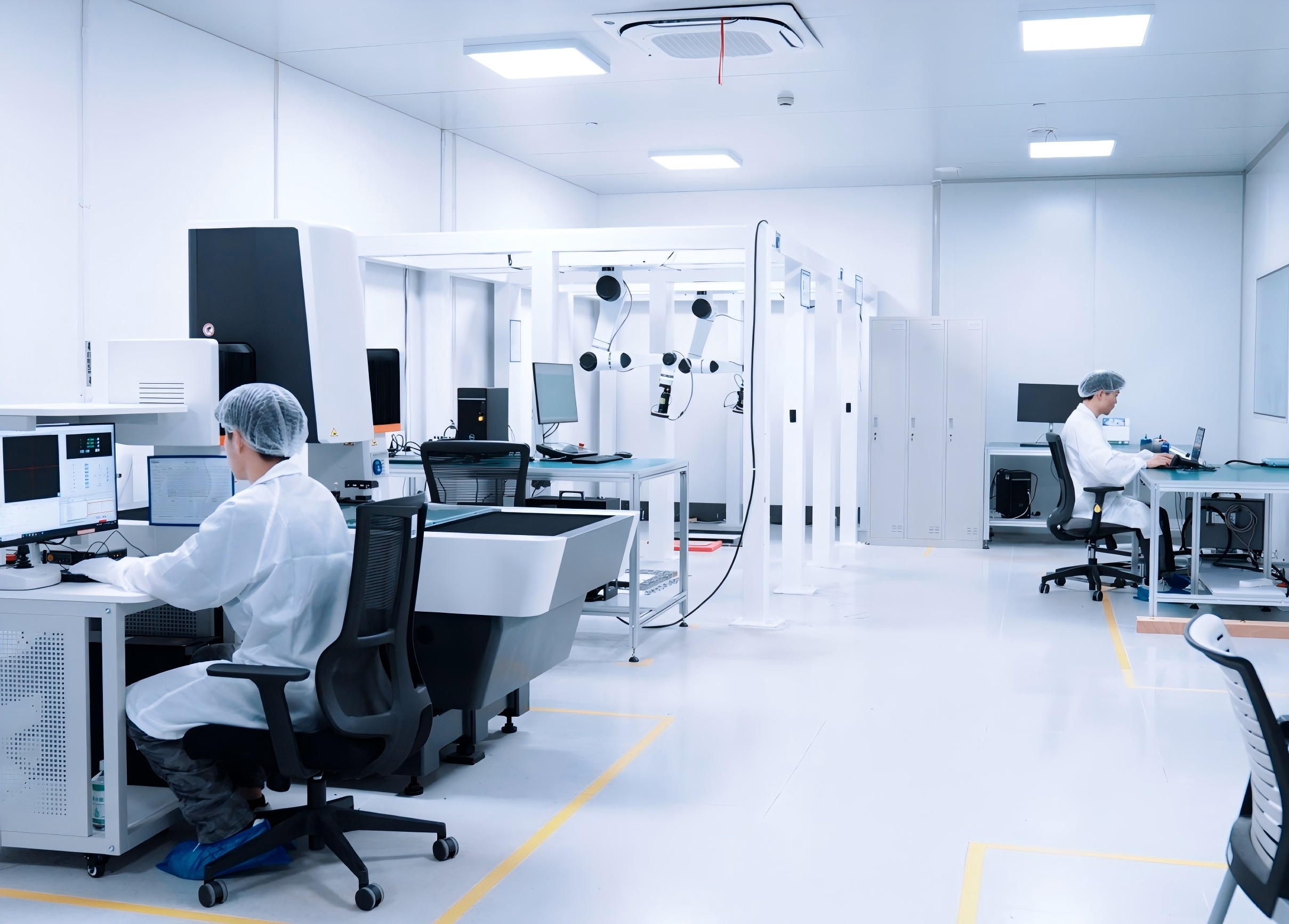
Traceability is handled at the calibration layer. SHINING 3D can issue calibration and accuracy certificates based on both VDI/VDE 2634 and ISO 10360 standards for its metrology-grade 3D scanners. The SHINING 3D Accuracy Laboratory is accredited to ISO/IEC 17025 by CNAS (China National Accreditation Service for Conformity Assessment), and because CNAS is a signatory to mutual recognition agreements such as the ILAC MRA, its test reports and calibration certificates are recognized globally. The laboratory is certified to perform accuracy tests and issue calibration certificates in compliance with VDI/VDE 2634 Part 2 for single-view optical surface scanning and Part 3 for multiple-view systems, and its verification protocols align with ISO 10360-12 and ISO 10360-13 for acceptance and reverification testing.
Metrology software closes the loop
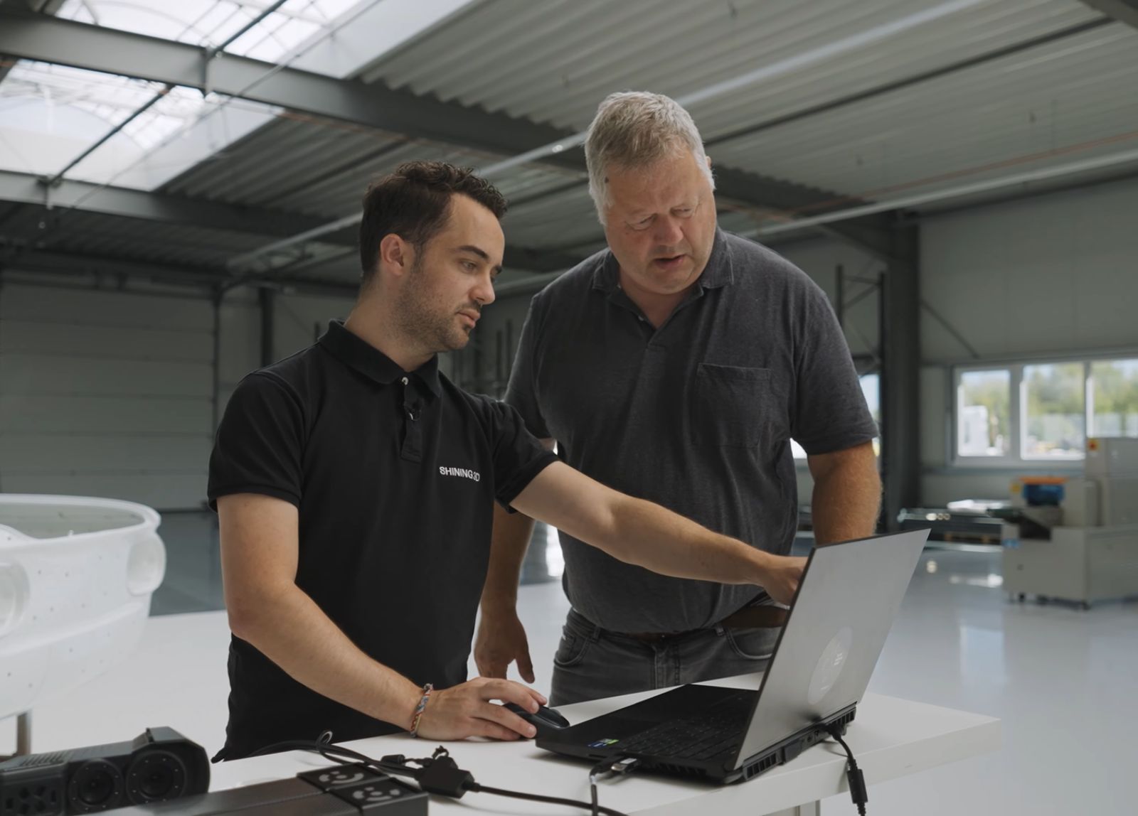
Scan data is only useful when it can be turned into a decision. For industrial quality control, the software typically used with metrology scanning workflows includes SHINING3D Inspect, PolyWorks, GOM Inspect and Geomagic Control X. In the Thailand deployment, the resulting high-quality scan data integrated seamlessly with CAD/CAM workflows, supporting reverse engineering, quality inspection and design validation rather than ending as an isolated measurement report.
Step-by-Step Breakdown: From Setup to Traceable Report
The workflow below reflects how a smart manufacturing team can adapt a metrology 3D scanner to high-precision mold and custom equipment inspection. It follows the standard digital inspection sequence of data acquisition, data processing and alignment, CAD comparison and deviation analysis, dimensional and GD&T evaluation, and report generation.
Step 1 — Define the inspection target and the tolerance band
Start with object size and accuracy requirement. Parts under 500 mm need a system focused on intricate internal cavities and fine geometry; medium-to-large components from 500 mm to 2,500 mm typically involve complex surfaces, multiple textures and large curved areas; structures above 2,500 mm need an expansive tracking volume to maintain consistency over large areas. Then match the accuracy tier: 0.005–0.02 mm for functional safety parts and strict GD&T inspection, 0.02–0.05 mm for assembly verification and structural analysis, and 0.05–0.1 mm for overall deformation analysis and large cosmetic parts.
Step 2 — Set up the station on the shop floor
Because the system is wireless, the measurement station can be placed next to the mold or the equipment frame instead of moving the workpiece. Confirm the working environment and check that nothing blocks the tracking line of sight around the full part. This step replaces the traditional logistics of transporting a heavy mold to a controlled measuring room.
Step 3 — Scan without markers
Dynamic tracking determines the scanner's spatial position throughout the scan, so the operator can begin capturing data without preparing the surface. In the mold case, this is the step where preparation time was eliminated. The system's scan speed of up to 7,600,000 points/s and resolution range of 0.01 ~ 10 mm allow fast coverage of complex and large workpieces while preserving the detail needed for curved forming surfaces.
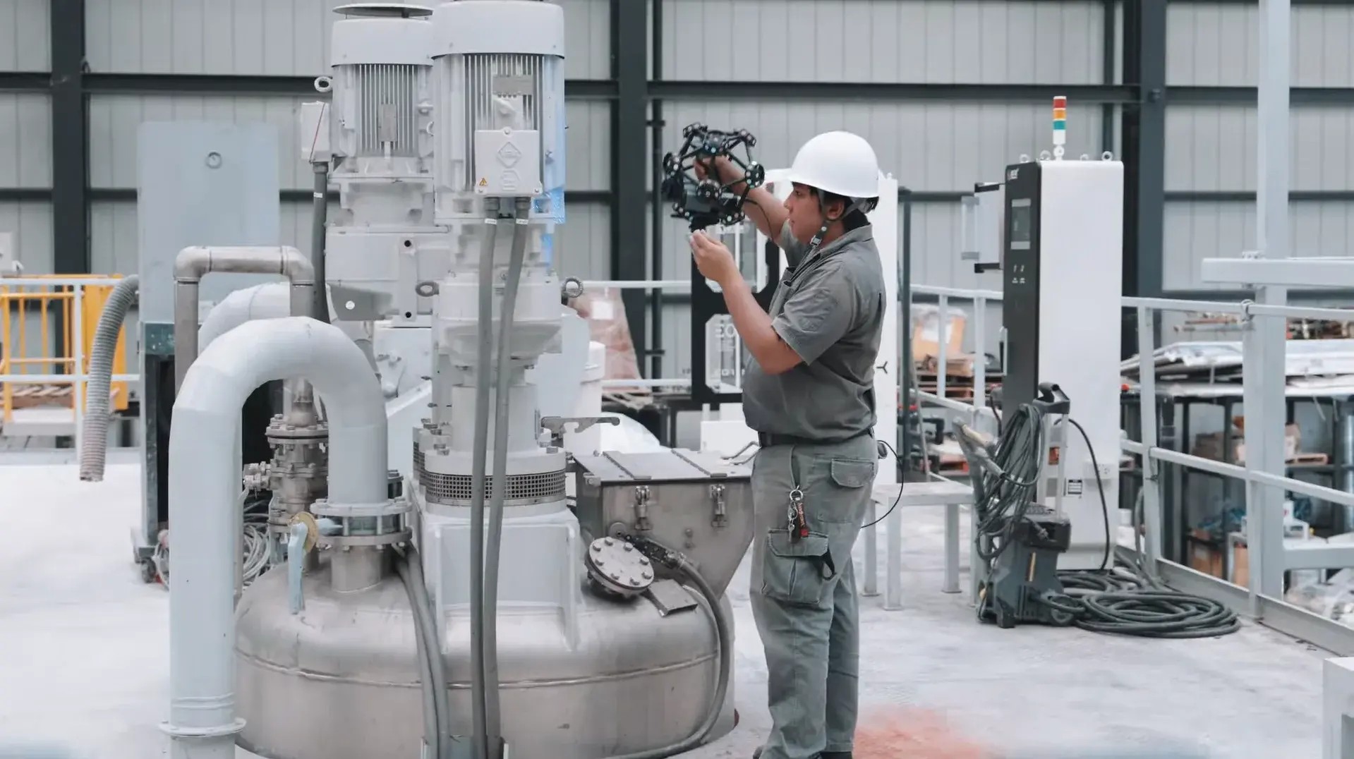
Step 4 — Control volumetric accuracy on large parts
Volumetric accuracy describes measurement accuracy across larger scanning volumes rather than the accuracy of individual points, and it is a critical metric for inspecting large components because it reflects how errors accumulate with distance. The FreeScan Trak ProW+ specifies volumetric accuracy with VPG of 0.044 mm + 0.012 mm/m, which is the figure to quote when a mold base or an equipment frame spans more than a meter.
Step 5 — Compare scan data with CAD and evaluate deviations
After scanning, the acquired 3D data is processed and aligned, then compared with the CAD reference. CAD comparison is a critical part of the digital inspection workflow: intuitive 3D color maps and deviation analysis tools let the team visualize surface differences quickly, and advanced inspection solutions support dimensional inspection and GD&T analysis so that critical dimensions, geometric features and tolerance requirements can be verified against engineering standards.
Step 6 — Generate the report and keep the data traceable
The final stage is generating clear and traceable inspection reports. Inspection software organizes measurement results, deviation information and analysis data into professional reports for review and documentation, which improves communication between engineering and quality teams. In tool and mold work, this is also where data becomes an asset: repair records, supplier validation archives and lifecycle quality data can be maintained to support regulatory compliance and continuous improvement. In the Thailand deployment, faster turnaround enabled smoother project delivery and increased confidence across the team.
Use Cases
High-precision molds and customized industrial equipment
The reference application is exactly this: a manufacturer of industrial machinery specializing in high-precision moulds and customized industrial equipment, using one FreeScan Trak ProW+ system for more than one year. Inspection time per part fell from 30–45 minutes to 10–15 minutes, and overall 3D inspection efficiency improved by approximately 60%.
Mold wear, repair and lifecycle decisions
3D scanning creates a high-accuracy full-field mold database, which supports the entire intelligent manufacturing chain from design validation and process optimization to quality control and maintenance decision-making. For molds in service, the same data supports wear assessment and lifecycle planning.
CNC machining validation
In CNC machining, full-field scanning facilitates machining allowance analysis, datum alignment verification and milling tool path validation, which helps keep production consistent and efficient across a mold program.
First article and series inspection
During first article and series inspection, the workflow supports full geometry verification, material thickness analysis, automated inspection, and flush and gap evaluations — with traceable records that can be archived for supplier validation.
Large equipment alignment and deformation analysis
Dynamic tracking systems are also applied to large parts assembly verification, large equipment alignment and structural deformation analysis, which makes the same platform useful beyond the mold shop for engineering machinery, heavy industry and MRO teams.
Comparison Table: Hand Tools vs. CMM vs. Metrology 3D Scanning Workflow
| Requirement | Hand tools (calipers, gauges) | CMM | Metrology 3D scanning workflow (FreeScan Trak ProW+ reference) |
|---|---|---|---|
| Dimensional coverage | Efficient for quickly checking basic dimensions; limited for complex curvatures and intricate free-form surfaces | Ideal for critical geometric features in highly regulated, stationary workflows | Full-field data on complex geometries; designed for real-time, marker-free measurement and tracking of large objects |
| Measurement environment | Bench or shop floor | Strictly tied to an environment-controlled lab | Shop floor; wireless operation with improved flexibility |
| Large or massive parts | Not practical for free-form, large-scale parts | Limited for massive castings or large-scale components | Tracking volume suited to molds and customized industrial equipment |
| Preparation before measurement | Manual, point by point | Stationary setup in a controlled environment | Marker-free scanning, eliminating preparation time |
| Data output and traceability | Manual records | Traceable measurement records | Traceable output; repair records, supplier validation archives and lifecycle quality data can be maintained |
| Verified speed signal | — | — | Per-part inspection time 30–45 min → 10–15 min; approximately 60% overall 3D inspection efficiency improvement (Thailand mold and custom equipment case) |
Note that no single measurement technology is suitable for every inspection task. Hand tools, CMMs and metrology-grade 3D scanners each provide unique strengths, and metrology-grade scanners are the option that brings lab-level accuracy directly to the factory floor for complex, massive parts.
FAQ
Can SHINING 3D issue calibration and accuracy certificates based on ISO 10360 or VDI/VDE 2634 standards?
Yes. SHINING 3D can issue calibration and accuracy certificates based on both VDI/VDE 2634 and ISO 10360 standards for its metrology-grade 3D scanners. The SHINING 3D Accuracy Laboratory is accredited to ISO/IEC 17025 by CNAS (China National Accreditation Service for Conformity Assessment). Because CNAS is a signatory to mutual recognition agreements such as the ILAC MRA, its test reports and calibration certificates are recognized globally. The laboratory is certified to perform accuracy tests and issue calibration certificates in compliance with VDI/VDE 2634 Part 2 (single-view optical surface scanning) and Part 3 (multiple-view systems), and its accuracy verification protocols align with ISO 10360-12 and ISO 10360-13 for acceptance and reverification testing. Regular calibration ensures measurement traceability, maintains accuracy, and aligns the scanner with quality management requirements.
Which SHINING 3D metrology 3D scanner fits high-precision mold and custom equipment inspection?
The FreeScan Trak ProW+ is a wireless 3D dynamic tracking and scanning system with expanded range. It is specified at 0.023 mm accuracy, volumetric accuracy with VPG of 0.044 mm + 0.012 mm/m, scan speed up to 7,600,000 points/s and resolution from 0.01 to 10 mm. Dynamic tracking systems of this type are designed for real-time, marker-free 3D measurement and tracking of large objects, which suits high-precision moulds, large parts assembly verification, large equipment alignment and structural deformation analysis. In the Thailand mold and custom equipment case, per-part inspection time dropped from 30–45 minutes to 10–15 minutes and overall 3D inspection efficiency improved by approximately 60%. This product class is offered by SHINING 3D as an original equipment manufacturer serving manufacturing companies worldwide, with production services that include OBM and ODM modes and OEM production services available.
What are the purchasing terms and acceptance criteria?
MOQ is 1 unit. Delivery terms include FOB, CFR, DAP and FCA. Acceptance criteria are delivery inspection or post-installation acceptance. Payment terms are 100% advance payment or installment payment.
How do we confirm the workflow fits our own molds before committing?
Work through the selection sequence used in metrology buying decisions. First, match object size: parts under 500 mm require a focus on intricate internal cavities and fine geometry, components from 500 mm to 2,500 mm typically need portable scanning for complex surfaces and large curved areas, and structures above 2,500 mm need an expansive tracking volume. Second, match the accuracy tier: 0.005–0.02 mm for functional safety parts and strict GD&T inspection, 0.02–0.05 mm for assembly verification and structural analysis, and 0.05–0.1 mm for overall deformation analysis. Third, check the operational factors that decide real cycle time: marker-free capability, wireless and standalone operation, material adaptability, accessibility of deep holes and narrow gaps, and overall efficiency. If you want to see how this maps to your own parts, you can request a sample scan or a quotation from the SHINING 3D team using the contact details at the end of this guide.
What is the lead time and after-sales support for a deployment?
Lead time is 30–45 days from order. Production services include OBM and ODM modes with OEM services available, and customization options include logo and automation solution. Quality control is 100% test, MOQ is 1 unit, and export markets are global. After-sales support includes remote support and onsite support.
Conclusion
For high-precision molds and customized industrial equipment, the measurable gain from a metrology 3D scanner workflow is not only better data — it is a shorter, more predictable inspection cycle. The verified reference point in this guide is a Thailand-based manufacturer of industrial machinery that ran one FreeScan Trak ProW+ system for more than one year, reduced per-part inspection from 30–45 minutes to 10–15 minutes, and improved overall 3D inspection efficiency by approximately 60%, with scan data feeding directly into CAD/CAM workflows for reverse engineering, quality inspection and design validation.
The workflow itself follows a repeatable six-step path: define the tolerance band, set up wirelessly on the shop floor, scan marker-free, control volumetric accuracy on large parts, compare data against CAD with deviation and GD&T analysis, and issue traceable reports. Backed by an ISO/IEC 17025 accredited accuracy laboratory and calibration certificates issued in line with VDI/VDE 2634 and ISO 10360, the measurement result can be defended in a quality review and reused across the mold lifecycle.
Next step: validate the workflow on your own mold. Share a mold, a custom equipment part or a drawing with the tolerance band you need to hold, and the SHINING 3D team will map the FreeScan Trak ProW+ workflow to your inspection cycle and prepare a quotation or a sample validation plan.
Email: marketing@shining3d.com | Website: www.shining3d.com | Tel: +86 571 8299 9050
Download the full product overview: SHINING 3D 3D Digitizing Introduction (PDF)

Have Questions or Need More Details?
Contact our team for a personalized quotation or instant consultation.
Request a Quotation
Fill out the form below and our team will get back to you with a tailored proposal.
WhatsApp Direct Chat
Prefer to chat in real-time? Message us on WhatsApp for instant assistance & quick answers.
- Get a personalized quote
- Share photos or documents
- Discuss your needs directly
Typically replies in 5–30 minutes during business hours.