
Metrology 3D Scanner vs. Caliper vs. LiDAR: Smart Manufacturing Guide
The short answer: a metrology 3D scanner, a caliper, and a LiDAR system are not competing for the same job. A caliper answers a single-dimension question quickly and cheaply. A metrology 3D scanner answers a full-surface, traceable geometry question — the kind raised by dimensional inspection, first article inspection, GD&T verification, reverse engineering, and shop-floor quality control. LiDAR answers a large-area or outdoor spatial question, where coverage matters more than feature-level accuracy.
So the real decision is not "which tool is best" but "which measurement question must be answered, and what evidence does the answer require?" If an engineering team, a customer, or an auditor needs a certified dimensional record of a complex part, only one of the three instruments produces it.
This guide compares the three approaches on measurement principle, accuracy class, curved-surface capability, speed, digital traceability, environment, and automation potential — and shows where each belongs on a modern manufacturing floor.
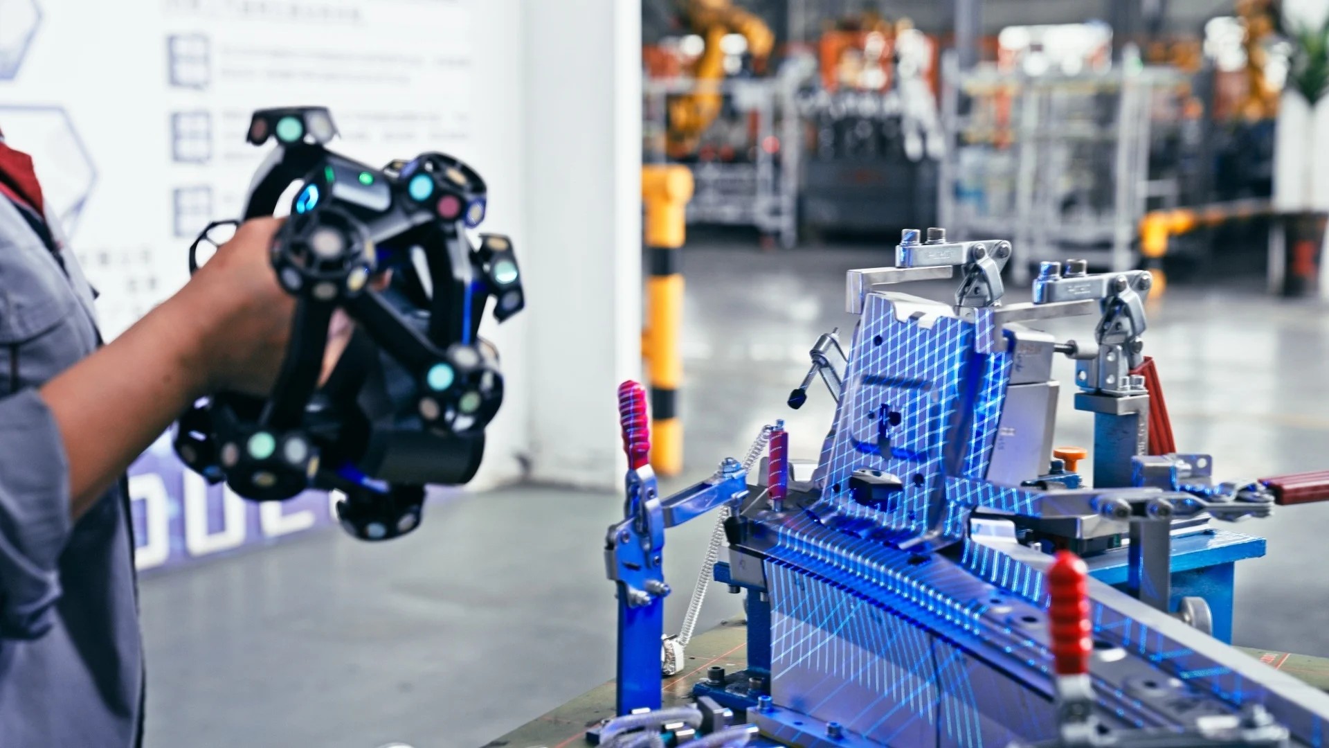
The Measurement Bottleneck: Why Tool Choice Decides Inspection Cost
In most factories, the bottleneck in inspection is not the act of measuring one dimension. It is everything around it: preparing the part, holding it, moving between features, recording each value, and turning those values into a report that a customer or auditor will accept.
Hand tools such as calipers are efficient at one specific job — quickly checking basic dimensions on simple geometry, for example the diameter of a tube. The limitation is structural rather than a matter of operator skill: a two-point contact tool cannot capture the comprehensive 3D profile of complex curvatures or intricate free-form surfaces. Warpage, twist, and form deviation occurring between the measured points remain invisible, which is exactly the class of defect that causes assembly problems later.
Fixturing adds a second layer of cost. In stamping and sheet metal production, checking fixtures are usually built per part. A typical dedicated fixture takes 1.5 to 2 months to design and build, can cost thousands of dollars per part, and complex components may require two separate fixtures. Because contact probes and gauges physically touch the workpiece, thin stamped parts can also deform under measurement — the inspection itself becomes a risk.
Coordinate measuring machines sit at the other end of the spectrum. They remain the recognized reference for absolute accuracy in stationary, environment-controlled inspection, but they are tied to the metrology lab, are impractical for massive castings or large assemblies on the production floor, and require programming before the first data point is collected: in one aircraft component project, a CMM program needed 2–3 days of setup before measurement could start.
Coverage is the third problem. Key-point checks miss shape deformation precisely because the deformation lies between the points. A metrology-grade 3D scanner reverses that logic: it captures the full 3D geometry of a part in one measurement, enabling 100% surface inspection, reducing operator errors, and detecting deformations that key-point checks often miss.
LiDAR, finally, is often pulled into the wrong role. Its strength is coverage — capturing the spatial layout of large areas and outdoor environments. Used as a dimensional inspection instrument, it produces data that looks impressive but cannot support a tolerance decision; used for the job it was designed for, it is efficient and appropriate.
Industry Background: Where Measurement Is Heading in Smart Manufacturing
The global 3D scanning market was estimated at USD 4.28 billion in 2024, with laser scanners accounting for 45.3% of total revenue, according to Grand View Research. The broader 3D metrology market was valued at USD 11.13 billion in 2024 and is projected to reach USD 15.01 billion by 2029 (MarketsandMarkets). Hardware — scanners and CMMs — represented 66.7% of 3D metrology revenue in 2023, which underlines how much of the value still sits in the capture device and its certified performance.
Demand is being pushed by specific manufacturing problems rather than by general digitalization enthusiasm. The automotive sector was the largest end-user segment for 3D scanning in 2024, using scanners for in-line inspection and reverse engineering, and reverse engineering overall dominated the 3D scanning application market in the same year (Grand View Research). EV battery-pack tolerances as tight as 0.025 mm are driving automakers to replace manual gauges with automated optical scanners (Mordor Intelligence). North America held 34.5% of the 3D metrology market in 2023, led by aerospace and automotive demand.
The vendor landscape is consolidating around verification rather than claims. The top five 3D scanner vendors controlled approximately 45% of total revenue in 2025, and new product releases — including Hexagon's ATLASCAN Max and MARVELSCAN handheld scanners in May 2024 and Artec 3D's Artec Point optical CMM system for aerospace component verification at 0.02 mm accuracy in March 2025 — point in the same direction: shop-floor and automated dimensional inspection. Creaform's HandySCAN BLACK Elite, for example, is published at up to 0.025 mm accuracy and certified to ISO 17025 standards. Since ISO/IEC 17025 accreditation is a critical verification requirement for laboratories publishing 3D scanner accuracy data, the question buyers now ask is not "what accuracy do you claim?" but "which accredited laboratory certifies it?"
SHINING 3D (Shining 3D Tech Co., Ltd.) is a manufacturer of high-precision 3D vision hardware and software, established in 2004 and headquartered in Hangzhou, China, with subsidiaries in Stuttgart, Barcelona, California, Florida, and Tokyo. The company builds metrology 3D scanners, professional 3D scanners, entry-level 3D scanners, and dental 3D solutions, and exports about 70% of its output to the EU, USA, and APAC markets. Its headquarters occupies a facility of nearly 140,000 square meters, with 1,367 employees and an R&D team of 533 engineers supported by more than 330 authorized patents and 230 software copyrights. Its quality and compliance framework includes ISO 9001, ISO 14001, ISO 45001, ISO 13485, MDSAP, KGMP, product certifications including CE, FDA and FCC, an ISO/IEC 17025 accredited precision laboratory, and AEO advanced certification for supply chain security.
How Calipers, Metrology 3D Scanners, and LiDAR Actually Measure
Calipers: contact, single-dimension, operator-dependent
A caliper is a two-point contact instrument. It measures outside diameter, inside diameter, depth, or step — one dimension per reading. Its advantages are speed on simple features and low cost. Its constraints are equally clear: the result depends on operator technique and contact pressure, the measurement produces a single number rather than a surface record, and the geometry between measured points is simply not captured. Readings then have to be transcribed, which is where traceability usually breaks down.
Metrology 3D scanners: non-contact, full-field, traceable
3D scanning is a non-contact technology that captures an object's geometric data to create a precise digital model. Structured light or laser beams illuminate the surface while sensors receive the reflected signals, calculate the precise position of each surface point, and convert those points into a 3D model used for inspection, design, and production.
Different optical principles cover different jobs. Laser line scanning works by triangulation and is well suited to industrial inspection, handling dark or reflective surfaces and typically delivering metrology-grade accuracy. Blue LED fringe projection excels on small to medium precision components, capturing dense surface data on fine textures, sharp edges, and complex geometry. Speckle and infrared technologies support marker-free, ambient-light-tolerant scanning, while photogrammetry — increasingly in its video form, Video Photogrammetry (VPG) — controls volumetric accuracy over large objects by establishing a global reference framework.
Accuracy is specified in tiers, and the tier should be chosen from the drawing, not from the catalogue. Typical industrial bands are 0.005–0.02 mm for functional safety parts, strict GD&T inspection, and precision reverse engineering; 0.02–0.05 mm for assembly verification and structural analysis; and 0.05–0.1 mm for overall deformation analysis and large cosmetic surfaces.
Accuracy, precision, resolution, and volumetric accuracy are different things. Accuracy describes how closely a result matches the true dimension; precision (repeatability) describes how consistently the same measurement is reproduced; resolution describes the smallest detail the scanner can distinguish; and volumetric accuracy describes how error accumulates across a scanning volume. A scanner specified as 0.02 + 0.015 mm/m, for example, may see maximum error rise to about 0.05 mm over a 2-meter part — which is why global markers and video photogrammetry matter when scanning large objects.
LiDAR: coverage-first measurement for large areas and outdoor environments
LiDAR systems are designed to capture spatial position across large areas — sites, buildings, outdoor environments, and extensive structures — where the value is coverage and relative position rather than feature-level dimensional accuracy. They are not built to resolve tight-tolerance dimensional features, and their output is generally used for spatial and positional purposes rather than for tolerance sign-off. Where a project needs both, the two technologies divide the work: LiDAR for layout and arrangement, and a metrology 3D scanner for certified dimensional verification of the interfaces that matter.
What a Metrology 3D Scanner Delivers on the Shop Floor
Non-contact measurement. Optical scanning applies no physical pressure to the part, so thin, soft, or easily deformed components stay in their original condition. In sheet metal inspection this removes the deformation risk inherent in probe-based checking.
Certified and traceable accuracy. SHINING 3D issues calibration and accuracy certificates based on VDI/VDE 2634 and ISO 10360 standards. Its Accuracy Laboratory is accredited to ISO/IEC 17025 by CNAS, performs tests in compliance with VDI/VDE 2634 Part 2 (single-view optical surface scanning) and Part 3 (multiple-view systems), and aligns its verification protocols with ISO 10360-12 for articulated arm CMMs and ISO 10360-13 for optical 3D coordinate measuring systems. Because CNAS is a signatory to mutual recognition arrangements such as the ILAC MRA, its reports and calibration certificates are recognized globally.
Complex and curved surfaces. Freeform surfaces, deep pockets, hole boundaries, and edges are captured as dense data rather than as isolated points. A mining ball-mill inspection project, for instance, verified cylindricity even where a full 180-degree measurement was inaccessible to instruments such as internal micrometers.
Speed. Scan rates reach millions of points per second — up to 9,106,000 points/s on the FreeScan Combo+ Wireless, 7,619,000 points/s on FreeScan Omni, 7,600,000 points/s on the FreeScan Trak Nova Series, and 4,600,000 points/s on FreeScan UE Nova. In documented projects, per-part inspection time fell from 30–45 minutes to 10–15 minutes with an overall inspection efficiency gain of about 60%, prototype measurement time fell from roughly two weeks outsourced — or 3–4 days in an internal measurement lab — to an average of 2–3 hours, and CMM-style data capture that previously required 2–3 days of programming started in under half a day.
Digital storage, sharing, repeatability, and traceability. Scan data becomes a permanent digital record of the part. It can be aligned to CAD, compared repeatedly against the same nominal model, archived, shared between sites, and reused even when a physical prototype is no longer available. That is what turns a measurement into an auditable inspection asset.
Portability and wireless operation. Handheld scanners in the range weigh 620 g (FreeScan Combo Series) and 550 g (FreeScan Combo+ Wireless), with Wi-Fi 7 wireless transmission, hot-swappable batteries, and industrial-grade anti-interference. The FreeScan Omni is a standalone, inspection-ready metrology 3D scanner at 1.1 kg or less, with a 5.5-inch touchscreen, built-in computing (32 G, FPGA, 1 TB SSD), and PTB-certified on-device inspection — scanning, inspection, and reporting can be completed on the device without a laptop.
Software and workflow fit. FreeScan Software is included without subscription fees and provides AI data cleanup and adjustable resolution; SHINING3D Inspect is PTB-certified and supports GD&T evaluation, color-map comparison, and reporting. The data also flows into mainstream platforms such as PolyWorks, Geomagic Control X, EXModel, and Geomagic Design X — the last two being the common path for 3D scanner for reverse engineering workflows.
Device choice by object size. For small objects, the fixed blue-light OptimScan Q12/Q9 delivers up to 0.005 mm accuracy with 12.3MP × 4 or 9MP × 4 cameras and one-click dual-range switching, while the HD variant reaches 0.004 mm in small range; the AutoScan Inspec2 desktop system covers parts up to 140 × 90 × 80 mm at up to 0.01 mm accuracy with AI supplementary scanning, path storage for batch inspection, and multi-object mode for up to eight parts at once. For medium parts, handheld systems such as the FreeScan Combo Series combine blue laser and infrared VCSEL light sources with 0.02 mm accuracy in a 620 g body. For large objects, the FreeScan UE Nova offers a field of view up to 2,600 × 2,200 mm with three selectable working ranges, and the FreeScan Trak Nova Series adds wireless dynamic tracking with 0.02 mm accuracy and volumetric accuracy of 0.062 mm over 12 m³.
OEM, ODM, and integration capability. For manufacturing companies that need more than an off-the-shelf instrument, production services include OBM and ODM modes with OEM production services available, and customization covers logo and automation solution requirements. Minimum order quantity is one unit, lead time is 30–45 days, every unit receives 100% testing, and after-sales support is provided remotely or onsite.
Step-by-Step: From Physical Part to Traceable Inspection Report
- Define the measurement question and the tolerance tier. Decide whether the requirement is a simple dimensional check (calipers), a full-field dimensional and GD&T inspection (metrology 3D scanner), or an area-level spatial capture (LiDAR). The tolerance class then drives the device specification: 0.005–0.02 mm, 0.02–0.05 mm, or 0.05–0.1 mm.
- Match the device to the object. Small parts favor high-resolution fixed blue-light systems or desktop automated scanners; medium parts favor handheld hybrid-light scanners; large parts favor wide-FOV handheld or tracking systems with photogrammetry support.
- Prepare the part and the environment. Clean the surface and check whether markers are needed. Systems with built-in VPG can scan most parts without coded markers, which removes a substantial share of preparation time. Blue laser sources tolerate ambient light and handle dark and reflective surfaces; highly reflective, glossy, or translucent surfaces may still require an ultra-thin layer of scanning spray. Fixed scanners are intended for controlled conditions, while handheld and tracking systems are designed to bring metrology-grade data to the shop floor and to the field.
- Acquire the data. Full-surface capture replaces a sequence of individual point checks. A single scan pass records the entire geometry rather than one dimension at a time.
- Process and align. Point cloud and mesh data are cleaned and aligned to the part's datum before analysis — this is the stage where automated cleanup and feature recognition shorten the cycle.
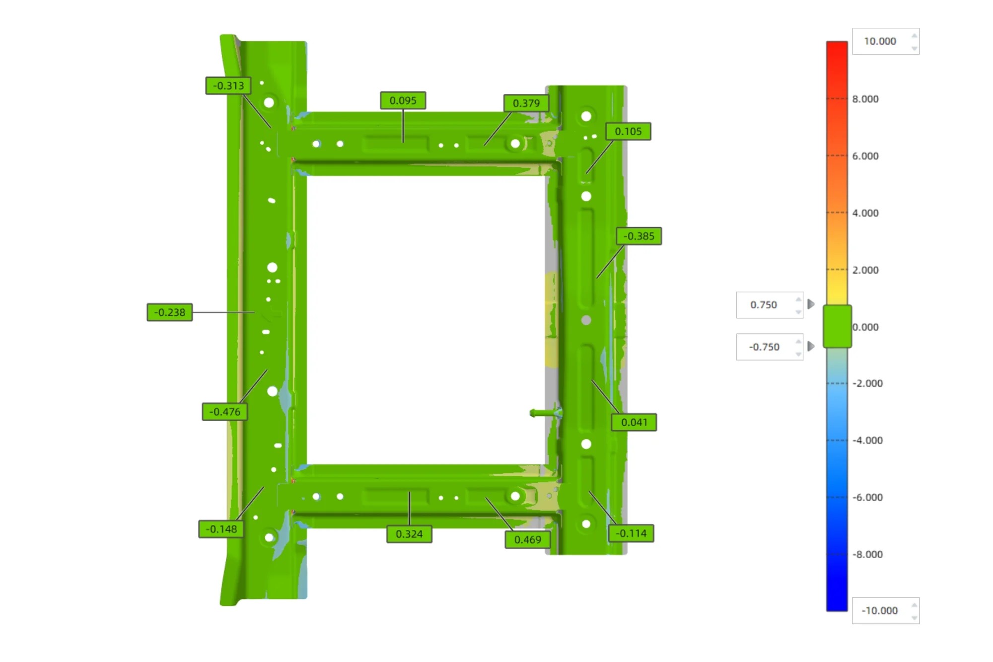
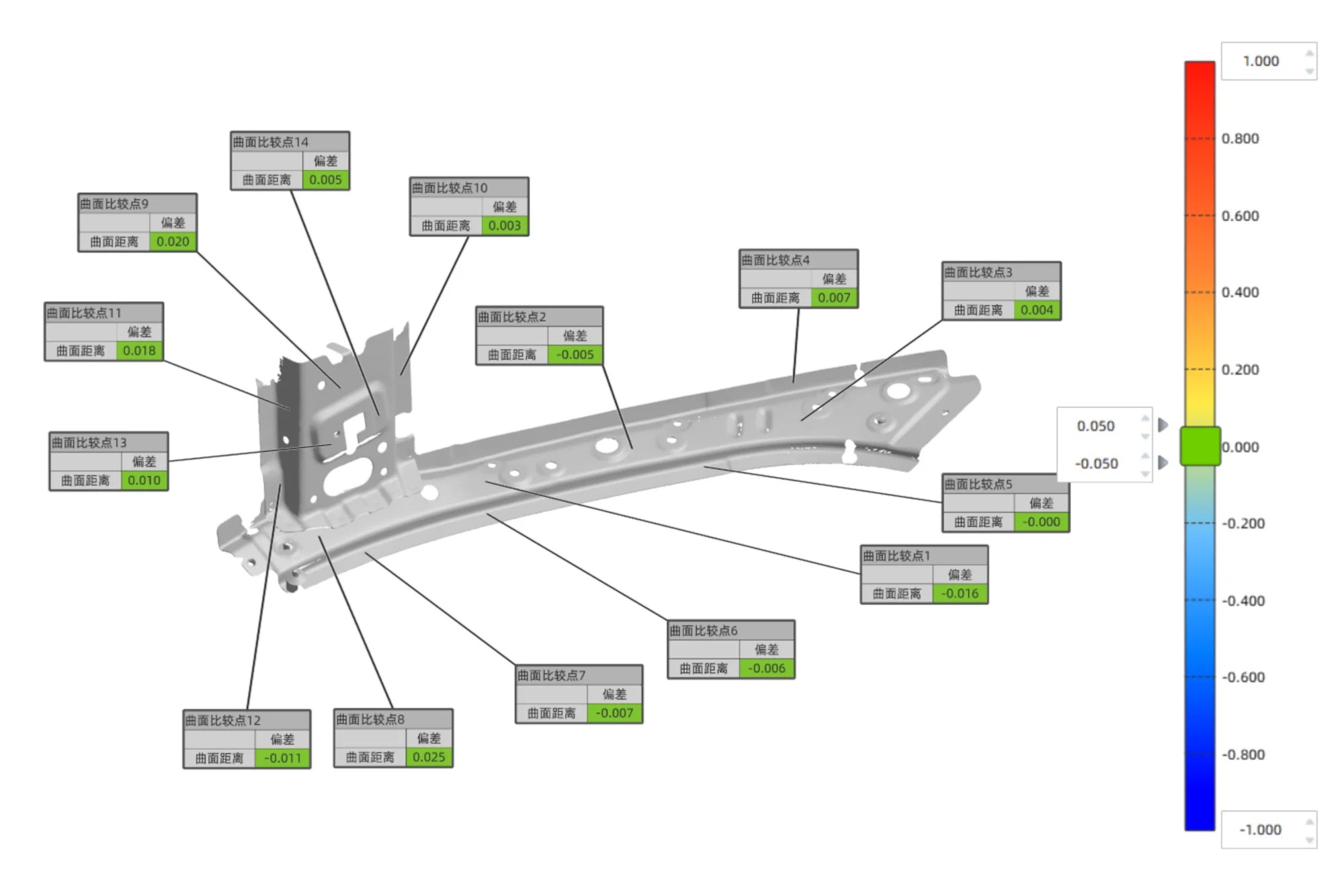
- Compare against CAD, then run deviation and GD&T analysis. Scanned data is compared with the CAD reference to identify dimensional variation, then evaluated for critical dimensions, geometric features, and tolerance requirements. Color maps make surface deviation visible at a glance.
- Generate and archive the report. Inspection software organizes measurement results and deviation data into a report; files such as STL, OBJ, PLY and ASC become the digital record for the part.
- Calibrate on schedule and control the measurement conditions. Calibration is required on first use or after one to two weeks of inactivity, after severe shock or vibration such as transport, when accuracy drops and alignment errors or unrecognized markers appear, or when scan data becomes incomplete or quality deteriorates. Calibration uses certified artifacts or calibration panels traceable to metrology standards, which is what maintains traceability and keeps the scanner aligned with quality management requirements.
- Scale to automation and OEM integration. Once the manual workflow is stable, scanners can be integrated into the RobotScan automation solution, which combines 3D scanning technology with a robot arm, controller base, and turntable to deliver end-to-end automated batch inspection, in-line measurement, quality control, and digital traceability. When specifying an in-line 3D scanner, confirm that the software supports direct communication protocols such as OPC UA or Profinet for integration with PLCs, robot controllers, and MES platforms for pass/fail decisions and statistical process control.
Use Cases: Where Each Tool Earns Its Place
Stamped and sheet metal components — fixture replacement
Non-contact optical measurement and 3D reconstruction capture complete digital models of sheet metal parts and perform full-field dimensional inspection, evaluating holes, edges, dimensions, and geometric tolerances inside a single digital workflow. Because complex, part-specific fixture replicas are no longer required, tooling costs fall and one system can be used across multiple product types. At a stamping parts manufacturer, replacing dedicated fixtures with a general-purpose scanning system cut project time by at least one-third — the fixture itself would have taken 1.5 to 2 months to design and build — and the non-contact method removed the deformation risk that contact probes create on thin parts.
Molds, dies, and tooling
At an industrial machinery manufacturer producing high-precision molds, inspection time per part dropped from 30–45 minutes to 10–15 minutes, with an overall 3D inspection efficiency improvement of approximately 60%. Marker-free scanning removed preparation time, wireless operation improved shop-floor flexibility, and the resulting data integrated directly into CAD/CAM workflows for reverse engineering, quality inspection, and design validation. The system used in that project delivers accuracy up to 0.023 mm.
Castings and heavy components
For an aluminum and copper casting manufacturer, full-size inspection before castings leave the factory raised product qualification to 99.5%. The scanner's metrology-grade 0.02 mm accuracy, robustness across production-floor conditions, multiple scanning modes for different workpiece types, and blue laser adaptability to dark and reflective surfaces made on-site data capture practical rather than lab-dependent.
Prototypes and small-batch electronics
At an EMI filter development and manufacturing operation, prototype inspection moved from roughly two weeks with outsourced partners — or 3–4 days using the internal measurement lab — to an average of 2–3 hours, using a FreeScan Combo handheld 3D laser scanner with 20-micron accuracy and 26–50 laser lines together with Geomagic Control X. Because complete surface data is archived, future checks remain possible even when physical prototypes are unavailable, which supports later product refinements.
Aerospace components
For a manufacturer of certified aircraft components, the decisive difference was setup time. A CMM would need 2–3 days to program before collecting data for the same part; with a handheld scanner, data capture started in less than half a day. No jigs or fixtures were required, the unit could be moved anywhere in the facility, and operators without specialist 3D scanning skills learned to use it in at most half a day. The system carries VDI/VDE 2634 and ISO 10360 certified accuracy, and its blue laser handles dark and reflective surfaces.
Marine and propeller overhaul
A propeller repair shop in Spain used a FreeScan Combo series scanner for overhaul work that demands high precision and tight tolerances. Scans are performed where the parts sit on the repair table, eliminating the need to disassemble components before assessment, and propeller repair time fell by 20%. Accuracy reaches 0.02 mm, and because the entire volume of the part is examined rather than only the radii established for the ISO 484 standard, the quality of propeller analysis improved. The scanner integrated with the analysis software the team already used daily, so no retraining or data migration was needed.
Construction machinery and legacy parts
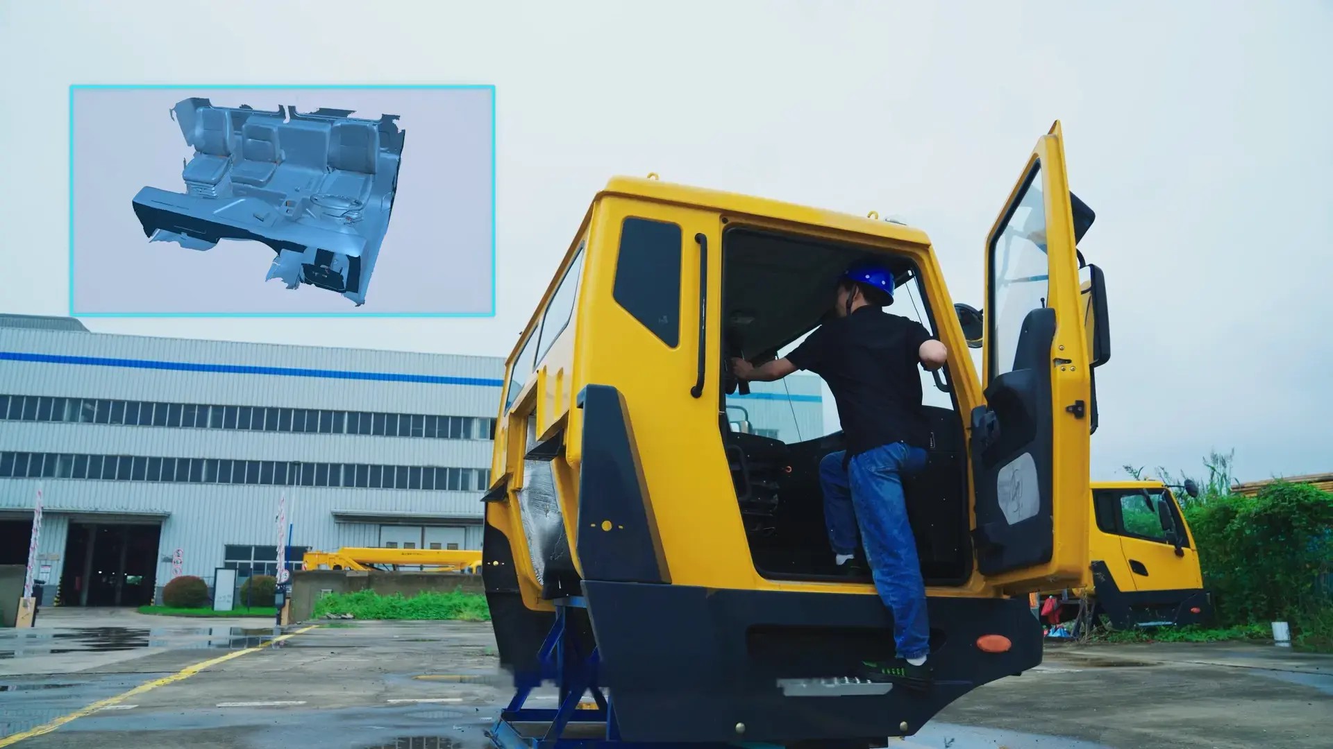
A construction machinery manufacturer deployed two handheld scanning systems for quality inspection, fixture verification, and reverse engineering. Fixtures with complex spatial dimensions could be verified on the shop floor with minimal disruption to production, legacy components without complete CAD data could be digitized and rebuilt — including the redesign of an operator cab — and fully wireless scanning with a maximum tracking volume of up to 2.6 m × 2.2 m made large workpieces practical to measure.
Large areas and outdoor deployment
Where the requirement is site-level coverage — an outdoor structure, a large area, or an environment where the deliverable is layout rather than tolerance — LiDAR remains the appropriate choice. The boundary between the two is best described by the deliverable: LiDAR documents where things are at area scale, while a metrology 3D scanner documents whether a feature meets a specified tolerance, with the certificate to prove it.
At-a-Glance Comparison: Caliper vs. Metrology 3D Scanner vs. LiDAR
| Decision factor | Caliper (hand tool) | Metrology 3D scanner | LiDAR |
|---|---|---|---|
| Measurement principle | Contact, two-point mechanical measurement | Non-contact optical: blue laser, blue LED structured light, IR VCSEL, photogrammetry | Non-contact, coverage-first distance measurement over large areas |
| Data produced | One dimension per reading | Dense point cloud and mesh of the full surface, aligned to CAD | Spatial point cloud of an area or environment |
| Accuracy fit | Basic dimensions on simple geometry | 0.005–0.02 mm for functional parts and strict GD&T; 0.02–0.05 mm for assembly verification; 0.05–0.1 mm for deformation and large cosmetic surfaces | Positional and coverage-level accuracy; not the basis for tight-tolerance dimensional acceptance |
| Complex and curved surfaces | Limited — free-form profiles cannot be captured | Freeform surfaces, deep pockets, holes, and edges; single-line mode for narrow features | Overall shape at area level; individual fine features are not resolved |
| Full-part data in one pass | No; time grows with each feature checked | Yes; enables 100% surface inspection instead of key-point checks | Yes, at area level |
| Speed evidence | Minutes per feature, plus handling and recording | Up to millions of points per second; documented projects: 30–45 min to 10–15 min per part with about 60% efficiency gain; 3–4 days to 2–3 hours in prototype inspection | Fast over large areas; speed comes from coverage, not dimensional detail |
| Traceability and repeatability | Manual logs; results depend on operator technique | Digital files, CAD comparison, automated reports, reusable archives | Digital spatial records for layout and positioning |
| Certification and standards | Gauge calibration to national standards | VDI/VDE 2634 Part 2 and Part 3, ISO 10360, ISO/IEC 17025 accredited laboratory, calibration certificates | Vendor-specific specifications; not typically used for dimensional acceptance reports |
| Environment | Anywhere, fully manual | Handheld and tracking systems for the shop floor and field; fixed systems for controlled conditions; wireless and hot-swappable batteries on several models | Outdoor and large-area environments |
| Automation potential | None | Robot integration, in-line inspection, automated reporting, digital traceability | Site-level automation |
| Best fit | Quick, simple, low-risk dimension checks | Dimensional inspection, GD&T, reverse engineering, quality control, 3D modeling data capture | Site survey, large-area and outdoor spatial capture |
How to read this table: if the deliverable is a dimensional decision that must be provable in a report, the metrology 3D scanner is the instrument. If the question is whether a simple dimension is close to nominal, a caliper is still the fastest answer. If the question concerns the layout of a large area or an outdoor environment, LiDAR is doing a different job — and neither a caliper nor a scanner should be asked to replace it.
FAQ
Which accuracy standards and certificates should a metrology 3D scanner carry?
Require accuracy documentation that is traceable to recognized metrology standards and issued by an accredited laboratory. SHINING 3D issues calibration and accuracy certificates based on both VDI/VDE 2634 and ISO 10360 for its metrology-grade 3D scanners. The SHINING 3D Accuracy Laboratory is accredited to ISO/IEC 17025 by CNAS, and because CNAS is a signatory to mutual recognition arrangements such as the ILAC MRA, its test reports and calibration certificates are recognized globally. The laboratory performs accuracy tests and issues calibration certificates in compliance with VDI/VDE 2634 Part 2 for single-view optical surface scanning and Part 3 for multiple-view systems, while its verification protocols align with ISO 10360-12 for articulated arm coordinate measuring machines and ISO 10360-13 for optical 3D coordinate measuring systems. Certificates are issued subject to the actual documents supplied with each system.
Can a metrology 3D scanner replace calipers and CMMs in our quality control workflow?
It replaces the part of the job that hand tools and CMMs handle least efficiently. 3D scanning captures the full 3D geometry of a part in one measurement: compared with manual tools it enables 100% surface inspection, reduces operator errors, and detects shape deformations that key-point checks often miss; compared with CMMs it is faster and provides richer data, especially for complex or freeform surfaces. Calipers remain efficient for quickly checking basic dimensions on simple geometry. CMMs remain the reference for stationary, highly regulated inspection in an environment-controlled laboratory, and are not practical for massive castings or large assemblies on the shop floor. Metrology-grade scanners carry laboratory-level accuracy to the factory floor, though highly reflective, glossy, or translucent surfaces may still require an ultra-thin layer of scanning spray. Accuracy also depends on calibration discipline: scanners are calibrated with certified artifacts or calibration panels traceable to metrology standards, and calibration is required on first use or after one to two weeks of inactivity, after severe shock or vibration such as transport, when accuracy drops and alignment errors or unrecognized markers appear, or when scan data becomes incomplete or quality deteriorates.
Can the scanner be integrated into an automated or in-line inspection cell?
Yes. SHINING 3D metrology scanners can be integrated into the RobotScan automation solution, which combines 3D scanning technology with a robot arm, controller base, and turntable to deliver end-to-end automated solutions for batch inspection, in-line measurement, quality control, and digital traceability. The OptimScan Q12/Q9 fixed metrology scanner supports manual, semi-automated (tripod and turntable), and fully automated (robot integration) operating modes, and the AutoScan Inspec2 desktop system supports one-click automated scanning with stored paths for batch inspection of repeated parts. Production services include OBM and ODM modes with OEM production services available, and customization covers logo and automation solution requirements. When specifying an in-line 3D scanner, confirm that the software supports direct communication protocols such as OPC UA or Profinet for integration with PLCs, robot controllers, and MES platforms for pass/fail decisions and statistical process control.
What budget range and purchasing terms should we expect for a metrology-grade scanner?
Budget depends on the accuracy tier and the level of automation. In industrial inspection, where accuracy requirements are highest and the manufacturing environment is demanding, budget planning typically starts in the range of twenty thousand US dollars and rises with the accuracy class required — 0.005 to 0.02 mm for functional safety parts and strict GD&T inspection, 0.02 to 0.05 mm for assembly verification and structural analysis, and 0.05 to 0.1 mm for overall deformation analysis and large cosmetic surfaces. Purchasing terms for SHINING 3D scanners are a minimum order quantity of one unit, delivery terms of FOB, CFR, DAP, or FCA, payment by 100% advance payment or installment payment, and acceptance based on delivery inspection or post-installation acceptance.
How can we validate a scanner on our own parts, and how long does delivery take?
Because the minimum order quantity is one unit, a single scanner can be deployed and validated on your own parts before a wider rollout, and acceptance is defined through delivery inspection or post-installation acceptance. Every unit receives 100% testing, lead time is 30–45 days, and after-sales support is available remotely or onsite. Each system is supplied with calibration and inspection documentation traceable to VDI/VDE 2634 and ISO 10360, subject to the certificates actually issued. To review the full range — handheld, wireless, tracking, fixed, and automated metrology 3D scanners — together with compatible metrology software, download the SHINING 3D 3D Digitizing introduction brochure, or contact the team through www.shining3d.com to discuss your part, tolerance, and cycle time.
Conclusion: Choose the Tool That Matches the Measurement Question
Calipers, metrology 3D scanners, and LiDAR each solve a different problem, and smart manufacturing inspection works best when they are sequenced rather than substituted. Calipers stay in the workflow for fast, simple, low-risk dimension checks. LiDAR owns large-area and outdoor spatial capture, where coverage is the deliverable. The metrology 3D scanner owns the middle and the hard cases: dimensional inspection of complex and curved geometry, GD&T verification, reverse engineering, quality control, and the digital capture that feeds 3D modeling workflows.
Two conditions make the difference between data and evidence. The first is certification: accuracy claims should be backed by an ISO/IEC 17025 accredited laboratory, with calibration and inspection reports traceable to VDI/VDE 2634 and ISO 10360. The second is discipline: precision measurement depends on scheduled calibration and appropriate measurement conditions, whether that is a controlled metrology room for a fixed scanner or a shop floor with a wireless handheld or tracking system.
Within the scanner category itself, the form factor follows the object: fixed blue-light systems for small precision parts, handheld hybrid-light models for medium components, wide-FOV and dynamic tracking systems for large and hard-to-reach workpieces, standalone wireless units for on-device scan-to-inspect, and desktop automated systems for repeat batch inspection. Because the platform, software, and automation path are shared, a first scanner purchase can grow into an in-line inspection capability rather than a standalone tool.
Ready to compare the options on your own parts?
Send a drawing, a sample part, or a tolerance requirement and the team will map it to the right metrology 3D scanner, software, and automation path. Download the 3D Digitizing introduction brochure for the full portfolio, or reach the team at www.shining3d.com · campaign@shining3d.com · +86 571 8299 9050.