Ranked: 3 Metrology 3D Scanner Setups for Smart Manufacturing
Choosing a metrology 3D scanner is no longer the hard part. Deciding which of the three practical setups belongs on your shop floor first — and why — is where most manufacturing teams stall.
This ranking compares three metrology 3D scanner setups for smart manufacturing inspection against the same five criteria: industrial-grade reliability, metrology software fit, non-contact measurement, certified and traceable accuracy, and the ability to handle complex curved surfaces at the part sizes you actually produce.
Each entry is a complete configuration — scanner, software and workflow — not a single product code. The order reflects how much verified, documented inspection value each setup delivers to manufacturing companies running real production tolerances.
The three setups, ranked:
- FreeScan Trak ProW+ wireless dynamic tracking setup — the strongest all-round fit for high-precision moulds, customized industrial equipment and large freeform components. In a documented Thailand deployment for a manufacturer of high-precision moulds and customized industrial equipment, per-part inspection time fell from 30–45 minutes to 10–15 minutes and overall 3D inspection efficiency improved by approximately 60%.
- RobotScan Series automated inspection cell — the setup to evaluate when inspection must become repeatable, unattended and in-line, built from a configurable combination of robot, 3D scanner, turntable, fixtures and control software.
- Handheld metrology workflow (FreeScan Combo Series, FreeScan Combo+ Wireless, FreeScan Omni) — the most flexible entry point into metrology-grade scanning, and the natural home for reverse engineering and dimensional quality control across mixed part types.
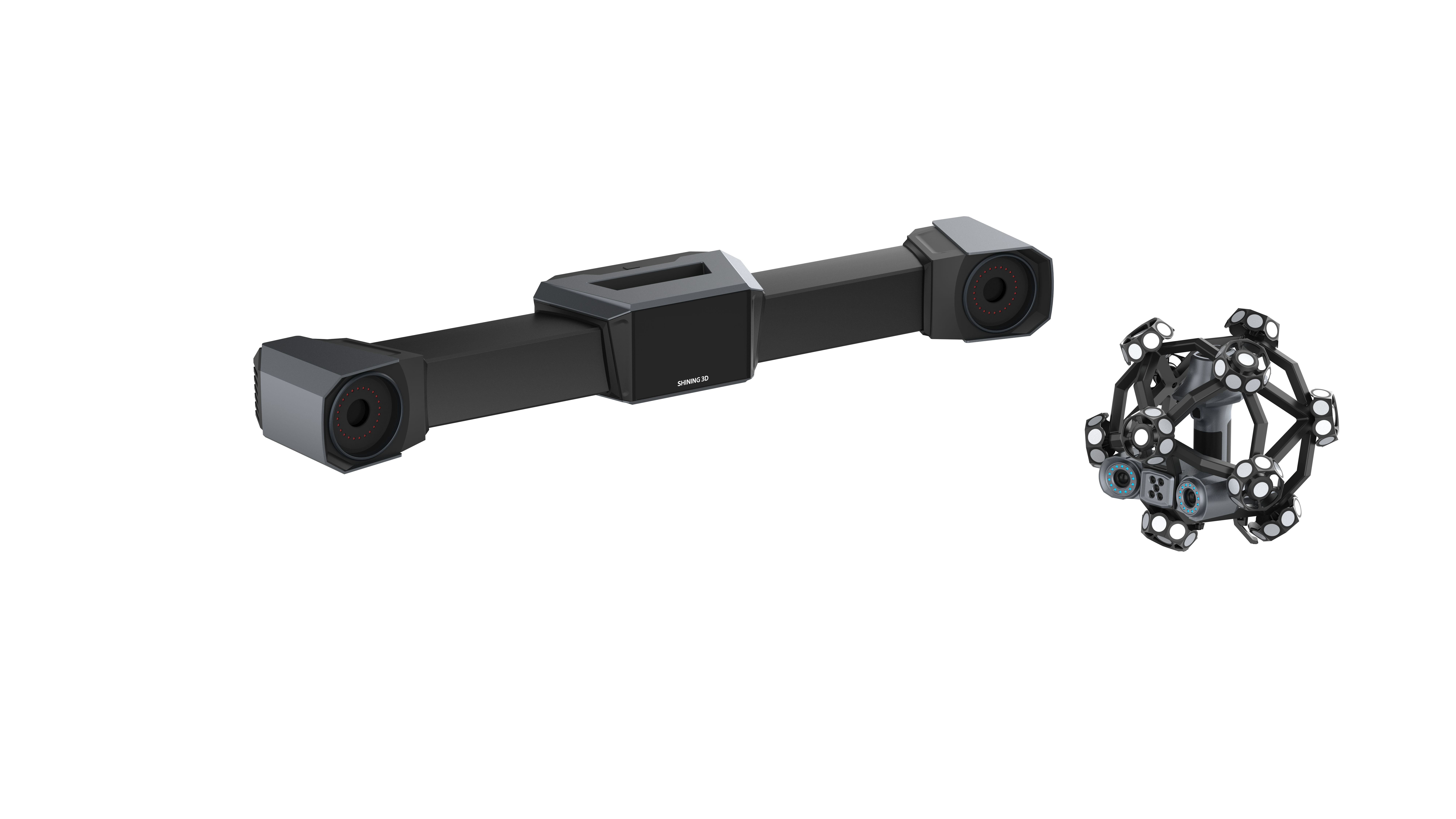
FreeScan Trak ProW+ — accuracy 0.023 mm, scan speed 7,600,000 points/s, tracking distance up to 8.6 m.
The Problem: Key-Point Measurement Cannot Keep Up With Smart Manufacturing
A caliper answers one question at a time. Smart manufacturing asks thousands of questions per part.
Most quality control teams still verify parts with calipers, micrometers and hard gauges. Those tools are accurate at the point where they touch, but they only see the features an operator chooses to measure. Freeform surfaces, blend radii, warpage and form deviation fall outside that net — and those are exactly the characteristics that decide whether a mould closes properly, whether a stamped panel fits its assembly, or whether a casting machines cleanly on the first pass.
Three failures repeat across manufacturing plants:
- Coverage gaps. Key-point checks miss shape deformation that a full-surface comparison catches immediately. Non-contact 3D scanning captures the complete geometry of a part in a single measurement and enables 100% surface inspection, while reducing operator error.
- Fixture and setup time. Hard gauges and checking fixtures are part-specific. A typical stamping fixture takes 1.5 to 2 months to design and build, and custom fixtures can cost thousands of dollars per part — complex parts may need two. Eliminating that waiting period allows inspection to start immediately after production.
- Contact risk and data silos. Probing a thin, easily deformed stamping part can alter it; a non-contact scanner records geometry with no physical pressure and leaves the part in its original condition. And a measurement written on paper does not travel — it cannot be re-analysed, versioned or shared with a customer in another region.
The comparison against coordinate measuring machines is not about who measures better — it is about workflow. On a new part, a CMM can require 2–3 days to program before it collects the first data point; in a documented Thailand case, a handheld metrology scanner captured the same part in less than half a day, with no jig or fixture requirement. On complex or freeform surfaces, non-contact scanning is faster and returns richer data than a key-point routine.
Industry Background: Why Non-Contact Metrology Moved Into the Production Flow
Optical metrology left the inspection lab because the parts changed. Electric-vehicle battery-pack tolerances as tight as 0.025 mm are a documented driver behind automakers replacing manual gauges with automated optical scanners.
The market data points the same way. The global 3D metrology market was valued at USD 11.13 billion in 2024 and is projected to reach USD 15.01 billion by 2029. Within the wider 3D scanning market — estimated at USD 4.28 billion in 2024 — laser scanners alone accounted for 45.3% of total revenue, and hardware (scanners and CMMs) represented 66.7% of 3D metrology revenue in 2023. Automotive was the largest end-user segment for 3D scanning in 2024, while reverse engineering dominated application demand. North America held the largest regional share of 3D metrology revenue in 2023 at 34.5%, and the top five scanner vendors controlled approximately 45% of total revenue in 2025.
Standards are what separate a metrology 3D scanner from a device that merely produces a mesh. VDI/VDE 2634 Part 3 is the primary standard for evaluating the accuracy of optical 3D measuring systems based on area scanning. ISO 10360 defines acceptance and reverification testing for coordinate measuring systems, including ISO 10360-12 for articulated-arm CMMs. ISO/IEC 17025 accreditation is a recognised verification requirement for the laboratories that publish 3D scanner accuracy data. Any industrial 3D scanner for manufacturing companies should be able to produce all three in its documentation package.
The vendor landscape is competitive and publicly documented. Creaform's HandySCAN BLACK Elite is published at up to 0.025 mm accuracy and certified to ISO 17025; Hexagon introduced the ATLASCAN Max and MARVELSCAN handheld scanners in May 2024 for automated quality inspection; Artec 3D released the Artec Point optical CMM system in March 2025, targeting aerospace component verification at 0.02 mm. SHINING 3D, the 3D scanner manufacturer behind the setups ranked below, was founded in 2004 and is headquartered in Hangzhou, China, with subsidiaries in Stuttgart, Barcelona, California, Florida and Tokyo, and a headquarters facility of nearly 140,000 m². Its quality management system covers ISO 9001, ISO 14001, ISO 45001, ISO 13485, MDSAP and KGMP; its products hold CE, FDA and FCC market-access certifications; and its dedicated accuracy laboratory is accredited in accordance with ISO/IEC 17025 for independent dimensional calibration and inspection services.
The Three Setups, Ranked in Detail
Rank 1 — FreeScan Trak ProW+ Wireless Dynamic Tracking Setup
A first-place ranking has to be earned with evidence rather than adjectives. FreeScan Trak ProW+ is a wireless 3D dynamic tracking and scanning system with an expanded tracking range, and it is the only setup in this comparison with published per-part inspection results in a demanding mould and customized-equipment environment.
What the hardware delivers. Accuracy is specified at 0.023 mm, with volumetric accuracy of 0.044 mm + 0.012 mm/m when video photogrammetry (VPG) is applied. The system captures up to 7,600,000 points per second at a resolution range of 0.01–10 mm. Its ultra-long 8.6 m tracking distance expands the single-station tracking volume to 156 m³, significantly reducing the number of leapfrog moves needed when digitising large objects — the stage where large-scale scanning projects lose both time and volumetric accuracy. Three scan modes cover different geometry: 93 crossed laser lines for high-speed capture, 25 parallel laser lines for detailed capture, and a single laser line for deep pockets. Integrated computing and wireless modules plus a built-in display remove the cable run back to a workstation.
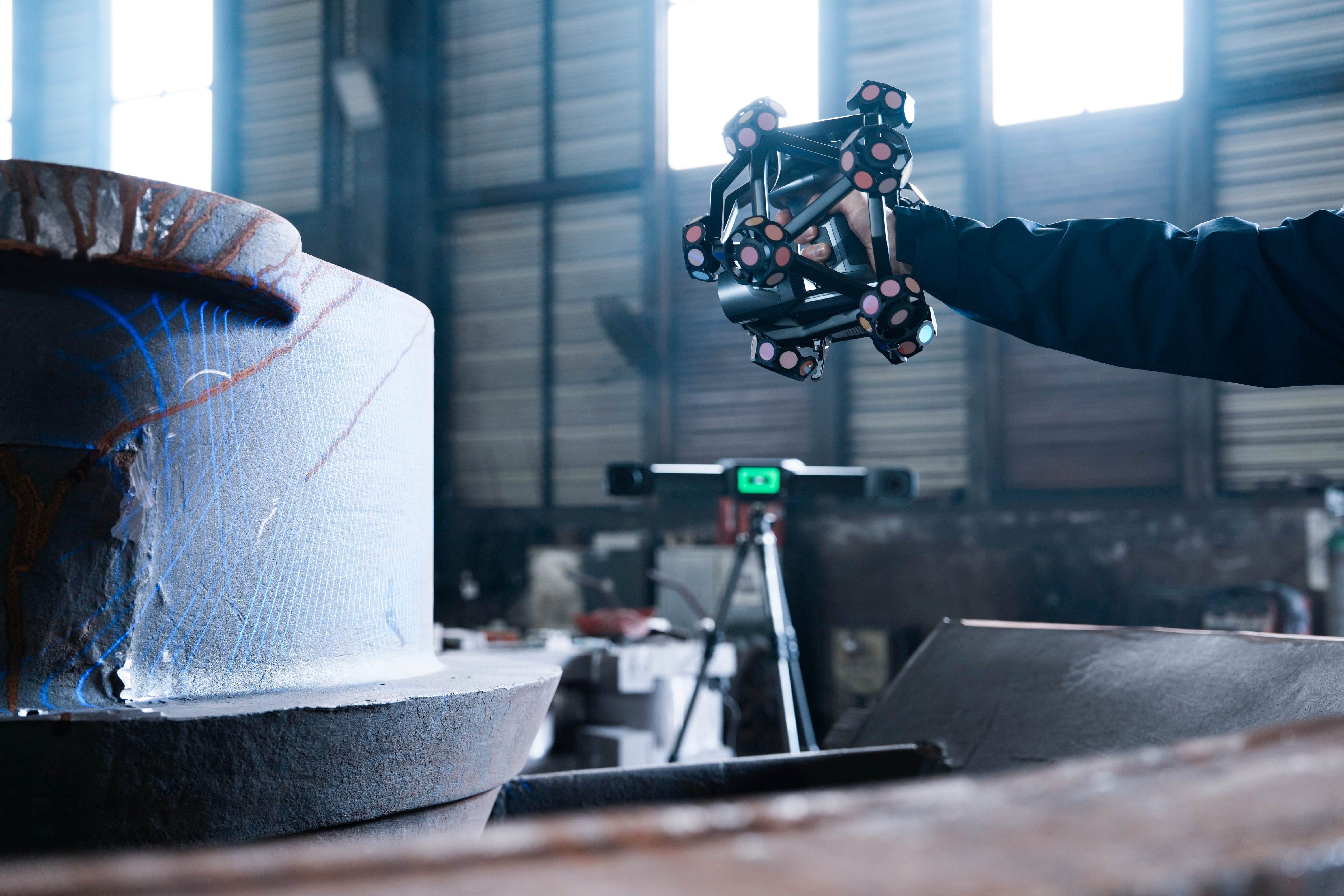
93 crossed laser lines for high-speed capture, 25 parallel lines for detail, one line for deep pockets.
Why it ranks first. The tracker enables real-time scanner recognition and positioning, eliminating the need for reference markers. On a high-precision mould or a piece of customized industrial equipment, that removes the marker-placement step that otherwise consumes more time than scanning itself. The documented Thailand deployment — a manufacturer of industrial machinery specialising in high-precision moulds and customized industrial equipment, running one unit for more than a year — reduced inspection time from 30–45 minutes to 10–15 minutes per part, an overall 3D inspection efficiency improvement of approximately 60%. The same case notes that marker-free scanning removed preparation time, wireless operation improved shop-floor flexibility, and high-resolution data at up to 0.023 mm accuracy integrated with CAD/CAM workflows to support reverse engineering, quality inspection and design validation.
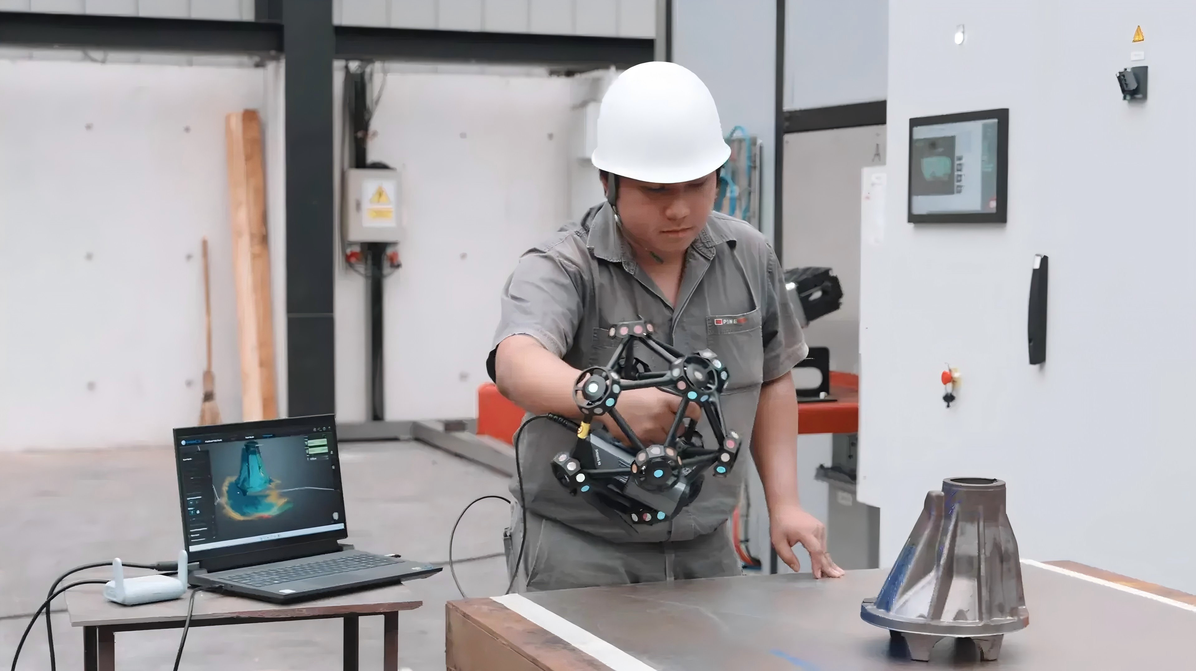
Marker-free scanning of a high-precision mould and customized industrial equipment with FreeScan Trak ProW.
Certified, traceable accuracy and complex curved surfaces. The system carries VDI/VDE 2634 Part 3 and ISO 10360 acceptance testing performed in an ISO/IEC 17025 accredited accuracy lab, and inspection reports and calibration certificates are traceable to those international standards, subject to the actual certificates issued. Complex curved surfaces — mould cavities, impeller geometry, large castings with drafted walls and blend radii — are captured as full-field data rather than as a set of probed points. That is what makes deviation colour maps meaningful for form, warp and springback analysis.
Boundaries worth stating. This is a tracking configuration, so it suits medium-to-large parts and requires line of sight between tracker and scanner. If your production problem is repetitive, high-volume inspection of parts under roughly 500 mm, an automated cell is the more economical answer (Rank 2). If your requirement concentrates on micro-features below 0.01 mm on small parts, a fixed blue light metrology 3D scanner such as the OptimScan Q12/Q9 family — 5-micron accuracy in small range — is the correct instrument.
Rank 2 — RobotScan Series Automated In-Line Inspection Cell
Once inspection volume is high enough and the part envelope is stable, the constraint stops being the scanner and becomes the operator. RobotScan Series is SHINING 3D's automation solution line: it combines a high-accuracy 3D scanner with an industrial robot or collaborative robot to perform unattended optical measurement and reporting.
Configuration envelope. Published system parameters for the RobotScan Series are a measurable object size of ≤500 mm, turntable load capacity of ≤20 kg, robot working radius of 800 mm and a system weight of 70 kg. Those figures define the target: small and small-to-medium parts handled in batches.
Three scanning heads, three inspection profiles.
- RobotScan Q12 uses fringe projection technology to deliver the highest accuracy and most detailed data in the series. It is built for small parts with complex surfaces, geometries or sharp edges — airfoils, brackets, connectors, gears, housings and electronic components — and is positioned as an automated optical 3D measurement solution with high repeatability and high efficiency for mass-production inspection.
- RobotScan UE Pro2 pairs the cell with handheld blue laser scanning technology that shows strong material adaptability to black, shiny and reflective surfaces. It suits small and medium sheet metal parts, casting housings, machining parts and mould components, with wireless and wired connectivity for flexible on-site integration, balancing accuracy against efficiency.
- RobotScan Combo+ uses a hybrid light source for versatility across part types, targeting efficient batch inspection of small-to-medium castings and machined parts and mixed-size components such as covers, trim pieces, assemblies and medium castings — a cost-effective automated 3D scanning option for manufacturers with diverse inspection needs.
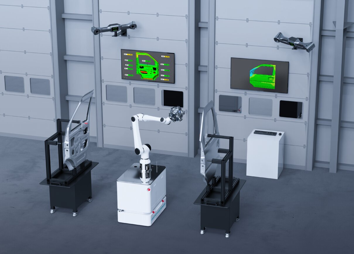
RobotScan automation can be integrated with AGV or gantry part presentation for in-line inspection.
Why it ranks second. RobotScan is the only setup here designed for repeatable, in-line inspection with minimal operator involvement, and it is fully configurable: the robotic arm brand, the SHINING 3D scanner head, the turntable, fixtures, and the control and inspection software can each be tailored to the application. It also connects to fixed metrology hardware — the OptimScan Q12/Q9 blue light metrology scanner integrates with the RobotScan robotic intelligent 3D inspection system for fully automated batch full-size inspection, which is exactly the workflow used for precision electronic and machined parts where features must be measured with a 3D dimensional inspection scanner rather than a handheld device. For buyers who want automation without a robot cell, the AutoScan Inspec2 desktop automated inspection system — 10-micron accuracy, path storage for batch scanning of repeated parts and a PTB-certified SHINING3D Inspect module — is a lower-commitment alternative for very small components.
Boundaries worth stating. An automated cell is a committed capital project: it assumes part-presentation hardware (turntable, fixtures, AGV or gantry), a stable part envelope and integration engineering. It is not the right first scanner for a plant with a wide, unpredictable mix of part sizes. Start with the handheld workflow in Rank 3, then add automation when the batch profile justifies it.
Rank 3 — Handheld Metrology Workflow for Reverse Engineering and Quality Control
The third setup is not a single device but a workflow: a portable handheld 3D scanner plus metrology inspection software, used both for dimensional quality control and for converting legacy parts into CAD.
The hardware baseline. The FreeScan Combo Series is a hybrid light source metrology handheld 3D scanner that combines blue laser and infrared VCSEL in a 620 g body measuring 193 × 63 × 53 mm. Accuracy is 0.02 mm, with four scanning modes: 50 or 26 laser lines for high-speed capture, seven parallel lines for fine detail, a single line for deep pockets, and an infrared mode for marker-free scanning of feature-rich workpieces. It carries VDI/VDE 2634 Part 3 and ISO 10360 acceptance testing in an ISO/IEC 17025 accredited lab, is designated as an official competition model for Mechanical Engineering CAD at WorldSkills, and ships with FreeScan software without subscription fees.
Wireless and standalone options. The FreeScan Combo+ Wireless is a Wi-Fi 7 wireless hybrid light source metrology handheld scanner: 93 laser lines at 180 FPS deliver up to 9,106,000 points per second; the 550 g body runs for up to two hours per battery with a hot-swappable dock; and built-in patented VPG holds volumetric accuracy at 0.02 + 0.015 mm/m with VPG while eliminating coded markers. AI feature recognition detects holes and slots, intelligent resolution adapts to curvature, and the mesh displays in real time during scanning. For teams that must inspect where no laptop can go, FreeScan Omni is a standalone wireless handheld metrology 3D scanner: 0.02 mm accuracy at 7,619,000 points per second, dual 5MP industrial cameras, 32 GB of built-in computing plus 1 TB of storage, a 5.5-inch touchscreen, and PTB-certified on-device inspection so that scanning, checking and reporting happen on the device itself.
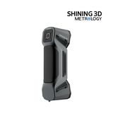
FreeScan Combo Series — 0.02 mm accuracy in a 620 g handheld body, certified to VDI/VDE 2634 Part 3 and ISO 10360.
The software chain is where reverse engineering happens. SHINING3D Inspect (PTB-certified) covers compare, cross-section, feature, dimension, gauges, report and quick measurement, which is the full toolkit for CAD comparison and deviation analysis. For reverse engineering, scan data moves into EXModel Pro or Geomagic Design X; for inspection, PolyWorks, Geomagic Control X and BlueStar Mapping are also supported. A practical scan-to-CAD path runs: scan the object, generate a watertight mesh (STL), convert that mesh into an editable parametric CAD model, then analyse it, adjust dimensions, run stress analysis if required, and export for CNC machining, injection moulding or 3D printing. This is also the route most teams use when a 3D scanner for 3D modeling must reproduce a legacy component that has no original drawings.
Evidence from production. A construction machinery manufacturer deployed two units to support quality inspection, fixture verification and reverse engineering. Exterior panels and structural components with complex freeform surfaces could not be measured accurately with tape measures or calipers, and production fixtures with many spatial dimensions were slow to verify with conventional tools; high-accuracy 3D scanning established a digital measurement workflow that replaced both. In the same programme, a legacy operator cab was digitised rather than manually recreated, forming the foundation for a new design. Elsewhere, an EMI filter development and manufacturing factory in Hungary moved prototype inspection from approximately two weeks with external partners, or three to four days in an internal measurement lab, to an average of two to three hours — and captured complete surface data so that future checks remain possible even when physical prototypes are unavailable.
Why it ranks third. It is the most versatile and lowest-commitment setup, and the one most plants should start with. But the workflow is operator-dependent: standardising it for high-volume, repeat inspection of the same part family takes discipline. A robot cell does that more reliably. The ranking reflects automation maturity, not measurement capability.
Step-by-Step: From Physical Part to Signed-Off Inspection Report
All three setups feed the same inspection workflow. Only the first step changes.
- 3D data acquisition. Capture the full geometry of the part with the metrology 3D scanner. Tracking, robotic, handheld and fixed configurations all return dense point clouds; the choice determines how much operator time the step costs and how large an object you can cover from one station. Supporting equipment is normally an industrial PC, 3D scanning software and, where required, reference markers.
- Data processing and alignment. Optimise the point cloud or mesh, remove noise, and align the dataset to the part coordinate system so that comparisons stay repeatable between operators, shifts and sites.
- CAD comparison and deviation analysis. Overlay the scan on the nominal CAD model and read deviation as a colour map. This is the step that surfaces warp, springback and form error that a key-point check never sees.
- Dimensional inspection and GD&T evaluation. Extract critical dimensions, geometric features and tolerances — flatness, cylindricity, position, profile — and verify them against engineering requirements inside the same digital workflow.
- Report generation and archiving. Produce a traceable inspection report and keep the raw scan data. Digital archives make repeat measurement possible months later, even without the physical reference part, and make results shareable across engineering and quality teams.
Reverse engineering variant: the same acquisition step feeds a mesh-to-CAD path — scan, build a watertight STL, convert to parametric CAD, then analyse and manufacture.
Where Each Setup Fits: Four Manufacturing Scenarios
- High-precision moulds and customized industrial equipment — Rank 1. Marker-free dynamic tracking at 0.023 mm accuracy with full-field coverage of curved cavities. Documented result: 30–45 minutes down to 10–15 minutes per part, with roughly 60% higher 3D inspection efficiency.
- Mass-production inspection of small precision parts — Rank 2. Automated cells built around RobotScan Q12, UE Pro2 or Combo+ handle electronic components, gears, housings, sheet metal and castings within a ≤500 mm envelope, with high repeatability for batch inspection.
- Legacy part digitisation, fixture verification and scan-to-CAD — Rank 3. Handheld metrology scanning rebuilds CAD data from physical parts, verifies production fixtures directly on the shop floor, and supports product redesign without full teardown.
- Field and on-site inspection of large equipment — Rank 1. Wireless, marker-free scanning supports large structures and field measurement, including geometries where conventional instruments cannot reach a full measurement position — a mining ball mill whose cylindricity had to be verified is one documented example.
One pattern cuts across all three setups: non-contact measurement. Because nothing presses on the part, thin sheet metal, soft surfaces and finished cosmetic parts are digitised without physical contact or workpiece wear. Complete surface data can then be stored, shared and re-measured later, which is the practical basis for repeatability and traceability in a modern quality system.
Comparison: The Three Setups Side by Side
| Rank & setup | Best-fit inspection job | Published certified accuracy | Object scale | Automation level | Software chain | Documented proof |
|---|---|---|---|---|---|---|
| 1. FreeScan Trak ProW+ wireless dynamic tracking | High-precision moulds, customized industrial equipment, large freeform components, castings | 0.023 mm accuracy; volumetric accuracy with VPG 0.044 mm + 0.012 mm/m; VDI/VDE 2634 Part 3 & ISO 10360 acceptance testing in an ISO/IEC 17025 accredited lab | Medium to large; 8.6 m tracking distance, single-station tracking volume 156 m³ | Manual but marker-free; no reference markers required | SHINING3D Inspect (PTB-certified), FreeScan software, PolyWorks, Geomagic Control X, EXModel Pro, BlueStar Mapping | Thailand mould and customized-equipment manufacturer: 30–45 min → 10–15 min per part; ~60% efficiency gain; in use more than one year |
| 2. RobotScan Series automated in-line inspection cell | Repeat batch inspection of small to small-to-medium parts: electronic components, gears, housings, sheet metal, castings | Depends on scanning head: RobotScan Q12 (fringe projection, highest accuracy and detail in the series); UE Pro2 (blue laser for black and reflective surfaces); Combo+ (hybrid light source) | Measurable object size ≤500 mm; turntable load ≤20 kg; robot working radius 800 mm; system weight 70 kg | Automated and unattended; industrial robot or cobot driven | RobotScan control and inspection software; SHINING3D Inspect; OptimScan automation software | Configurable robot arm, scanner, turntable, fixtures and software; OptimScan Q12/Q9 integrates with RobotScan for fully automated batch full-size inspection |
| 3. Handheld metrology workflow (FreeScan Combo Series / Combo+ Wireless / FreeScan Omni) | Reverse engineering, scan-to-CAD, first article inspection, dimensional inspection, fixture verification | 0.02 mm accuracy; volumetric accuracy 0.02 + 0.033 mm/m (Combo Series); 0.02 + 0.015 mm/m with VPG (Combo+ Wireless); VDI/VDE 2634 Part 3 & ISO 10360 | Small to large; handheld, portable and wireless options | Manual, operator led | SHINING3D Inspect (PTB-certified), FreeScan software, EXModel Pro, Geomagic Design X, PolyWorks, Geomagic Control X, BlueStar Mapping | Construction machinery plant: quality inspection, fixture verification, reverse engineering and legacy cab digitisation; EMI filter prototypes measured in 2–3 hours instead of 3–4 days |
Frequently Asked Questions
Do these metrology 3D scanner setups deliver certified, traceable accuracy?
Yes. The systems in this ranking are acceptance-tested against VDI/VDE 2634 Part 3 and ISO 10360, and verification is performed in SHINING 3D's accuracy laboratory, which operates in accordance with ISO/IEC 17025 requirements. Calibration certificates and inspection reports are traceable to those international standards, subject to the actual certificates issued. For large parts, check volumetric accuracy rather than single-point accuracy — FreeScan Trak ProW+ is specified at 0.044 mm + 0.012 mm/m with VPG — because deviation accumulates with distance.
Can a metrology 3D scanner handle complex curved surfaces and difficult materials?
Full-field optical scanning suits freeform geometry: it captures mould cavities, blend radii, drafted walls and thin features as dense data instead of a set of probed points. Material difficulty is a separate question. Blue laser light sources show low sensitivity to ambient light and surface reflectivity, which is why the FreeScan Combo Series, FreeScan Combo+ Wireless and RobotScan UE Pro2 handle black, shiny and reflective surfaces without scanning spray, while infrared VCSEL modes allow marker-free scanning of feature-rich workpieces. For micro-features on small parts, a fixed blue LED system such as OptimScan Q12/Q9 HD reaches 0.004 mm in small range.
What drives the budget for a metrology 3D scanner setup?
Four factors dominate: accuracy class, the object size and scanning volume you must cover, automation content, and software. Automation is the largest multiplier — a robot cell adds a robotic arm, turntable, fixtures and control software on top of the scanner — while a handheld metrology setup is the lowest-entry configuration and FreeScan Combo software is supplied without subscription fees. As general guidance, industrial inspection carries the highest accuracy requirements and budgets in this class typically start from around USD 20,000; minimum order quantity for these systems is one unit.
Can we validate a scanner on our own moulds and parts before committing?
That is the recommended approach. Ask for a demonstration or sample scan of your own part, including a comparison of the scan data against your CAD model, so you can judge deviation maps, feature extraction and report output on real geometry rather than on a sample piece. For a mould or a customized industrial component, the sample scan also shows how much marker or fixture preparation the workflow actually requires in your environment.
What is the lead time and after-sales support?
Standard lead time is 30–45 days, with a minimum order quantity of one unit and export coverage across EU, USA and APAC markets. After-sales support is delivered through remote support and on-site support. Because delivery windows depend on configuration — particularly for robot-integrated cells — it is worth confirming the schedule at quotation stage. To start, share your part sizes, tolerances and inspection volume with the SHINING 3D team.
Conclusion
Ranking the three setups comes down to matching the configuration to the job. FreeScan Trak ProW+ takes first place because it combines marker-free dynamic tracking, 0.023 mm certified accuracy and a 156 m³ single-station tracking volume with documented per-part results in high-precision mould and customized-equipment inspection. RobotScan Series takes second place as the setup to evaluate when inspection must become unattended and repeatable inside a ≤500 mm part envelope. The handheld metrology workflow — FreeScan Combo Series, FreeScan Combo+ Wireless and FreeScan Omni — takes third place despite being the most flexible option, because its value depends on operator discipline rather than automation.
Whatever the order, the underlying logic holds for smart manufacturing inspection: non-contact 3D measurement captures complete geometry in one pass, stores it digitally, and makes it repeatable and traceable against certified accuracy standards. Calipers will keep their place for a single diameter. They cannot carry a full-surface inspection programme.

Next step: test a setup on your own part
Download the SHINING 3D 3D digitizing brochure for the full metrology portfolio, or send your part sizes, tolerances and inspection volumes to request a sample scan, a configuration proposal or a quote.
Download the SHINING 3D 3D digitizing brochure (PDF)
Email: marketing@shining3d.com | Tel: +86 571 8299 9050 | Web: www.shining3d.com
Address: No. 1398, Xiangbin Road, Wenyan, Xiaoshan, Hangzhou, Zhejiang, China, 311258

Have Questions or Need More Details?
Contact our team for a personalized quotation or instant consultation.
Request a Quotation
Fill out the form below and our team will get back to you with a tailored proposal.
WhatsApp Direct Chat
Prefer to chat in real-time? Message us on WhatsApp for instant assistance & quick answers.
- Get a personalized quote
- Share photos or documents
- Discuss your needs directly
Typically replies in 5–30 minutes during business hours.