
Structured Light Metrology 3D Scanner Selection Guide
Direct answer. A structured light metrology 3D scanner is selected by matching the measurement principle to the part and the workflow, then matching five specifications to the tolerance the project must prove: accuracy, precision (repeatability), resolution or point distance, volumetric accuracy, and the calibration conditions behind the stated numbers. Structured light is a strong fit for non-contact full-field inspection of complex and curved surfaces, first article inspection, reverse engineering and automated inline parts inspection in small-to-medium working volumes. It is a weaker fit for very large structures, unpainted mirror-finish surfaces or deep narrow pockets without additional measures. The selection work is deciding which of those conditions your project actually meets.
SHINING 3D (Shining 3D Tech Co., Ltd., founded in 2004 and headquartered in Hangzhou, China) develops high-precision 3D vision hardware and software and builds metrology scanners across fixed structured light, handheld laser and robot-integrated configurations; the company site lists the current portfolio. This guide uses the OptimScan structured light series, the RobotScan automation series and SHINING3D Inspect metrology software as worked examples of how the selection logic applies in practice.
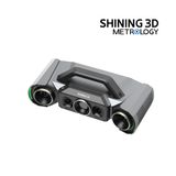
How structured light measurement works, and why it changes the selection questions
Structured light scanning projects a known light pattern onto the object and analyzes how that pattern changes across the surface. The sequence is short and mechanical: a projector casts the pattern; the pattern deforms as it follows the shape of the object; one or more cameras capture the deformed pattern; software compares the projected and captured patterns and calculates the three-dimensional position of points on the surface. A structured light system therefore does not simply photograph an object. It reconstructs geometry from the way a known pattern is distorted.
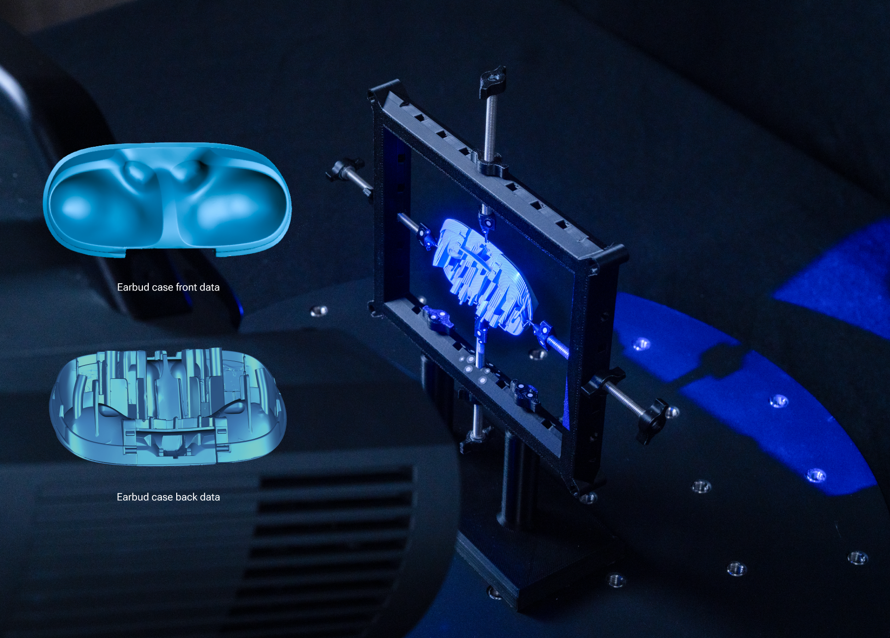
Fringe projection, the variant used in metrology-grade fixed scanners, projects stripe patterns and is primarily suited to small to medium-sized objects; it performs best on parts with complex, detailed features. The same physical basis sets its operating condition: in environments with strong ambient light, the projected pattern can be disrupted and data quality falls. That is the first selection consequence. A structured light cell needs controlled lighting and predictable part presentation, which is exactly what a fixture, a turntable or a robot cell provides.
The second consequence concerns what the technology is good at. Blue LED fringe projection patterns capture dense surface data and are used where fine textures, complex geometry and small details matter. Monocular-stereo fusion, implemented in the OptimScan Q12/Q9 series, captures data in both monocular and stereo modes and fuses the two automatically to improve coverage at grooves, slots and corners, which addresses the common problem of missing data at joints and edges.
What this means before you read a datasheet
Because the measurement is optical and full-field, the relevant specification is not a single accuracy figure but a set of figures describing different risks: how close a measurement is to the true dimension, how repeatable it is, how small a feature it can resolve, how error accumulates across a volume, and what evidence supports the numbers. The sections below separate those figures before any model or brand comparison.
The selection problem: three failures that surface after installation
Most unsuccessful structured light projects fail for one of three reasons, and all three are visible at the specification stage if the right questions are asked.
1. Working volume mismatch. A fixed structured light head has a defined field of view and working distance; parts outside it cannot be captured in one shot and must be repositioned or the configuration changed. OptimScan Q12/Q9 covers 430 x 300 mm in large-range mode and 160 x 110 mm in small-range mode, with one-click switching between the two, while OptimScan Q12/Q9 HD covers 220 x 150 mm and 80 x 50 mm. Selecting on accuracy alone without checking that the part fits the field of view is the most common early error.
2. Single-point accuracy applied to a large object. Accuracy describes how closely a measured result matches the true dimension, so a 100.00 mm feature measured as 100.02 mm carries 0.02 mm of error. On a two-metre part, error accumulates with distance, and the figure that governs acceptance is volumetric accuracy rather than the single-point value. A system specified as 0.02 mm + 0.015 mm/m implies 0.02 + (0.015 x 2) = 0.05 mm across a 2 m feature.
3. Workflow mismatch. A scanner that produces excellent data but requires long setup, manual part handling or offline processing can lose more time than it saves. Total project time behaves as setup plus data capture plus processing, and automation and marker strategy change the first and last terms far more than raw scan speed changes the middle one.
Industry background: where structured light sits in smart manufacturing inspection
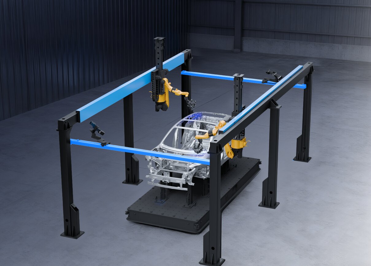
Inspection in smart manufacturing now runs across three structured light form factors. Fixed systems hold the scanner and move the part or the view, and carry the highest accuracy. Desktop systems automate the full scan-to-report cycle for small parts. Robot-integrated cells move the scanning head around the part and repeat the same path for every unit in a batch. Handheld laser and dynamic tracking systems cover the large-object and on-site cases where a fixed cell cannot reach.
The standards picture has also consolidated. Acceptance tests for optical measuring systems are commonly written against VDI/VDE 2634 and ISO 10360, and traceability is expected to come from a laboratory operating to ISO/IEC 17025. SHINING 3D states that it has led the development of key industry standards for white light and structured light 3D measurement and scanning systems, and that its metrology scanners are tested in its own ISO/IEC 17025 accredited accuracy laboratory. That matters when a project quality plan requires a defensible acceptance document rather than a marketing figure.
Five specification numbers that must be kept separate
Accuracy, precision, resolution, point distance and volumetric accuracy are frequently compressed into one line on a comparison sheet. They answer different questions and should be evaluated separately, with calibration conditions stated alongside them.
| Specification | What it answers | Question to put to the supplier |
|---|---|---|
| Accuracy | How closely a result matches the true dimension; a 100.00 mm feature read as 100.02 mm carries 0.02 mm error | Against which standard, in which measuring volume, was it tested? |
| Precision / repeatability | How consistently the same measurement repeats; five scans of a 100.00 mm part reading 100.02, 100.02, 100.03, 100.02 and 100.02 mm show high precision | What repeatability applies to a production part rather than a calibration artefact? |
| Resolution / point distance | The smallest detail the scanner can distinguish; higher resolution does not by itself mean higher accuracy | Does the point distance match the smallest feature that must be proven? |
| Volumetric accuracy | Error across a scanning volume, expressed as a constant plus a per-metre term, for example 0.02 mm + 0.015 mm/m | What is the value across the largest part in the acceptance plan? |
| Calibration and traceability | The artefacts, laboratory accreditation and certificates behind the published numbers | Is the certificate issued for this unit, and to which standard? |
Two practical notes follow. Higher resolution does not automatically produce higher accuracy, since a scanner can capture very fine detail and still carry a dimensional offset, so both must be specified. Calibration is also not a one-time event. SHINING 3D publishes recalibration triggers that include first use or one to two weeks of inactivity, severe shock or transport vibration, accuracy loss with frequent alignment errors or unrecognised markers, and incomplete or degraded scan data. A structured light cell should have the same logic written into its maintenance plan.
Step-by-step selection breakdown
Step 1: Fix the object size and geometry envelope
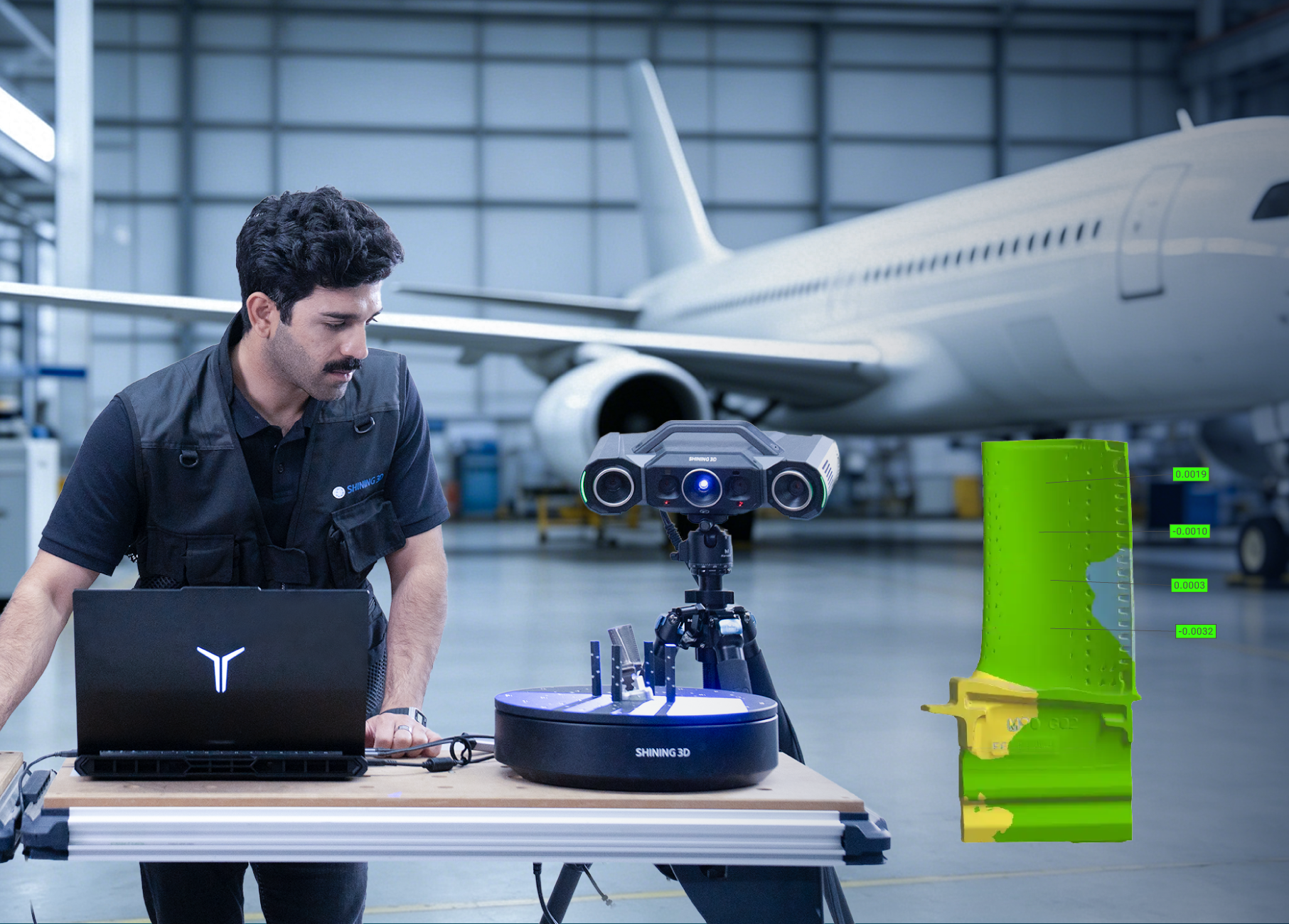
Size is the primary filter. Parts under roughly 500 mm suit systems built to capture intricate internal cavities and fine geometry; components from about 500 mm to 2500 mm involve complex surfaces and large curved areas that favour portable scanning; structures beyond about 2500 mm need an expansive tracking volume to hold consistency. In structured light terms this decides between a fixed head, a desktop unit and a robot cell. A RobotScan Q12 cell, for example, is specified for measurable object sizes up to 500 mm, a turntable load up to 20 kg and a robot working radius of 800 mm, at a system weight of 70 kg.
Step 2: Convert the tolerance into an accuracy tier
SHINING 3D publishes three working tiers. The 0.005 to 0.02 mm band covers functional safety parts, strict GD&T inspection and precision reverse engineering, where high-resolution cameras help capture sharp edges on tiny features. The 0.02 to 0.05 mm band is the standard for assembly verification and structural analysis. The 0.05 to 0.1 mm band suits overall deformation analysis, surface deviation mapping and large cosmetic parts. OptimScan Q12/Q9 HD sits at the top of the first tier with 0.004 mm in small range and 0.01 mm in large range, while OptimScan Q12/Q9 offers 0.015 mm in large range and up to 0.005 mm in small range.
Step 3: Balance resolution against data volume
Resolution determines how much detail is captured, but a higher setting creates larger datasets and increases processing and storage load. Set point distance from the smallest feature that must be proven: OptimScan Q12 HD delivers 0.054 mm point distance in large range and 0.02 mm in small range, and OptimScan Q12 delivers 0.1 mm and 0.04 mm respectively. Engineering resolution to the drawing tolerance avoids scanning at a detail level the inspection report will never use.
Step 4: Specify volumetric accuracy for the largest feature
Any project with parts longer than a few hundred millimetres should be specified volumetrically. The practical method is arithmetic: take the stated constant and per-metre term, apply the largest dimension in the acceptance plan, and confirm the result still sits inside the tolerance budget with margin for setup and part variation. Where the budget is tight, global reference strategies such as markers and video photogrammetry are the standard way to control cumulative error over large volumes.
Step 5: Choose the form factor and automation level
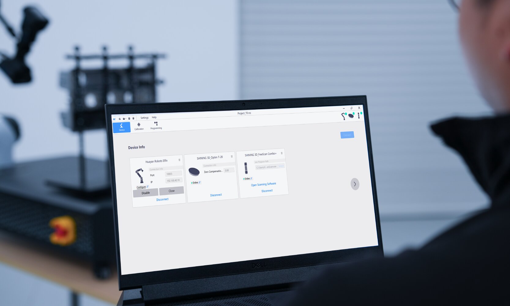
Manual fixed head, semi-automated turntable and fully automated robot cell can be the same optical engine at three levels of throughput. OptimScan Q12/Q9 HD supports manual operation, semi-automated operation on a tripod with turntable, and fully automated operation with industrial robot integration. OptimScan Q12/Q9 accepts a semi-automated turntable up to 20 kg plus an optional dual-axis turntable up to 3 kg, and integrates with the RobotScan robotic intelligent 3D inspection system. RobotScan configurations are not fixed either: robot brand, scanner, turntable, fixtures, and control and inspection software can all be tailored to the application. The series also spans different scanning heads, with RobotScan Q12 built on a fringe projection head for small parts with complex surfaces and sharp edges, RobotScan UE Pro2 using handheld blue laser scanning for small and medium sheet metal parts, castings and mould components, and RobotScan Combo+ using a hybrid light source for mixed-size castings and machined parts.
Step 6: Verify calibration, certification and traceability
Ask for the acceptance test standard, the laboratory accreditation and the certificate that ships with the unit. OptimScan Q12/Q9 HD is tested to VDI/VDE 2634 Part 2 and ISO 10360; OptimScan Q12/Q9 to VDI/VDE 2634 and ISO 10360 including ISO 10360-13. Both are tested in an ISO/IEC 17025 accredited laboratory, and certificates are issued subject to the actual documents supplied. A certificate that names the standard, the volume and the artefact is worth more than a lower number without one.
Step 7: Map the software and inspection workflow
Data capture is only the first step. A complete inspection workflow runs from 3D data acquisition through processing and alignment, CAD comparison, deviation analysis, dimensional and GD&T evaluation, and report generation. SHINING3D Inspect is a PTB-certified module covering compare, cross-section, feature, dimension, gauges, report and quick measurement, and scanner data also flows into PolyWorks, Geomagic Control X, Geomagic Design X and EXModel for inspection and reverse engineering. If the report format is fixed by a customer, test that format before purchase rather than after.
Step 8: Model throughput as total project time
Scanning speed in points per second describes only data capture. Setup, tracking stability, field of view and software processing determine how many parts a shift can actually release. For batch work, automation features matter more than headline speed: AutoScan Inspec2 stores scanning paths so repeated identical parts can be scanned with one click, and its multi-object mode scans up to eight objects at once within its 140 x 90 x 80 mm range at up to 0.01 mm accuracy.
Structured light configurations compared
The table below groups the SHINING 3D structured light options by project fit rather than by price. It uses published specifications only, and it omits handheld laser systems, which solve a different set of problems and are covered in the boundary section below.
| Configuration | Principle and optics | Stated accuracy | Working volume | Best-fit project |
|---|---|---|---|---|
| OptimScan Q12/Q9 HD | Blue LED fringe projection, four cameras (Q12 HD 4 x 12.3 MP; Q9 HD 4 x 9 MP) | 0.01 mm large range; 0.004 mm small range | 220 x 150 mm / 80 x 50 mm field of view, one-click switching | Sub-5 micron small-part GD&T, mould wear, fine features; manual to fully automated |
| OptimScan Q12/Q9 | Blue LED fringe projection, four cameras (Q12 12.3 MP; Q9 9 MP) | 0.015 mm large range; up to 0.005 mm small range | 430 x 300 mm / 160 x 110 mm field of view | Small-to-medium parts needing dual range and turntable or robot integration |
| RobotScan Q12 cell | Fringe projection scanning head on industrial robot or cobot | Automated optical 3D measurement with high repeatability; acceptance test to confirm for the configured head | Object size up to 500 mm; turntable up to 20 kg; robot radius 800 mm | Batch and inline inspection of small complex parts such as airfoils, gears, housings, connectors |
| AutoScan Inspec2 | Blue LED, 2 x 5 MP industrial cameras, 3-axis automation | Up to 0.01 mm; point distance 0.05 mm | 140 x 90 x 80 mm; 5 kg desktop unit | One-click repetitive small-part inspection, stored paths, up to eight parts per cycle |
Where structured light is the right fit, and the boundary cases
Structured light is often a strong choice when the goal is to capture detailed 3D geometry. It is particularly suitable when a project needs fine surface detail and rich geometric information, high-resolution data for analysis or visualisation, accurate dimensional information for comparison or measurement, and data for inspection, reverse engineering or digital archiving. It is routinely used for small to medium objects and can be applied to larger objects or scenes when high-detail surface information is required within a defined scanning workflow.
The boundary cases matter just as much. If the surface is dark, shiny or highly reflective and no scanning spray is permitted, blue laser handheld scanning is usually the more practical route, because blue laser has low sensitivity to ambient light and surface reflectivity. If the part is several metres long, a fixed cell cannot cover it in one station, and dynamic tracking or photogrammetry-based referencing becomes the controlling decision. If the part has deep narrow pockets or hidden blind spots, single-line laser modes or a portable probe reach where fringe projection cannot. If colour texture is part of the deliverable, note that the OptimScan Q12/Q9 HD has no colour camera for texture capture, while AutoScan Inspec2 does support texture capture and colour reconstruction.
Use cases in smart manufacturing
Consumer electronics and small precision parts. Projects here typically require high accuracy, calibration documentation, small and extra-small object capture, curved surface measurement, non-contact inspection and in-line automation readiness, often with no spray allowed. Structured light handles housings and components for CAD comparison, dimensional deviation analysis, surface flatness inspection, warpage and deformation analysis, and R-angle or cross-section measurement, usually in a controlled workshop or laboratory environment.
Mould, optics and tooling. A documented automotive lighting and precision optics case shows the workflow in full. Structured light scanning captured lens and concentrator surfaces that are difficult to measure with calipers or CMMs, compared trial parts against the original CAD, quantified mould wear before and after production, and provided baseline data for replacement moulds. The reported result was a mould trial cycle reduced from approximately two to three weeks to under one week, with complete 3D data captured within minutes.
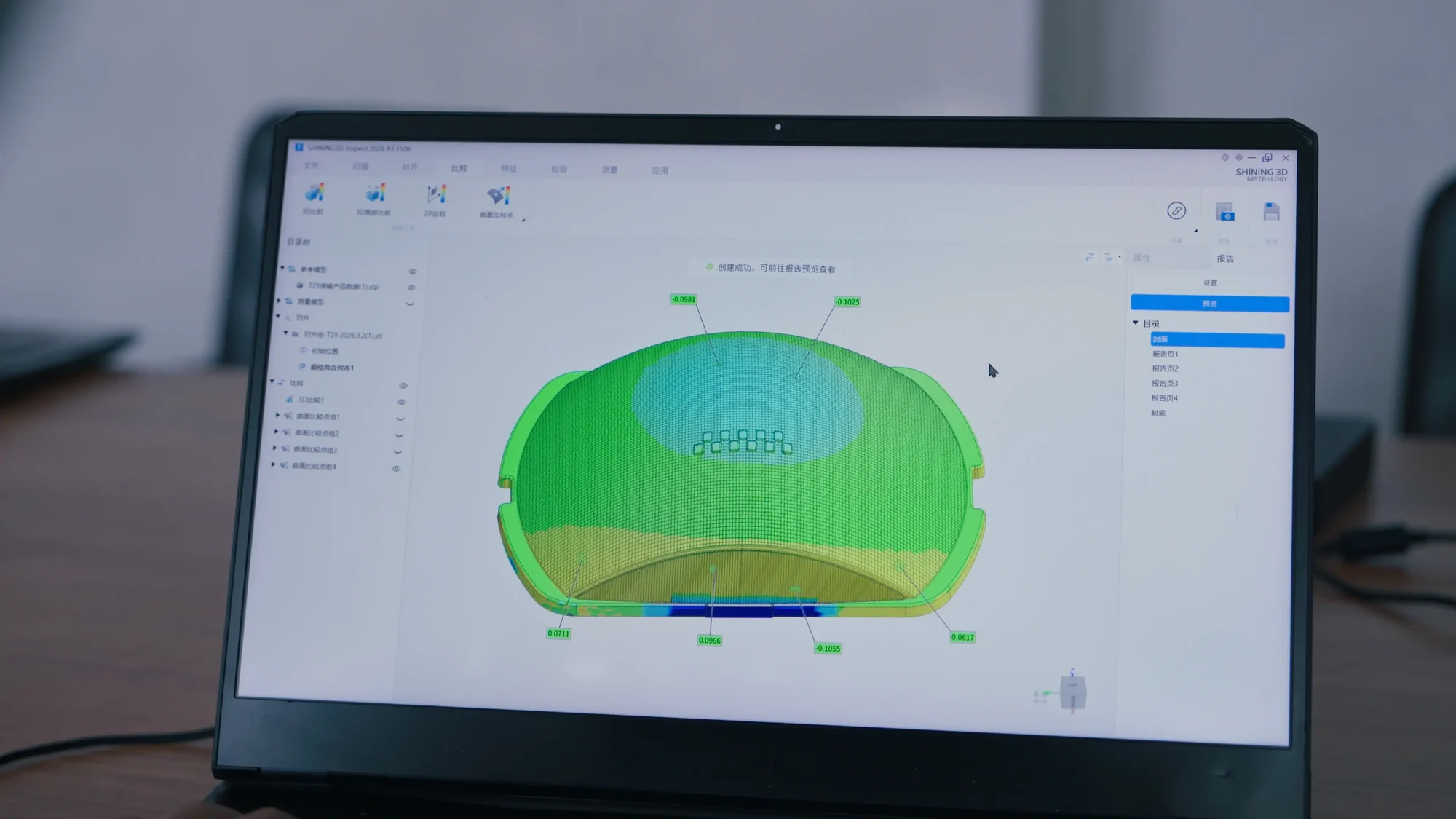
Automated and inline inspection. Robot cells move the head through a taught path, capture the same features on every unit, and generate comparable reports across a batch. RobotScan control software coordinates the robot, turntable and scanning sequence, which is what makes a cell repeatable rather than operator-dependent.
Reverse engineering. Reverse engineering extracts design information from an existing object and rebuilds it as an accurate digital model. The modern workflow runs from high-precision 3D scanning through CAD reconstruction in dedicated software to local manufacturing by CNC machining or additive processes, and it is used to recreate obsolete parts, correct wear on original geometry, and redesign legacy components. For structured light, the practical requirement is that the scanner resolves the smallest design feature that must appear in the rebuilt model.
Industrial-grade reliability and traceable accuracy in practice
Reliability in a metrology context is a documentation question as much as a hardware question. SHINING 3D operates an ISO/IEC 17025 accredited precision laboratory that performs dimensional calibration and inspection services, and calibrates scanners with certified artefacts or calibration panels traceable to metrology standards; certificates reference VDI/VDE 2634 and ISO 10360, subject to the actual certificates issued. Behind the products, the company holds a quality management system covering ISO 9001, ISO 14001, ISO 45001 and ISO 13485, product compliance including CE, FDA and FCC, AEO status for supply chain security, and information security certifications including TISAX and ISO/IEC 27001. For a manufacturing buyer, these documents reduce the audit load: the measurement evidence and the supplier quality evidence come from the same organisation.
Throughput: what recorded comparisons actually show
Caliper measurement is point by point and contact based: each feature is measured individually, the part is touched, and only the measured features are documented. Structured light and laser scanning capture the full surface in one acquisition, so the comparison is between complete workflows rather than between single readings. SHINING 3D case records show how large that difference can be, and how much it varies:
- EMI filter prototypes: a handheld metrology scanner replaced an internal laboratory process, reducing measurement time from an average of 3 to 4 days, or roughly two weeks when outsourced, to 2 to 3 hours.
- High-precision moulds and custom equipment: inspection time fell from 30 to 45 minutes to 10 to 15 minutes per part, with overall 3D inspection efficiency improving by approximately 60 percent.
- Automotive lighting and precision optics: complete 3D measurement data was captured within minutes instead of through sequential feature checks.
Read together, those records span a several-fold to roughly ten-fold reduction depending on part count, preparation and reporting. That range is consistent with the five-to-ten-times throughput difference commonly cited for scanning versus caliper-based key-point checks, but it is case-derived and conditional. The gain comes from eliminating per-feature handling and from producing a dataset that also supports CAD comparison, GD&T evaluation and reporting, not from scan speed in isolation.
Frequently asked questions
What certification and calibration documentation should come with a structured light metrology 3D scanner?
Ask for an acceptance test to VDI/VDE 2634 and ISO 10360 performed in an ISO/IEC 17025 accredited laboratory, plus a calibration certificate traceable to those standards, subject to the actual certificates issued. SHINING 3D tests its metrology scanners in its own ISO/IEC 17025 accredited accuracy laboratory and calibrates with certified artefacts or calibration panels traceable to metrology standards. The purpose of the paperwork is traceability: it connects a measurement result to a reference, which is what an internal quality system or a customer audit needs to see.
When is structured light a better fit than laser scanning on a shop floor?
Structured light is generally the stronger choice when small to medium parts with fine features, sharp edges, grooves and complex curved surfaces must be captured at high resolution, and when the part can be presented under controlled lighting on a fixture, turntable or robot cell. Laser line scanning is generally stronger when the surface is dark, shiny or reflective and cannot be sprayed, when the part is large and the scanner must travel to it, or when deep pockets need single-line access. Many plants use both: structured light for the high-detail inspection cell, and handheld or tracking laser systems for large and on-site work.
How should accuracy targets be set for small parts versus large assemblies?
Set the target from the tightest tolerance that must be verified, not from the smallest number available. The published SHINING 3D tiers are 0.005 to 0.02 mm for functional safety parts, strict GD&T and precision reverse engineering; 0.02 to 0.05 mm as a working band for assembly verification and structural analysis; and 0.05 to 0.1 mm for overall deformation analysis, surface deviation mapping and large cosmetic parts. For large objects, specify volumetric accuracy instead of a single-point figure: for a stated 0.02 mm + 0.015 mm/m, a 2 m feature implies 0.02 + (0.015 x 2) = 0.05 mm.
What budget range should a project plan for industrial inspection scanning?
SHINING 3D published guidance states that industrial inspection carries the highest accuracy requirements and the harshest production environments, with budgets typically starting from twenty thousand US dollars. Actual project cost depends on the configuration: a fixed structured light head, a robot cell with turntable and fixtures, software modules and calibration services are priced differently. Compare configured scope and included documentation rather than scanner prices alone, and confirm which software licences and calibration services are inside the quoted figure.
How do we validate a configuration on our own parts before committing?
Define a representative part set covering the smallest feature, the largest volume and the most difficult surface in the project. Ask for an acceptance test that follows the standards and the measuring volume you will use in production, and request the calibration certificate that will accompany the unit. Confirm software compatibility for the downstream workflow, whether that is SHINING3D Inspect for scan-to-report, or PolyWorks, Geomagic Control X, Geomagic Design X and EXModel for inspection and reverse engineering. SHINING 3D states a one-unit MOQ and offers customization covering logo and automation solution, which allows a single-cell trial before a line-wide rollout.
What lead time and support should an automated structured light cell be planned around?
SHINING 3D quotes a 30 to 45 day lead time, a one-unit MOQ, 100 percent testing before shipment, and remote or on-site after-sales support. Because a RobotScan cell is configured rather than catalogue-ordered, with robot brand, scanner, turntable, fixtures and control and inspection software all selectable, the configuration should be frozen before the lead-time clock starts. Project-specific questions can go through the SHINING 3D website, and the 3D digitizing introduction brochure summarises the wider portfolio for internal review.
Conclusion
Structured light metrology scanner selection reduces to a sequence: confirm the part fits the working volume, convert the drawing tolerance into an accuracy tier, set resolution from the smallest feature, specify volumetrically for anything large, verify the calibration chain behind the numbers, and only then compare form factors and automation levels. Structured light earns its place in smart manufacturing where complex and curved surfaces must be measured in full, repeatedly, and with an auditable accuracy claim; laser handheld and tracking systems take over where surfaces, part size or accessibility push beyond those conditions. A configuration is ready to order when the acceptance standard, the measuring volume, the software workflow and the throughput model have all been written down and tested on real parts.

Have Questions or Need More Details?
Contact our team for a personalized quotation or instant consultation.
Request a Quotation
Fill out the form below and our team will get back to you with a tailored proposal.
WhatsApp Direct Chat
Prefer to chat in real-time? Message us on WhatsApp for instant assistance & quick answers.
- Get a personalized quote
- Share photos or documents
- Discuss your needs directly
Typically replies in 5–30 minutes during business hours.