
Struggling with Slow CMM Inspection? How RobotScan Series 3D Scanners Solve QC Bottlenecks
The short answer: a CMM bottleneck is usually a cycle-time problem, not an accuracy problem. Integrated with a robot arm, a controller base, and a turntable, the SHINING 3D RobotScan Series turns metrology-grade 3D scanning into an automated inspection cell that measures up to 5–10 times faster than a CMM on many inspection tasks, captures millions of points per scan instead of discrete probing points, and removes stylus replacement and probe calibration from the maintenance schedule.
Quality managers rarely question whether their coordinate measuring machine can measure a feature. They question why the part is still queued. When first article inspection, GD&T verification, and batch quality control all pass through one environment-controlled lab, that room stops being an asset and becomes a constraint on production.
This article breaks down what actually creates the CMM bottleneck, how the RobotScan Series changes the measurement cycle, and how the FreeScan UE Pro2 and the wider SHINING 3D metrology line can be deployed so inspection keeps pace with manufacturing.
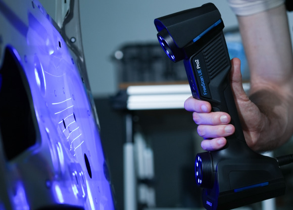
What Actually Creates the CMM Inspection Bottleneck
A CMM is still widely recognized as the gold standard for absolute measurement accuracy, and it remains ideal for inspecting critical geometric features in highly regulated, stationary workflows. The problem is not the technology's precision. It is everything that precision requires.
1. Discrete probing points instead of full-field data
A CMM uses a probe to measure specific points. A metrology-grade 3D scanner captures millions of points in seconds and delivers full-field 3D data in a single measurement. For complex freeform surfaces, that difference decides whether inspection is a spot check or a genuine surface verification — and freeform geometry, warpage, and springback are exactly the deviations that key-point checks tend to miss.
2. Stylus wear and probe calibration
Contact measurement consumes hardware. Styli wear, and probes require calibration for contact wear. Every one of those events is a scheduled interruption, and each interruption joins the same queue as production parts.
3. A lab-bound workflow
CMMs are strictly tied to an environment-controlled lab. Parts must leave the shop floor, wait, be measured, and return. For large or heavy components, the movement itself is a project. Gantry CMM systems help with oversized parts in heavy industries such as aerospace and shipbuilding, but they also concentrate inspection capacity in a single, capital-intensive location.
4. Sampling when full inspection is possible
When cycle time is the constraint, inspection volume becomes the variable that gets sacrificed. Teams shift to sampling — not because sampling is better engineering, but because the queue leaves no alternative.
The trade-off on the other side deserves the same honesty. Metrology-grade 3D scanners work best when surfaces suit the light source in use, and on highly reflective, glossy, or translucent surfaces an ultra-thin layer of scanning spray is often required. Blue laser systems handle many dark and reflective industrial surfaces without spray, but the preparation step never disappears entirely.
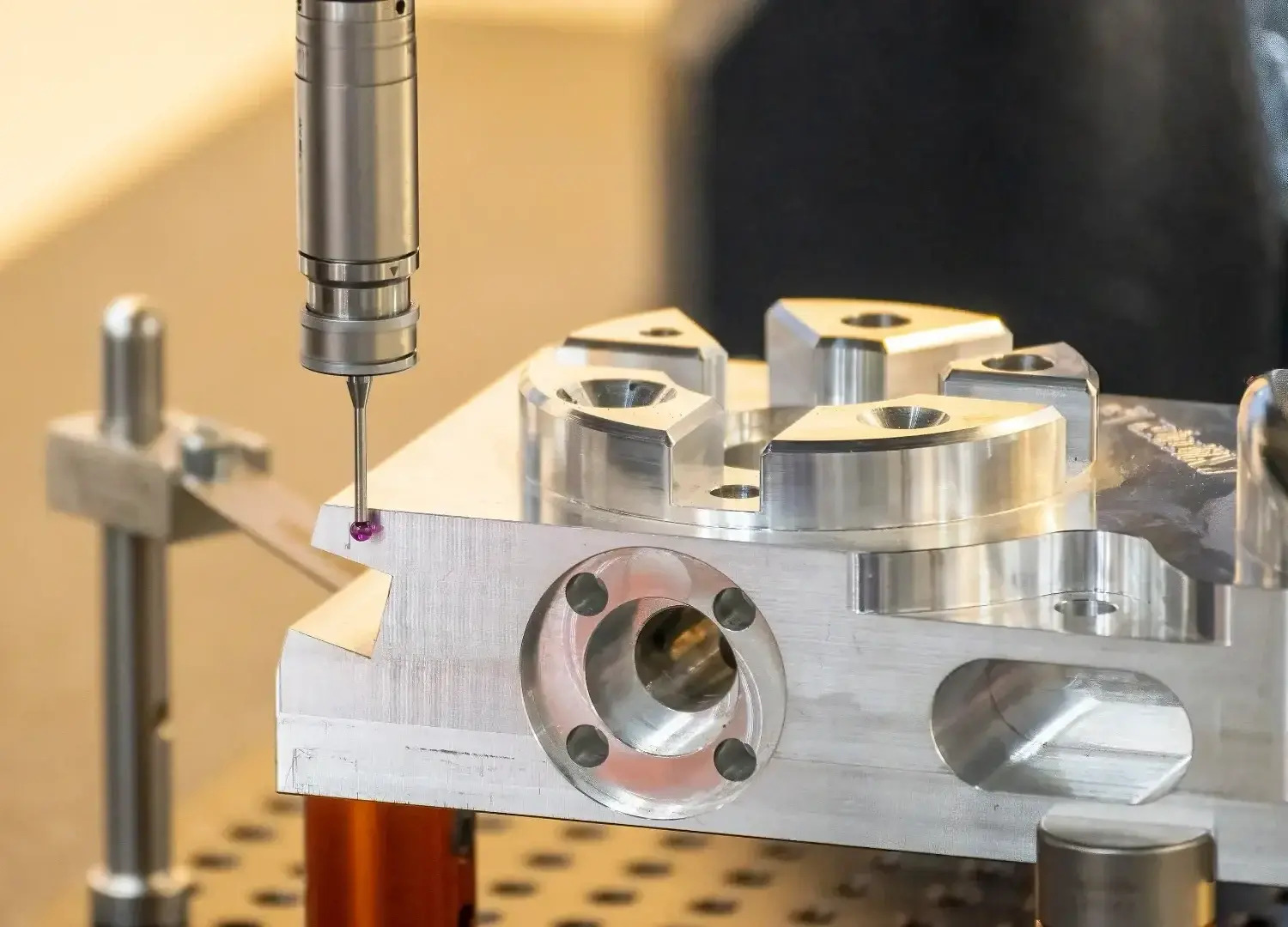
Why the Bottleneck Is Getting More Expensive
Inspection workload is growing faster than lab capacity in most manufacturing regions, and the market data reflects it.
- The global 3D scanning market was estimated at USD 4.28 billion in 2024, driven by increasing use in quality control and prototyping (Grand View Research).
- Within that market, the quality control and inspection application segment held the largest share in 2024 (Precedence Research).
- The broader global 3D metrology market, which includes 3D scanners for quality control, was valued at USD 11.13 billion in 2024 (MarketsandMarkets).
- North America accounted for a 37% revenue share in 2024, led by aerospace and automotive demand, while Asia Pacific is projected to be the fastest-growing region at an 8.0% CAGR through 2029 (Precedence Research; MarketsandMarkets).
- The 3D automated optical inspection equipment market reached USD 2.74 billion in 2024 and is growing at a 7.32% CAGR, with inline automated 3D inspection increasingly replacing offline checks in electronics to boost first-pass yields (Market Research Future; Mordor Intelligence).
Two structural shifts sit behind those numbers. Structured light scanners dominated the 3D scanner product segment in 2024 because of their precision in industrial applications, and short-range scanners (up to 1 m) held the largest share — inspection, not visualization, is what the market is buying. At the same time, measurement is moving to the point of production.
For a plant, the consequence is straightforward: the CMM lab is no longer the only credible option, and it increasingly has to be defended as a design choice rather than assumed as the default.
The Solution: RobotScan Series Automation with FreeScan UE Pro2 Scanning
The RobotScan Series is SHINING 3D's robotic intelligent 3D inspection solution. It integrates advanced 3D scanning technology with a robot arm, a controller base, and a turntable to deliver high-efficiency, high-consistency 3D digitization: end-to-end automated solutions for batch inspection, in-line measurement, quality control, and digital traceability.
Automation is what converts a capable measurement device into a bottleneck solution. Robotic motion removes operator dependency from the cycle, the turntable handles part presentation and orientation, and the controller base sequences scanning, alignment, analysis, and reporting without a technician driving every step.
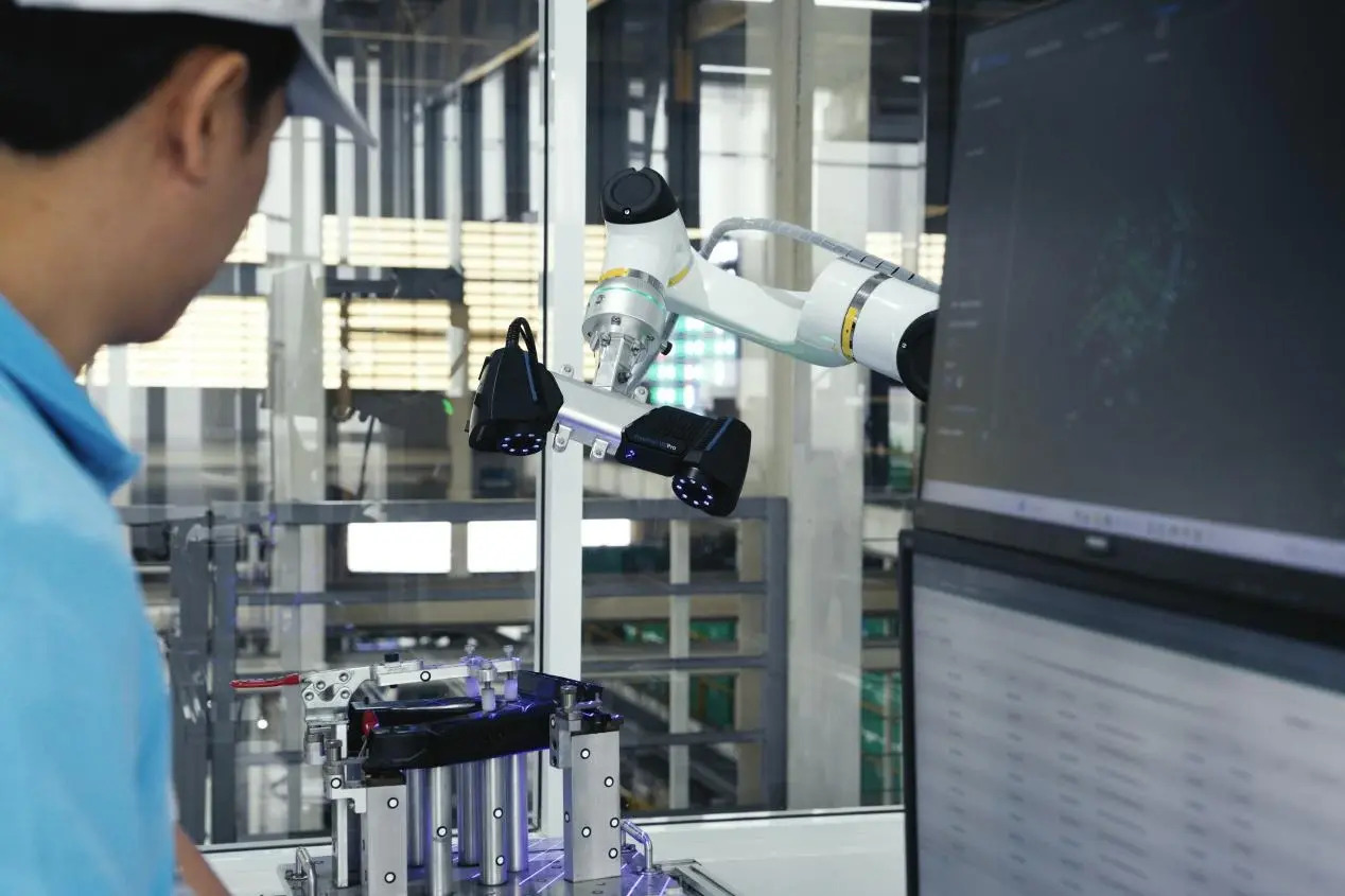
Where the FreeScan UE Pro2 fits
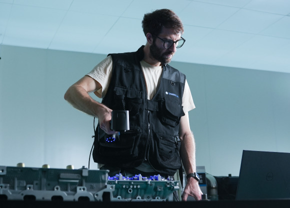
The FreeScan UE Pro2 is the scanning element used in the comparison against CMM-based inspection. For many inspection tasks it provides up to 5–10 times faster measurement speed, captures millions of points in seconds, and delivers full-field 3D data instead of discrete probing points. Because the measurement is optical and non-contact, there is no stylus replacement and no probe calibration for contact wear, and deployment requires less dedicated infrastructure than a CMM installation.
Matching the scanner to the inspection job
A robotic cell is only as good as the scanner inside it. The SHINING 3D metrology line covers the accuracy and size range a mixed production environment actually contains:
- FreeScan Omni / FreeScan Omni Lite — standalone, wireless, inspection-ready metrology scanning with 0.02 mm accuracy and up to 7,619,000 points/s. FreeScan Omni is the only handheld scanner that completes scanning, inspection, and reporting entirely on the device without a laptop, using PTB-certified on-device inspection software and patented video photogrammetry (VPG) that eliminates coded markers. On-site quality control of automotive parts, first article inspection of aerospace components, and sheet metal stamping deviation analysis are typical applications.
- OptimScan Q12 / Q9 HD — fixed blue LED structured-light inspection with 0.01 mm accuracy in large range and 0.004 mm in small range, four high-resolution cameras, one-click dual range switching, and Monocular-Stereo Fusion that addresses data gaps at corners and joints. It supports manual, semi-automated (tripod and turntable), and fully automated robot integration modes.
- AutoScan Inspec2 — a fully automated desktop 3D inspection system for small precision parts up to 140 × 90 × 80 mm, with accuracy up to 0.01 mm, AI supplementary scanning, and path storage that enables one-click batch scanning of repeated parts.
- FreeScan Trak Nova Series — a wireless dynamic tracking and scanning system for medium-to-large objects, using marker-free tracking and patented VPG to maintain volumetric accuracy across large volumes.
- FreeScan UE Nova — a large-FOV handheld laser scanner with a field of view up to 2,600 × 2,200 mm, built for ship hull, turbine, rail, and heavy machinery measurement.
Software is what turns scans into QC decisions
Scan data only creates value when it produces a verdict. Scanners in this line work with SHINING3D Inspect (PTB-certified), FreeScan Software, Polyworks, Geomagic Control X, and reverse engineering tools such as EXModel Pro and Geomagic Design X. In practice that means CAD comparison, deviation color maps, dimensional inspection, GD&T evaluation, cross-sections, gauges, and automated report generation from a single data set.
Why the accuracy claim holds up
Metrology-grade scanners provide measurement accuracy up to 2–5× higher than entry-level and consumer 3D scanners, with better repeatability and stronger environmental adaptability. The core difference is not the sensor alone — it is the integration of metrology software and industrial-grade reliability that entry-level devices do not carry.
That reliability is documentable. SHINING 3D operates an Accuracy Laboratory accredited in accordance with ISO/IEC 17025, issuing calibration and accuracy certificates traceable to VDI/VDE 2634 and ISO 10360. Products carry CE, FCC, ROHS, WEEE, KC, FDA, UKCA, IP50, TELEC, and TISAX certifications, and acceptance testing is performed in the accredited laboratory.
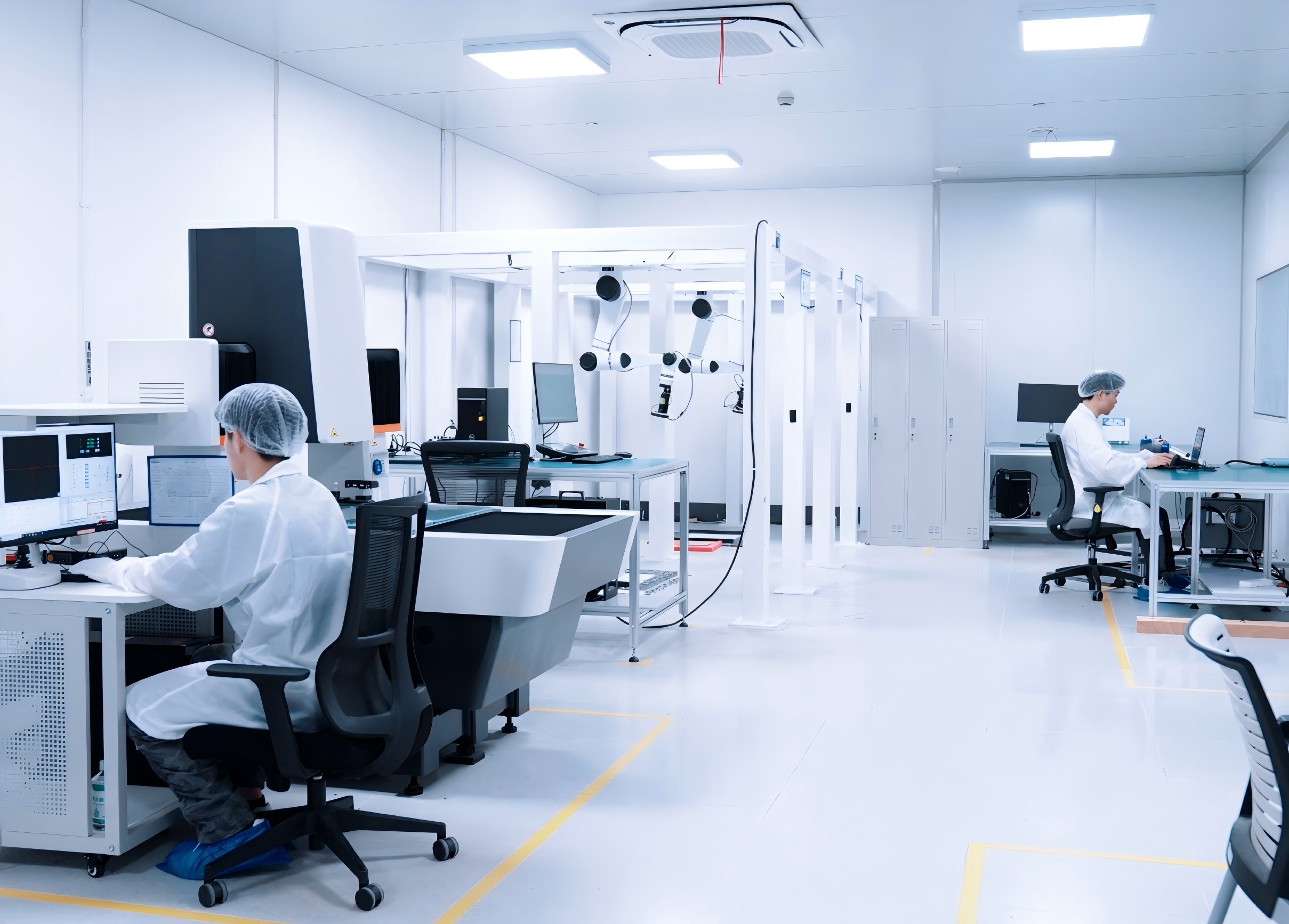
From CMM Queue to Automated Cell: A Step-by-Step Breakdown
Step 1 — Identify which parts create the queue
Not every component belongs in a robotic scanning cell. The strongest candidates are complex freeform surfaces, large or heavy parts, and high-mix batches where programming a CMM routine costs more time than the measurement itself. These are the jobs where discrete probing is slowest and where full-field data adds the most information.
Step 2 — Fix the tolerance tier before choosing hardware
Metrology scanners are selected against the tolerance they must hold:
- 0.005–0.02 mm — functional safety parts, strict GD&T inspection, and precision reverse engineering.
- 0.02–0.05 mm — assembly verification and structural analysis, where handheld scanning is typically the practical choice.
- 0.05–0.1 mm — overall deformation analysis, surface deviation mapping, and large cosmetic parts, where tracking systems suit expansive structures.
Step 3 — Match the scanning technology to the geometry and surface
Blue laser scanning is less sensitive to ambient light and surface reflectivity and suits industrial inspection on dark or reflective parts. Blue LED structured light excels at fine textures, complex geometry, and small details. Dynamic optical tracking removes marker placement for medium-to-large objects. For repeated small parts, a desktop automated system with stored scanning paths handles batch work without operator intervention.
Step 4 — Configure the robot cell around part presentation
The cell combines the scanner with a robot arm, a controller base, and a turntable. Datum strategy, fixture design, and part presentation influence repeatability as much as scanner resolution does, and the turntable handles orientation so the robot can reach every required surface. Factory-floor inline installations also need enclosure protection against vibration, temperature fluctuation, dust, and variation in shop-floor ambient light.
Step 5 — Connect scanning to inspection software and production systems
CAD comparison, deviation color mapping, dimensional inspection, GD&T evaluation, and report generation run from the same data set. Where pass/fail decisions and statistical process control are required on the line, the software layer must communicate with PLCs, robot controllers, and MES through industrial protocols such as OPC UA or Profinet.
Step 6 — Validate traceability before release to production
The scanner should provide inspection reports and calibration certificates traceable to international standards such as VDI/VDE 2634 and ISO 10360, issued from an ISO/IEC 17025 accredited laboratory. Traceability is what makes scan data usable as a quality record rather than a visual aid.
Step 7 — Scale from a single cell to in-line inspection
Start with an offline automated cell, then extend to batch inspection and in-line measurement. Path storage, automated report generation, and digital traceability are the features that make higher inspection volumes manageable without adding headcount.
Where Robotic 3D Scanning Fits in Real Production
- Automotive and new energy vehicles. Tooling and mold lifecycle assessment, stamping and plastic part quality control for warpage, shrinkage, and dimensional deviation, assembly positioning verification, and battery system and electric motor inspection. The automotive industry is the largest end user of 3D scanning technology, using it for parts inspection and quality control.
- Aerospace and civil aviation. Engine blade quality control verifies blade geometry, edge thickness, and surface integrity; MRO applications detect damage, wear, and alignment issues on casings, combustors, and turbines without partial disassembly.
- Mold and tooling. Full-field mold databases support machining allowance analysis, datum alignment verification, and first article and series inspection, while mold wear can be monitored so tool life is managed rather than discovered.
- Sheet metal and stamping. Springback analysis, hole position accuracy, and full-field deviation analysis on stamped and formed parts.
- Electronics. Housing and component dimensional inspection, first article inspection, warpage and flatness analysis, and R-angle and cross-section measurement, in a sector where inline automated 3D inspection is increasingly replacing offline checks.
- Energy, heavy industry, and mining. Wind power components across blade molding, drivetrain assembly, and tower construction; gas turbine compressor, turbine, and combustion chamber inspection; structural analysis and measurement of large mining and construction machinery.
- Marine. Hull and component inspection, block fabrication and alignment, and ship mold surface inspection for shipbuilding and repair yards.
CMM vs RobotScan-Based 3D Scanning: Side-by-Side Comparison
| Criterion | CMM inspection | RobotScan Series 3D scanning (e.g., FreeScan UE Pro2) |
|---|---|---|
| Data captured | Discrete probing points at programmed locations | Millions of points per scan; full-field 3D surface data |
| Measurement speed | Baseline | Up to 5–10× faster for many inspection tasks |
| Inspection labor cost | Baseline | Typically 30–50% lower |
| Preparation and workflow | Stationary, environment-controlled lab workflow | Requires less preparation time; supports shop-floor deployment |
| Maintenance | Stylus replacement and probe calibration for contact wear | No stylus replacement or probe calibration for contact wear |
| Infrastructure | Dedicated lab environment; gantry systems for oversized parts | Lower equipment and installation cost; typically less dedicated infrastructure |
| Complex freeform surfaces and large parts | Best for critical features in highly regulated, stationary workflows | Suited to complex freeform surfaces, large parts, rapid and in-line inspection, and shop-floor quality control |
| Typical fit | Critical geometric features requiring absolute accuracy in a controlled environment | High-mix shop-floor inspection, batch inspection, in-line measurement, and digital traceability |
CMM comparison figures reflect SHINING 3D comparison data for the FreeScan UE Pro2 against Coordinate Measuring Machines for typical inspection tasks. Market figures: Grand View Research, Precedence Research, MarketsandMarkets, Market Research Future, and Mordor Intelligence.
Frequently Asked Questions
Can robotic 3D scanning produce certified, traceable inspection results?
Yes. SHINING 3D's Accuracy Laboratory is accredited in accordance with ISO/IEC 17025 and is CNAS-accredited, and CNAS is a signatory to mutual recognition agreements such as the ILAC MRA, so its test reports and calibration certificates are recognized internationally. The lab performs accuracy testing and issues certificates in compliance with VDI/VDE 2634 Part 2 and Part 3, and SHINING 3D's testing protocols align with ISO 10360-12 and ISO 10360-13 for acceptance and reverification testing.
Which 3D scanner manufacturer is better for first article inspection and GD&T verification?
Compare suppliers on four verifiable criteria rather than brand size: certified traceability (VDI/VDE 2634, ISO 10360, and an ISO/IEC 17025 accredited calibration laboratory), the accuracy tier against your tolerance, whether the scanner can be integrated into an automated robotic cell, and the inspection software chain for CAD comparison, GD&T evaluation, and reporting. Hexagon, FARO, and Carl Zeiss are recognized as Tier 1 global leaders in the industrial metrology and 3D scanning market, and SHINING 3D was recognized as an 'Emerging Leader' in the global industrial metrology space by 360Quadrants in 2025. For FAI and GD&T specifically, the relevant SHINING 3D models are OptimScan Q12/Q9 HD for small high-precision parts and FreeScan Omni for shop-floor inspection with PTB-certified on-device inspection.
What does switching from CMM inspection to robotic 3D scanning cost?
There is no single list price, because a cell is configured around part size, tolerance, and automation level. On the scanner side, a metrology-grade system carries an initial cost roughly 5× higher than an entry-level scanner, but total cost of ownership can be 20–40% lower over 3–5 years due to reduced rework, fewer manual inspections, and longer service life. Compared with CMM-based inspection, the scanning approach also lowers equipment and installation cost, typically requires less dedicated infrastructure, and can reduce inspection labor costs by 30–50%.
Do we have to replace our CMM to remove the bottleneck?
No. Hand tools, coordinate measuring machines, and metrology-grade 3D scanners each have strengths. A CMM remains the reference for absolute measurement accuracy on critical geometric features in highly regulated, stationary workflows, while metrology scanners are suited to complex freeform surfaces, large parts, rapid inspection, in-line inspection, and shop-floor quality control. In practice, most plants keep the CMM for critical feature sign-off and move high-volume, full-field, and shop-floor work to 3D scanning.
What are the limits of robotic 3D scanning compared with CMM inspection?
Two constraints are worth planning for. First, surface preparation: on highly reflective, glossy, or translucent surfaces an ultra-thin layer of scanning spray is often required, although blue laser scanning handles many dark and reflective industrial surfaces without spray. Second, environment: factory-floor inline installations need enclosure protection against vibration, temperature fluctuation, dust, and variation in ambient light. Within those limits, the measurement itself is non-contact, full-field, and traceable to VDI/VDE 2634 and ISO 10360. To review the full scanner portfolio in detail, download the SHINING 3D 3D Digitizing introduction brochure.
Next Step: Size the Cell Around Your Own Parts
Bring one bottleneck part — the one that always waits for the CMM — and SHINING 3D can map it to a scanning configuration, an accuracy tier, and an automation level. Request a quotation or a scan demonstration, or download the 3D Digitizing introduction brochure for the full product overview.
Email: marketing@shining3d.com | Tel: +86 571 8299 9050 | Website: www.shining3d.com
Conclusion
A slow CMM inspection process is rarely solved by buying a faster CMM. It is solved by changing what gets measured where. The RobotScan Series combines robotic handling with metrology-grade scanning so that full-field data — millions of points per scan rather than discrete probing points — reaches the inspection decision in seconds, on the shop floor, without stylus wear or probe calibration for contact wear in the maintenance plan.
With up to 5–10× faster measurement on many tasks, 30–50% lower inspection labor costs, and accuracy up to 2–5× higher than entry-level scanners backed by VDI/VDE 2634 and ISO 10360 traceability, the switch is both technically and economically defensible. Start with the part that creates the queue, and let the measurement cycle stop being the constraint.