
Top 3D Scanning Solutions for Quality Control: Rankings and Selection Criteria
Quality control is now the single largest application segment of the 3D scanner market, and the reason is practical: a 3D scanner for quality control answers questions that hand tools and key-point gauges cannot — what the whole surface actually looks like, and where it deviates from nominal. The problem is that “3D scanner” describes everything from a hobbyist desktop device to a metrology-grade system certified under VDI/VDE 2634 and ISO 10360, and those tools are not interchangeable in a quality function.
This guide ranks the six professional solution classes that SHINING 3D builds for quality control work, ordered by how much traceable measurement value they deliver per inspection scenario, and then sets out the selection criteria that decide which class belongs on your shop floor. The ranking is deliberately based on documented specifications, certified accuracy, and published application results — not on marketing claims.
Short answer: rank QC scanning solutions by six criteria in this order — traceable specified accuracy, measurement volume versus part size, repeatability under production conditions, environmental adaptability, inspection software and workflow fit, and automation readiness. Professional systems outrank consumer models primarily because their data carries metrological traceability and repeatability, not because they produce prettier models.
The Quality Control Problem: Why Scanner Choice Decides the Inspection Outcome
Most quality-control scanning failures trace back to three mismatches.
The tolerance mismatch. If a drawing calls out a tolerance tighter than the scanner’s specified accuracy, the resulting inspection report cannot support an accept/reject decision. Accuracy is how closely a measured result matches the true dimension: if a 100.00 mm feature is measured as 100.02 mm, the error is 0.02 mm. Smaller measurement errors mean higher accuracy.
The traceability gap. Consumer and hobbyist 3D scanners efficiently generate visually appealing 3D models and are cost-effective for visual digitalization and design assistance, but their data lacks strict metrological traceability and cannot be used to sign off on engineering quality reports. That single distinction — not resolution, not point count — is why professional systems outrank consumer models in a quality function.
The volume and environment mismatch. A system that measures small parts beautifully in a temperature-controlled lab may be physically unable to capture a one-metre casting on a production floor, or may accumulate errors that grow with distance. Volumetric accuracy captures this effect: it describes measurement accuracy across an entire scanning volume rather than at individual points. A scanner specified at 0.02 mm + 0.015 mm/m, used on a 2-metre-long object, should be read as 0.02 + (0.015 × 2) = 0.05 mm maximum error over the full length.
Repeatability is the second half of the picture. Precision, also called repeatability, measures how consistently a scanner reproduces the same measurement under unchanged conditions. Scanning a 100.00 mm machined part five times and reading 100.02, 100.02, 100.03, 100.02, and 100.02 mm shows a 0.01 mm spread — excellent repeatability, even though the readings sit slightly off the true value. In production QC, repeatability is what makes a measurement system usable for trend monitoring and pass/fail limits.
Industry Background: Where 3D Scanning for Quality Control Stands in 2026
The demand context is well documented. According to Precedence Research, the quality control and inspection application segment held the largest share of the 3D scanner market in 2024, and the automotive industry is the largest end-user, applying the technology to parts inspection and quality control. Structured light scanners dominated the 3D scanner product segment in 2024 because of their high precision in industrial applications, while short-range scanners (up to 1 metre) held the largest share of the market, driven by precision requirements in parts inspection.
Market sizing depends on definition, and the divergence is worth stating openly. Grand View Research estimated the global 3D scanning market at USD 4.28 billion in 2024, while Precedence Research valued the narrower 3D scanner market at USD 1.98 billion for the same year. The broader 3D metrology market, which includes scanners, CMMs, and sensors, was valued at USD 11.13 billion in 2024 by MarketsandMarkets. Regionally, North America held a 37% revenue share of the 3D scanner market in 2024, led by aerospace and automotive demand, while Asia Pacific is projected to be the fastest-growing region for 3D metrology at a CAGR of 8.0% through 2029. Separately, the 3D automated optical inspection (AOI) equipment market reached USD 2.74 billion in 2024 and is growing at a 7.32% CAGR, reflecting a broader industry shift in which inline automated 3D inspection systems increasingly replace offline checks in the electronics sector to raise first-pass yields.
Two standards shape how buyers should read accuracy claims. ISO 10360-12:2016 is the international standard specifically for verifying the performance of articulated arm CMMs equipped with 3D scanners, and VDI/VDE 2634 Part 3 is the guideline for acceptance and reverification of optical 3D measuring systems based on multiple-view area scanning. A supplier that can issue calibration and accuracy documentation referencing these frameworks gives a quality team something auditable.
The vendor landscape is tiered. SNS Insider recognised Hexagon, FARO, and Carl Zeiss as Tier 1 global leaders in industrial metrology and 3D scanning, and SHINING 3D was recognised as an “Emerging Leader” in the global industrial metrology space by 360Quadrants in 2025. SHINING 3D, established in 2004 and headquartered in Hangzhou, China, reported operating revenue above USD 220 million in 2025 and 31% revenue growth for that year, with subsidiaries in Stuttgart, Barcelona, California, Florida, and Tokyo. Its accuracy laboratory is accredited in accordance with ISO/IEC 17025, which is the basis for issuing traceable calibration and verification results.
The Rankings: Six Professional 3D Scanning Solution Classes for Quality Control
The ranking below is ordered by breadth of quality-control coverage: how many inspection scenarios a class can serve with certified accuracy, how well it survives real production environments, and how directly it produces an inspection decision rather than just data. Across the professional classes, specified accuracy steps by roughly 3.6× to 5× per class (0.072 mm → 0.02 mm → 0.004 mm), and each step changes which inspection tasks are technically defensible.
Rank 1 — Wireless standalone handheld metrology scanner: FreeScan Omni / FreeScan Omni Lite
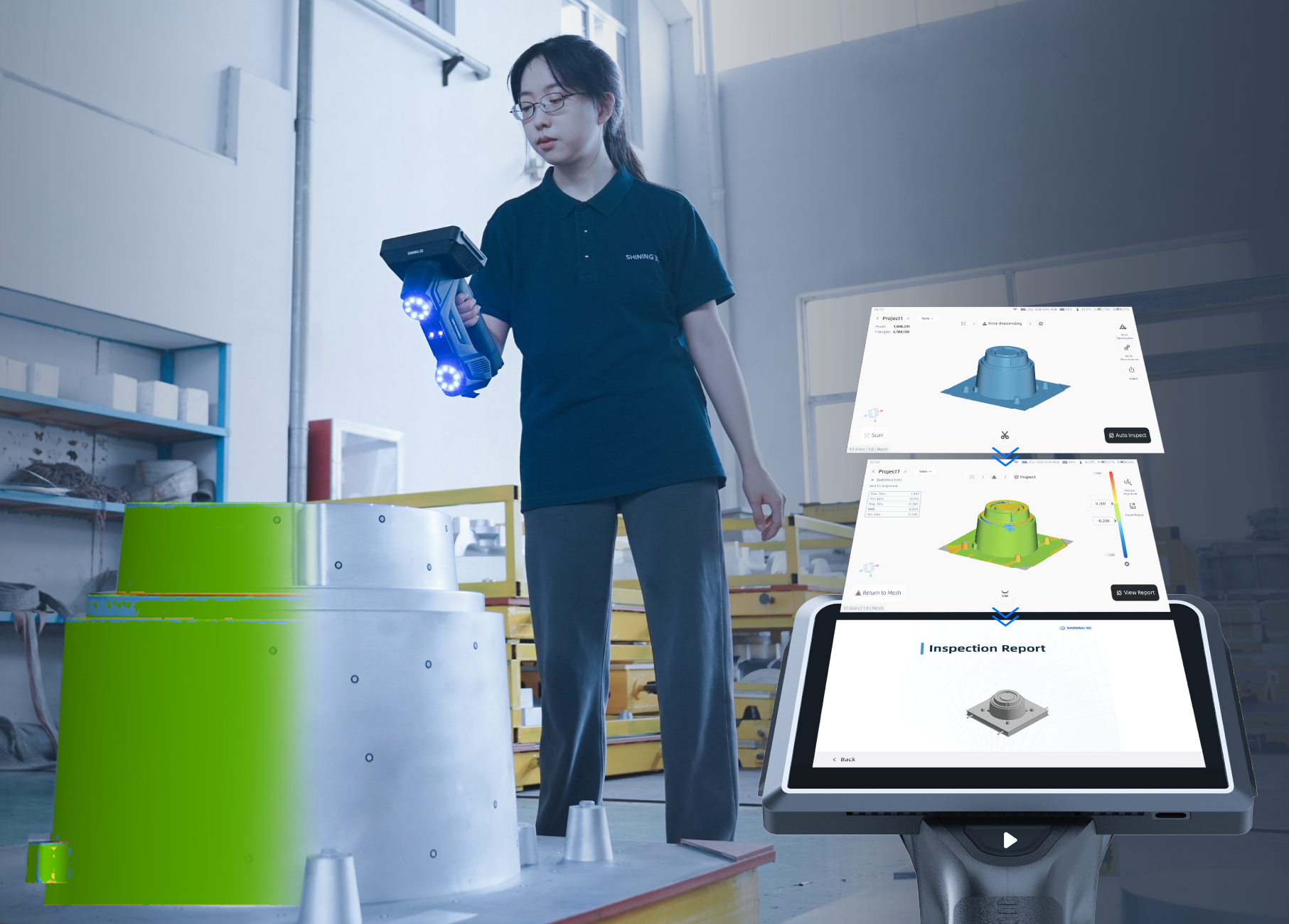
Ranked first because it removes the two biggest practical constraints in shopfloor quality control: the laptop and the cable. FreeScan Omni is a standalone, wireless, inspection-ready metrology 3D scanner with certified accuracy of 0.02 mm, volumetric accuracy of 0.02 + 0.03 mm/m, and 0.02 + 0.015 mm/m when Video Photogrammetry (VPG) is applied. Scan speed reaches 7,619,000 points/s, with a laser field of view of 580 × 650 mm and an infrared field of view of 1205 × 1104 mm.
Its differentiator for QC is on-device inspection: scanning, inspection, and reporting complete on the device without a laptop, using the PTB-certified SHINING3D Inspect module. AI feature recognition measures holes and slots, intelligent hole boundary detection supports hole scanning, and four scan modes — 93 laser lines for high speed, 25 parallel lines for detail, single-line for deep pockets, and IR rapid scan for marker-free capture — cover mixed geometry in one device. Accuracy is certified to VDI/VDE 2634 Part 3 and aligned with ISO 10360, tested in the ISO/IEC 17025 accredited laboratory. At ≤1.1 kg with hot-swappable batteries, it moves to the part instead of moving the part to a measuring room.
Limits to plan for: the package ships with eight rechargeable batteries providing up to one hour of continuous scanning per set; wireless connectivity handles data transmission only and does not affect accuracy.
Rank 2 — Fixed structured-light inspection system: OptimScan Q12/Q9 HD and OptimScan Q12/Q9
Ranked second because it holds the tightest accuracy in the portfolio and is the correct answer whenever the tolerance is the hard constraint. The OptimScan Q12/Q9 HD is a high-precision blue LED 3D inspection scanner with 0.004 mm accuracy in small-range mode and 0.01 mm in large-range mode, four high-resolution cameras (Q12 HD: 4 × 12.3 MP; Q9 HD: 4 × 9 MP), dual scan range with one-click switching, and Monocular-Stereo Fusion (MSF) technology that increases data coverage at corners and joints. Single-shot capture is under one second. The standard OptimScan Q12/Q9 specifies 0.005 mm in small range and 0.015 mm in large range, with 4 × 12.3 MP or 4 × 9 MP cameras respectively. Both families are accepted to VDI/VDE 2634 Part 2 and ISO 10360, tested in the ISO/IEC 17025 accredited laboratory.
For quality control this class serves geometrical surface inspection of small and medium precision parts, GD&T analysis, and mold wear inspection, where a 0.004 mm specification is what makes the measurement defensible. Three operation modes — manual, semi-automated with tripod and turntable, and fully automated with industrial robot integration — allow the same unit to start as a lab instrument and later become part of an automated inspection cell. OptimScan Q12/Q9 is documented as compatible with the RobotScan robotic intelligent 3D inspection system.
Limits to plan for: fixed systems suit repetitive, high-precision scanning of smaller parts in controlled environments; handheld scanners remain the better fit for large, complex, or hard-to-reach parts. These units do not capture colour texture, and highly reflective, glossy, or translucent surfaces may still require an ultra-thin layer of scanning spray.
Rank 3 — Automated robotic in-line inspection cell: RobotScan Series
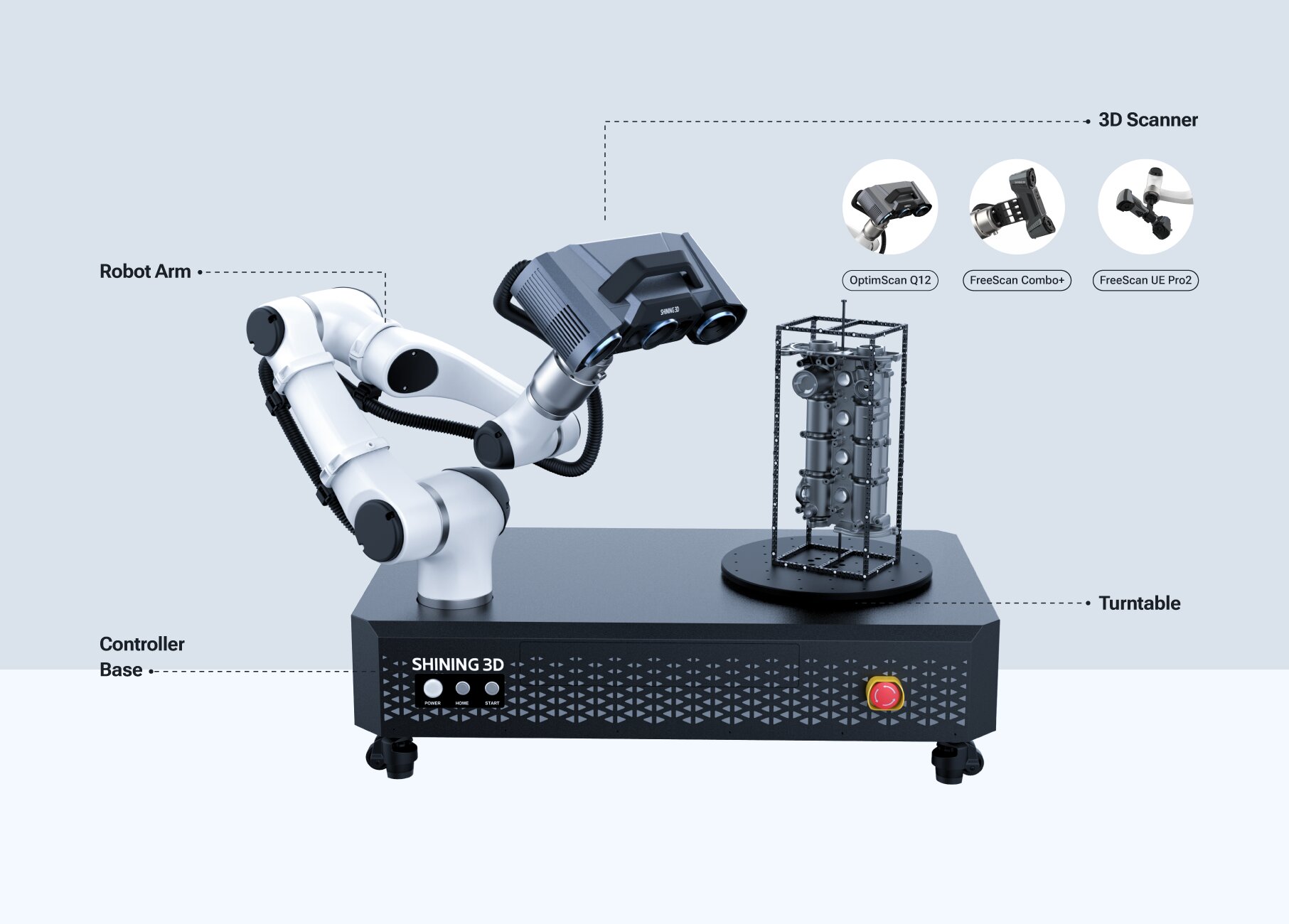
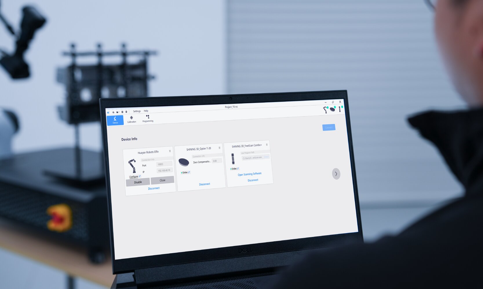
Ranked third because it converts inspection from a manual, labour-intensive task into a standardized, automation-ready process. The RobotScan Series combines a high-accuracy 3D scanner with an industrial or collaborative robot, a controller base, a turntable, fixtures, and control and inspection software into an end-to-end automated solution for batch inspection, in-line measurement, quality control, and digital traceability. Documented system parameters include measurable object size up to 500 mm, turntable load capacity up to 20 kg, robot working radius of 800 mm, and a system weight of 70 kg.
Three documented configurations cover different part mixes. RobotScan Q12 uses fringe projection technology for high detail on small parts with complex surfaces, geometries, or sharp edges — airfoils, brackets, connectors, gears, housings, and electronic components — targeting high repeatability and high efficiency in mass-production inspection. RobotScan UE Pro2 uses handheld blue laser scanning technology with strong material adaptability to black, shiny, and reflective surfaces, suited to small and medium sheet metal parts, casting housings, machining parts, and mold components, with wireless and wired connectivity for flexible on-site integration. RobotScan Combo+ uses a hybrid light source for mixed-size components such as covers, trim pieces, assemblies, and medium castings. Configurations are customizable across robot arm brand, SHINING 3D scanner, turntable, fixtures, and software.
Limits to plan for: automated cells suit repetitive, high-volume geometries within the stated envelope; one-off, oversized, or highly variable parts are usually better served by a handheld or tracking system.
Rank 4 — Dynamic tracking system for large volumes: FreeScan Trak Nova Series
Ranked fourth because it solves the problem that most limits large-part QC: accuracy that degrades with distance. FreeScan Trak Nova Series is a wireless multi-functional dynamic tracking and scanning system with 0.02 mm accuracy, volumetric accuracy of 0.062 mm over 12 m³, and 0.046 mm + 0.012 mm/m when VPG is applied. Scan speed reaches 7,600,000 points/s, flexible field of view extends to 2600 × 2200 mm, and the system includes 62-line high-speed scanning, 25 parallel-line detailed scanning, and single-line deep-pocket scanning. The tracker can also be operated independently as a large-FOV handheld laser scanner, so one system covers multiple tasks.
Its documented value in QC is marker-free operation for most parts and stable volumetric accuracy on large structures, with batteries supporting up to 2.5 hours in wireless mode for the TE Nova configuration. Real deployments illustrate the effect: a hydro-turbine metrology service provider in the United States digitised an 8-foot clarifier cover in a single day using this system; an Australian steel manufacturer reduced inspection of a 15-ton trommel screen shell from days to hours, comparing scan data against the original CAD model to identify deviations outside manufacturing tolerances before refurbishment.
Limits to plan for: markers may still be recommended on very large surfaces to ensure optimal accuracy, and a Wi-Fi router is required for wireless operation (a Wi-Fi 6 router is recommended if supplying your own).
Rank 5 — Wireless hybrid handheld scanner: FreeScan Combo+ Wireless / FreeScan Combo Wireless
Ranked fifth for its combination of portability and material tolerance. FreeScan Combo+ Wireless is a wireless hybrid light source metrology handheld 3D scanner using Wi-Fi 7 for industrial-grade wireless data transmission with anti-interference technology, specified at 0.02 mm accuracy, 0.02 + 0.03 mm/m volumetric accuracy, and 0.02 + 0.015 mm/m with VPG. It delivers up to 9,106,000 points/s with 93 laser lines at 180 FPS, in a 550 g body measuring 189 × 81 × 53 mm, with up to 2 hours of continuous scanning on a hot-swappable battery. Five scan modes cover high-speed, detailed, deep-pocket, and IR marker-free scanning, and the integrated inspection workflow includes real-time mesh display, AI feature recognition for holes and slots, intelligent resolution, and data quality visualisation.
This class is the practical choice for shopfloor inspection and deviation inspection in confined or awkward spaces, where a cable is a genuine obstacle and surface finishes are dark, shiny, or reflective.
Limits to plan for: the FreeScan Combo Series does not include a colour camera, so texture information is not captured; accuracy remains 0.02 mm, so it does not replace a fixed system for sub-5-micron work.
Rank 6 — Automated desktop system for small parts: AutoScan Inspec2
Ranked sixth because it specializes narrowly, and specializes well. AutoScan Inspec2 is a fully automated desktop 3D inspection system for small precision parts, with accuracy up to 0.01 mm (10 microns), two 5 MP industrial cameras, a maximum scan range of 140 × 90 × 80 mm, blue LED light source, and a 5 kg / 420 × 260 × 270 mm footprint. Its workflow advantages are AI supplementary scanning with intelligent path planning, path storage that enables batch scanning of repeated parts with one-click operation, a multi-object mode that scans eight objects at once, full-colour texture capture, and a seamlessly integrated PTB-certified SHINING3D Inspect module for 3D comparison, GD&T measurement, and report generation.
Where a facility runs repeated first article inspection or production quality control on electronic components, small mechanical parts, medical devices, or jewelry, this is the lowest-friction route to repeatable results without operator dependency.
Limits to plan for: parts must fit the 140 × 90 × 80 mm field of view; larger workpieces belong in another class.
Not ranked: consumer and entry-level scanners in a quality function
Consumer and hobbyist 3D scanners remain useful for visual digitalization, basic design assistance, and digital asset creation. They are not ranked here because their data lacks strict metrological traceability, which disqualifies them from signing off engineering quality reports. This is the core reason professional systems outrank consumer models: not raw point count, but metrology software and repeatability — acceptance-testing traceable to standards such as VDI/VDE 2634 and ISO 10360, performed in an ISO/IEC 17025 accredited laboratory, and inspection software such as the PTB-certified SHINING3D Inspect, alongside PolyWorks and Geomagic Control X.

Step-by-Step Selection Framework: Seven Decisions Before You Buy
Step 1 — Fix the tolerance and map it to an accuracy tier. Accuracy requirements group into three practical tiers. From 0.005 to 0.02 mm is required for functional safety parts, strict GD&T inspection, and precision reverse engineering, where high-resolution cameras help capture sharp edges on tiny features. From 0.02 to 0.05 mm is the standard tolerance band for assembly verification and structural analysis, a range where handheld 3D scanners combine accuracy with portability on medium parts. From 0.05 to 0.1 mm suits overall deformation analysis, surface deviation mapping, and large cosmetic parts, where tracking systems are recommended for expansive structures.
Step 2 — Size the measurement volume. Below 500 mm, systems focused on intricate internal cavities and fine geometry are appropriate. Between 500 mm and 2500 mm, portable solutions handle complex surfaces, multiple textures, and large curved areas. Above 2500 mm, scanners need an expansive tracking volume to maintain consistency over large areas.
Step 3 — Decide how the material behaves. If a surface is dark or highly reflective and scanning spray is impossible, a handheld blue laser or hybrid light source system is the practical answer, because blue laser light has low sensitivity to ambient light and surface reflectivity. If the part is exceptionally small, micro-detail capture takes priority and a fixed blue structured-light scanner is the appropriate class.
Step 4 — Choose between mobility and stability. Handheld scanners offer flexibility for large, complex, or hard-to-reach parts. Fixed scanners are mounted in a stable position and suit repetitive, high-precision scanning of smaller parts in controlled environments. Wireless and standalone operation matters on complex shop floors and elevated platforms where cables are tripping hazards.
Step 5 — Verify traceability, not just accuracy numbers. Confirm that the supplier can issue calibration and accuracy certificates referencing VDI/VDE 2634 and ISO 10360, that the laboratory performing acceptance testing operates under ISO/IEC 17025, and that scanners are calibrated using certified artifacts or calibration panels traceable to metrology standards. Calibration should be revisited after first use or 1–2 weeks of inactivity, after severe transport vibration, when accuracy degrades and alignment errors or unrecognized markers become frequent, or when scan data quality deteriorates seriously.
Step 6 — Check software and workflow compatibility. Inspection data has to land in the tools a quality team already uses. SHINING 3D scanners documented here interoperate with SHINING3D Inspect (PTB-certified, with compare, cross-section, feature, dimension, gauges, report, and quick measurement functions), PolyWorks, Geomagic Control X, and, for reverse engineering, EXModel Pro and Geomagic Design X.
Step 7 — Decide whether the workflow should be automated. If the same part family is inspected daily, or if in-line automation is planned, choose a class that can be integrated into an automated cell rather than one that only supports manual operation. Inline automated 3D inspection is already replacing offline checks in the electronics sector to boost first-pass yields, and the same logic transfers to any high-volume production line.
Use Cases: How These Solutions Perform in Real Quality Control Projects
- First article inspection of aerospace components (Thailand, aircraft PMA parts): using FreeScan Combo+ instead of a CMM removed detailed pre-programming — a CMM would take 2–3 days to set up a programme and start collecting data for the same part, while the scanner captured data in less than half a day. The scanner also removed the need for part fixation or complex jigs, which can take up to three days to design and manufacture, and operators without specialist 3D scanning skills became productive in about half a day.
- Automated in-line inspection of automotive parts (Vietnam, automotive OEM): an automated inspection workflow with innovative fixture design reduced inspection time from approximately 1 hour to 5 minutes per part, increased measurement accuracy through full 3D surface analysis, enabled consistent repeatable inspections, and eliminated manual data entry. All data was processed in PolyWorks for CAD comparison, deviation analysis, real-time dashboards, and traceable inspection records.
- Sheet metal inspection and stamping parts (China): non-contact optical measurement with 3D reconstruction captures complete digital models and performs full-field dimensional inspection of holes, edges, dimensions, and geometric tolerances in a single workflow. Because the approach eliminates part-specific fixture replicas, manufacturers reduce tooling cost, shorten inspection preparation, and can inspect a wider variety of parts with one device.
- Metal casting inspection (China, aluminium and copper castings): full-size inspections before castings leave the factory lifted product qualification to 99.5%, with 4 scanning modes covering different workpiece types and 0.02 mm metrology-grade accuracy used directly on the production floor.
- High-precision mould and custom equipment inspection (Thailand): inspection time per part fell from 30–45 minutes to 10–15 minutes and overall 3D inspection efficiency improved by approximately 60%, with marker-free scanning removing preparation time and wireless operation improving shop-floor flexibility.
- Construction machinery and heavy equipment (China): handheld and tracking systems are used for quality inspection, fixture verification, and reverse engineering of complex freeform panels and structural components, including capturing existing structures such as an operator cab where original CAD data was incomplete.
- Mining equipment and heavy structural components (China, SANY Heavy Industry): large-component inspection was completed efficiently and accurately enough to support on-time delivery of giant mining trucks, providing a database for accurately measuring form deviations on large workpieces.
- Energy and turbine inspection (Ecuador, hydropower): turbine inspection and repair eliminated off-site transport of equipment, with multi-line scan mode used for rapid global data capture and parallel-line mode used on worn areas to quantify wear and guide repair.
- Electric vehicle battery housings (Germany): a battery developer and testing service provider used FreeScan Omni to measure complex battery housing deformations exceeding one metre in size, achieving volumetric accuracy of 0.02 + 0.015 mm/m through VPG, aligning scan data to CAD immediately and shortening feedback loops for faster, data-driven decisions in development and validation.
- Small precision components (global): automated desktop inspection suits electronic components, medical devices, jewelry, and small mechanical parts, using multi-object mode for up to eight objects at a time and path storage for repeated-part batches.
Comparison Tables
All figures below are drawn from published SHINING 3D product documentation. Verify current specifications before procurement.
| Rank | Solution class / representative system | Specified accuracy | Measurement volume | Best-fit quality-control scenario |
|---|---|---|---|---|
| 1 | Wireless standalone handheld metrology — FreeScan Omni / FreeScan Omni Lite | 0.02 mm; 0.02 + 0.03 mm/m; 0.02 + 0.015 mm/m with VPG | Laser FOV 580 × 650 mm; IR FOV 1205 × 1104 mm | On-site first article inspection, shopfloor inspection, sheet metal deviation, casting and forging, on-device inspection and reporting |
| 2 | Fixed structured-light inspection — OptimScan Q12/Q9 HD; OptimScan Q12/Q9 | HD: 0.004 mm (small) / 0.01 mm (large); standard: 0.005 mm (small) / 0.015 mm (large) | HD FOV 220 × 150 mm (large) / 80 × 50 mm (small) | GD&T analysis, geometrical surface inspection, mold and die wear inspection, small precision parts, automated cell integration |
| 3 | Automated robotic inspection cell — RobotScan Q12 / UE Pro2 / Combo+ | Configured on the integrated SHINING 3D scanner | Object size ≤ 500 mm; turntable load ≤ 20 kg; robot radius 800 mm | Batch and in-line inspection, mass-production measurement, automated loading and unloading, digital traceability |
| 4 | Dynamic tracking — FreeScan Trak Nova Series | 0.02 mm; 0.062 mm over 12 m³; 0.046 mm + 0.012 mm/m with VPG | FOV up to 2600 × 2200 mm | Large assemblies, heavy machinery, marine and shipbuilding, MRO, mining equipment, large-scale dimensional inspection |
| 5 | Wireless hybrid handheld — FreeScan Combo+ Wireless / FreeScan Combo Wireless | 0.02 mm; 0.02 + 0.03 mm/m; 0.02 + 0.015 mm/m with VPG | Max FOV 580 × 650 mm | Confined-space inspection, dark and reflective surfaces, sheet metal, mobile factory-floor deviation inspection |
| 6 | Automated desktop — AutoScan Inspec2 | Up to 0.01 mm (10 microns) | 140 × 90 × 80 mm | Small precision parts, electronic components, medical devices, jewelry, repeated-part batch inspection |
The second table places the solution provider within the documented competitive landscape. It uses third-party market-tier recognition as the comparison metric rather than unverifiable product specification claims, because vendor-specific specifications must be confirmed against each vendor’s own published documentation.
| Vendor | Documented market position | Source and year | What it means for a QC buyer |
|---|---|---|---|
| Hexagon | Tier 1 global leader in industrial metrology and 3D scanning | SNS Insider, 2025 | Established global metrology portfolio; verify accuracy class, volume, and software fit against your tolerance tier |
| FARO | Tier 1 global leader in industrial metrology and 3D scanning | SNS Insider, 2025 | Established portable metrology portfolio; verify acceptance testing and certificate traceability |
| Carl Zeiss | Tier 1 global leader in industrial metrology and 3D scanning | SNS Insider, 2025 | Strong positioning in high-precision inspection; confirm suitability for shopfloor and large-volume scenarios |
| SHINING 3D | Recognised as an “Emerging Leader” in the global industrial metrology space | 360Quadrants (MarketsandMarkets), 2025 | Portfolio spans 0.004 mm fixed inspection through 0.02 mm handheld and tracking classes; ISO/IEC 17025 accredited accuracy laboratory; reported 31% revenue growth in 2025 and operating revenue above USD 220 million in 2025 |
FAQ
Which 3D scanner manufacturer should I shortlist for first article inspection?
For first article inspection, shortlist manufacturers that can demonstrate three things: certified accuracy with acceptance testing performed in an ISO/IEC 17025 accredited laboratory under VDI/VDE 2634 and ISO 10360; inspection software that produces a report rather than only a mesh; and a solution class matched to part size. SHINING 3D covers this range with FreeScan Omni (0.02 mm, on-device PTB-certified inspection, no laptop required) for on-site first article inspection of small to large parts, OptimScan Q12/Q9 HD (0.004 mm) for small precision features and GD&T, FreeScan Trak Nova Series (0.02 mm, 0.062 mm over 12 m³) for large assemblies, and RobotScan Series for automated batch inspection. SHINING 3D was established in 2004, holds 330+ authorised patents and 230+ software copyrights, and was recognised as an Emerging Leader in industrial metrology by 360Quadrants in 2025.
Can a quality-control 3D scanner issue accuracy certificates traceable to ISO 10360 or VDI/VDE 2634?
Yes, where the supplier operates an accredited laboratory. SHINING 3D can issue calibration and accuracy certificates based on both VDI/VDE 2634 and ISO 10360. The SHINING 3D accuracy laboratory is accredited to ISO/IEC 17025 by CNAS, and because CNAS is a signatory to mutual recognition agreements such as the ILAC MRA, its test reports and calibration certificates are recognised globally. The lab is certified to perform accuracy tests in compliance with VDI/VDE 2634 Part 2 for single-view optical surface scanning and Part 3 for multiple-view systems, and its verification protocols align with ISO 10360-12 for articulated arm coordinate measurement machines and ISO 10360-13 for optical 3D coordinate measuring systems. All scanners in the ranking above provide inspection reports and calibration certificates traceable to VDI/VDE 2634 and ISO 10360, subject to the actual certificates issued.
How do I decide between a 0.004 mm fixed scanner and a 0.02 mm handheld for the same part?
Start from the drawing tolerance, then check whether repeatability and mobility are part of the requirement. If the tolerance band sits between 0.005 and 0.02 mm — functional safety parts, strict GD&T, precision reverse engineering — a fixed blue structured-light system such as OptimScan Q12/Q9 HD at 0.004 mm small-range accuracy is the correct class, and high-resolution cameras help capture sharp edges on tiny features. If the tolerance band sits between 0.02 and 0.05 mm — assembly verification, structural analysis, sheet metal, castings — a handheld class at 0.02 mm with volumetric accuracy of 0.02 + 0.015 mm/m is usually the more productive investment because it reaches the part on the shop floor. Note that measured accuracy also depends on the full volume: a 2-metre-long component inspected with a 0.02 + 0.015 mm/m specification should be planned for up to 0.05 mm error across its length, and volumetric accuracy can be improved using global markers and Video Photogrammetry (VPG).
What budget should be planned for a metrology-grade 3D scanner for quality control?
3D scanner cost varies widely, from a few hundred dollars to tens of thousands and beyond, so the budget range should be defined after the tolerance tier and measurement volume are fixed. For industrial inspection, where accuracy requirements are the highest and the production environment is the harshest, budgets typically start from around twenty thousand US dollars. Beyond purchase price, plan for the full workflow cost: inspection software, calibration and verification services, fixtures or turntables where automation is required, and the labour time of sample verification. Buyers should also confirm which software licences are included, since some vendors charge subscription fees while others include the scanning and inspection software with continuous updates.
What lead time and after-sales support should I expect?
SHINING 3D supports OBM and ODM production with logo and automation-solution customization, a minimum order quantity of one unit, and 100% testing, with a typical lead time of 30 to 45 days. After-sales support is delivered through remote and on-site channels, and the company maintains subsidiaries in Stuttgart, Barcelona, California, Florida, and Tokyo alongside its Hangzhou headquarters, which reduces response distance for EU, USA, and APAC markets. Because the evaluation stage matters as much as the purchase, a practical next step is to send a representative part for scanning and inspection against your own CAD and tolerance requirements, so that accuracy, repeatability, and report format can be validated on your geometry before commitment. The SHINING 3D 3D digitizing introduction brochure is available for download here: SHINING 3D 3D Digitizing introduction (PDF).
Conclusion
The right 3D scanner for quality control is not the one with the largest point count; it is the one whose specified accuracy, measurement volume, repeatability, and environmental tolerance match the inspection task, and whose data can be traced to recognised metrology standards. Ranked by that logic, the professional classes run from wireless standalone handheld metrology at 0.02 mm, through fixed structured-light inspection at 0.004 to 0.005 mm, automated robotic cells for batch and in-line work, dynamic tracking systems for large volumes, wireless hybrid handhelds for confined and reflective surfaces, down to automated desktop systems at 10 microns for small precision parts. Consumer-grade devices sit outside this ranking because their data lacks strict metrological traceability and cannot sign off engineering quality reports.
Selection then becomes a sequence rather than a guess: fix the tolerance tier, size the volume, match the light source to the material, decide mobility versus stability, verify certificate traceability, confirm software compatibility, and decide whether the workflow should be automated.
Next Step
If you are evaluating a 3D scanner for quality control, the fastest way to reduce risk is to test with your own part. Share a representative component, its drawing tolerance, and its inspection report format, and SHINING 3D can recommend the matching solution class — handheld, fixed, tracking, desktop, or automated cell — and return sample scan data and deviation results for review.
Contact: marketing@shining3d.com | Tel: +86 571 8299 9050 | Website: www.shining3d.com
Product and solution brochure: download the SHINING 3D 3D digitizing introduction.