
Top Metrology 3D Scanners for Mold and Die Shops: 2026 Recommendation List
The right metrology 3D scanner for a mold and die shop in 2026 is decided by three things: how complex the geometry is, how tight the tolerance band is, and how often the same measurement repeats. The five systems ranked below are judged on those three questions — led by the RobotScan Series for repeatable batch inspection, followed by the FreeScan Trak ProW+ dynamic tracking system that a Thai manufacturer of high-precision moulds has run for more than a year.
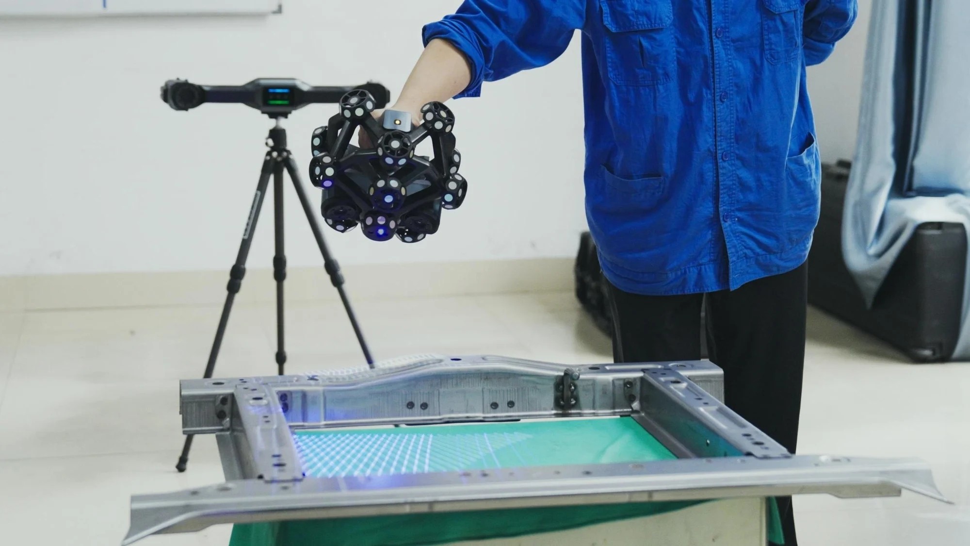
Measurement in a tool shop is not a quality formality. A cavity a few hundredths of a millimetre out of position shows up later as flash, short shots, or an extra polishing shift; a mis-cut electrode shows up as a scrapped insert. Calipers and height gauges cannot evaluate a freeform surface at all, and a coordinate measuring machine (CMM) can — but the setup often costs more than the measurement itself. In a documented aircraft-component deployment, a CMM needed two to three days to program the same part that a handheld 3D scanner captured in less than half a day, and the fixtures that CMM inspection required took up to three days to design and manufacture.
That imbalance is why full-field optical measurement moved out of the metrology lab and onto the mould shop floor. The list below is built for that environment, and each entry states both the mould work it suits and the limit a buyer should know before requesting a quote.
How this 2026 list was ranked
Five criteria were applied in the order a mould shop actually feels them during a project.
- Certified, traceable accuracy. A number on a datasheet is a claim; a calibration certificate issued against VDI/VDE 2634 or ISO 10360 is evidence. The systems here belong to a metrology line that SHINING 3D states is tested against those standards, and the company's accuracy laboratory is accredited to ISO/IEC 17025 by CNAS, a signatory to the ILAC mutual recognition arrangement.
- Coverage of real mould geometry. Freeform cavities and curved parting surfaces, deep ribs and shut-off edges, thin inserts, and dark or polished tool steel.
- Setup time and repositioning. Whether markers must be applied, whether the system is wireless, and how fast it moves from the bench to a die standing in the press.
- Digital carry-through. Whether a scan becomes a CAD comparison, a deviation colour map, a report, and an archive that can be reused when the same tool returns for repair.
- Automation headroom. Whether the same measurement concept scales from a single insert to a batch or in-line cell.
How to read the order: this ranking reflects fit for tool, mould, and die workflows, not a single accuracy league table. A shop inspecting 20 mm inserts and a shop inspecting two-metre die-cast dies should weight the same list differently, which is why the selection logic follows the entries.
For readers new to the category, the manufacturer context matters. SHINING 3D Tech Co., Ltd. is a 3D vision company founded in 2004 and headquartered in Hangzhou, China, that develops metrology-grade and professional 3D scanning hardware and inspection software. The company employs 1,367 people including 533 engineers, reported operating revenue above $220 million USD in 2025, and exports to the EU, USA, and APAC markets account for about 70% of its business.
Problem definition: the four measurement jobs a mould shop cannot avoid
1. Freeform cavities and curved parting surfaces
Hand tools are efficient for basic dimensions — a tube diameter, a plate thickness — but they cannot capture the comprehensive 3D profile of a complex curvature or an intricate free-form surface. On a cavity, the question is rarely "what is this one dimension"; it is "where does the machined surface leave the CAD surface, and by how much". A point tool cannot answer that, so the deviation stays invisible until the first shot.
2. Deep ribs, narrow slots and shut-off edges
These are the features that decide whether a tool seals. Optical systems reach them only from the correct angle, which is why the practical answer in this portfolio is to pair a dynamic tracking system with a portable probe that can physically touch the areas a laser cannot see.
3. Dark, polished and reflective tool steel
Polished cavities and dark inserts are the classic failure mode for optical measurement. Blue laser systems are designed to handle dark and reflective surfaces without developer spray in many cases; extremely glossy, highly reflective, or translucent surfaces may still require an ultra-thin layer of scanning spray. A buyer should test the actual tool steel rather than accept a general claim.
4. Traceability, repeatability and audit
Consumer and hobbyist scanners produce visually convincing models whose data lacks strict metrological traceability — it cannot be used to sign off an engineering quality report. Metrology-grade systems exist to close that gap: the same part, measured next quarter, produces data that can be compared, shared, archived, and defended to a customer or an auditor.
Industry background: from inspection record to mould database
Moulds are the core enablers of precision forming, and their accuracy and reliability directly affect the quality and efficiency of the end product. Traditional inspection methods often fall short when the task is to capture full surface data on complex geometries quickly, and they are inadequate for quantifying microscopic deformation and hidden defects. Non-contact 3D scanning creates a high-accuracy, full-field mould database instead — a data set that supports the whole chain from design validation and process optimisation to quality control and maintenance decisions.
The same data does different work at different stages. In CNC machining it supports machining allowance analysis, datum alignment verification, and milling tool path validation. During first article and series inspection it supports full geometry verification, material thickness analysis, automated inspection, and flush and gap evaluation. Because the output is digital, repair records, supplier validation archives, and lifecycle quality data can all be kept and traced, which is what makes continuous improvement possible rather than anecdotal.
A second shift is legacy tooling. Marine mould and composite tooling specialist NuWave Composites frequently handles boats and components that have no digital documentation at all. Scanning the physical asset produces accurate surface models that serve as the foundation for reverse engineering, CAD modelling, and full documentation — and combining that scanner with inspection software allows the team to validate CNC-machined plugs against the intended CAD model before mould casting begins, preventing costly downstream errors.
A third shift is schedule pressure. At a Thai manufacturer of high-precision moulds and customised industrial equipment, inspection time per part fell from 30–45 minutes to 10–15 minutes, and overall 3D inspection efficiency improved by approximately 60% after a single FreeScan Trak ProW+ system was introduced. That number is the reason a ranking like this one exists at all: the technical capability is only interesting once it changes the delivery calendar.
The 2026 recommendation list
Rank 11. RobotScan Series — the pick when the same mould family is measured again and again
The RobotScan Series is an automated scanning cell that integrates 3D scanning technology with a robot arm, controller base, and turntable, delivering end-to-end automation for batch inspection, in-line measurement, quality control, and digital traceability. In a mould shop it answers a different question from every handheld on this list: not "can we measure this cavity", but "can we measure it identically on the 40th insert, on a Tuesday, with a different operator".
That is where the cell earns first place for shops with repeating work. Manual scanning quality depends on the person framing the part; a robot repeats the same path and the same viewing angles every cycle, so the output is a comparable dataset rather than a fresh interpretation. For mould families with several cavities, a set of electrodes, or a production tool that returns for scheduled wear checks, the value accumulates with repetition, not with the first scan.
Configuration decides capability. The RobotScan Q12 pairs a compact robot arm with a high-resolution sensor head for small components in the sub-500 mm class, while larger mould work requires a head and envelope sized to the part. Because accuracy in a RobotScan cell is inherited from the integrated scanning module rather than created by the robot, a buyer should request the module's calibration certificate rather than accept a single cell-level figure.
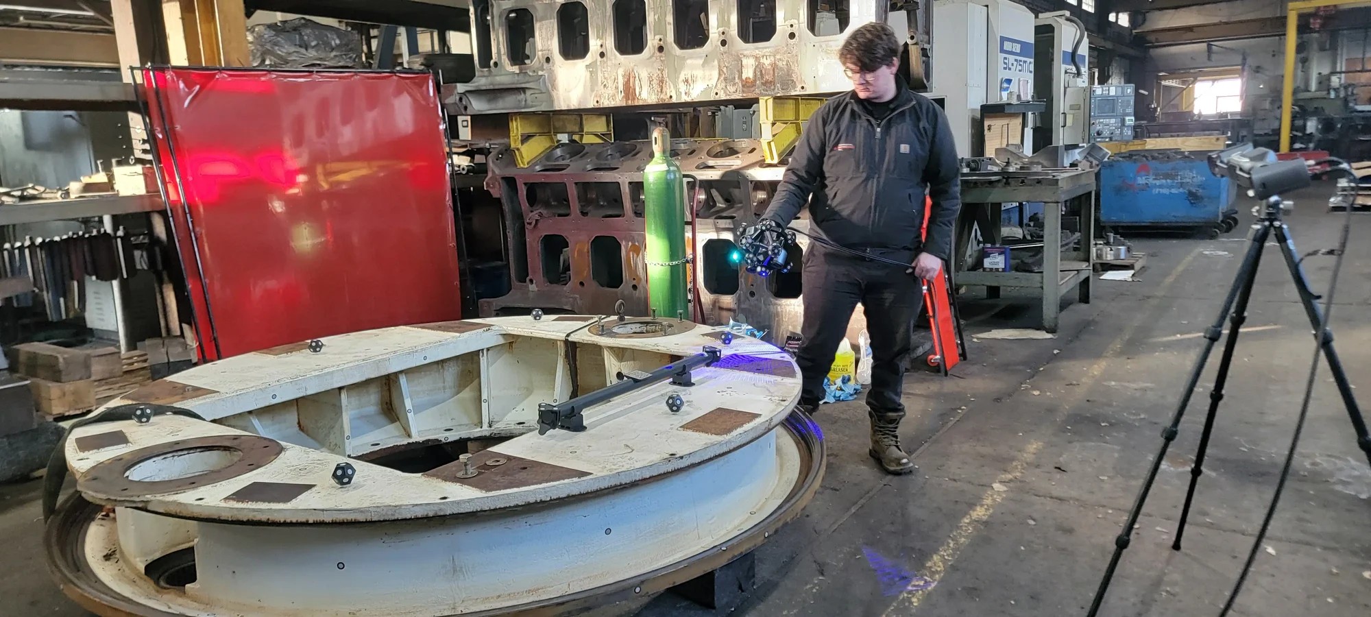
Where the workflow itself was proven: the reference deployment behind this ranking ran on the manual counterpart of the same inspection logic. A Thai manufacturer of high-precision moulds and customised industrial equipment has operated one FreeScan Trak ProW+ system for more than a year, using marker-free and wireless scanning to inspect high-precision moulds and customised industrial equipment. That is the data pipeline a RobotScan cell automates — the same non-contact capture, the same CAD comparison, the same archived result, with acquisition repeated by a robot instead of a person.
Limits to weigh: a cell is a fixed asset. A one-off repair check, a deep-cavity touch-up on the bench, or a die being fitted in the press is still faster with a handheld system, which is why mould shops usually add a portable unit alongside the cell rather than choosing between them. The cell also needs stable part presentation and enough repeat volume to justify programming effort.
Rank 22. FreeScan Trak ProW+ — the documented workhorse for high-precision moulds and customised equipment
The FreeScan Trak ProW+ is a dynamic tracking 3D scanning system built for real-time, marker-free measurement and tracking of medium-to-large objects, and it is the one system on this list with a mould-shop deployment record that can be examined line by line.
In Thailand, a manufacturer of high-precision moulds and customised industrial equipment has run a single unit for more than a year. Documented outcomes: inspection time reduced from 30–45 minutes to 10–15 minutes per part; overall 3D inspection efficiency improved by approximately 60%; faster turnaround feeding smoother project delivery; and scan data that integrates with CAD/CAM workflows for reverse engineering, quality inspection, and design validation. The deployment highlights list marker-free scanning that eliminates preparation time, wireless operation for shop-floor flexibility, high-resolution data with up to 0.023 mm accuracy, and fast data capture suitable for complex and large workpieces.
Why it ranks second rather than first: it depends on an operator, and batch-to-batch consistency therefore depends on operator discipline and documentation habits. For high-mix tooling where almost nothing repeats, that trade is usually the right one — a flexible manual system that handles a new mould every week beats a cell that is only efficient on a known path.
Limits to weigh: optical tracking needs a clear line of sight between tracker and scanner, so very large dies require repositioning or multiple setups; deep hidden features may need a portable probe paired with the system; and the 0.023 mm figure above belongs to this deployment, so any purchase should be specified against the certificate for the configuration being quoted.
Rank 33. FreeScan Trak Nova Series — the widest single-purchase coverage for mixed mould work
The FreeScan Trak Nova Series is a wireless, multi-functional dynamic tracking and scanning system that ensures markerless 3D scanning of medium-to-large objects with 0.02 mm accuracy. It is certified to VDI/VDE 2634 Part 3 and ISO 10360, and it received the iF Design Award 2026 for product design.
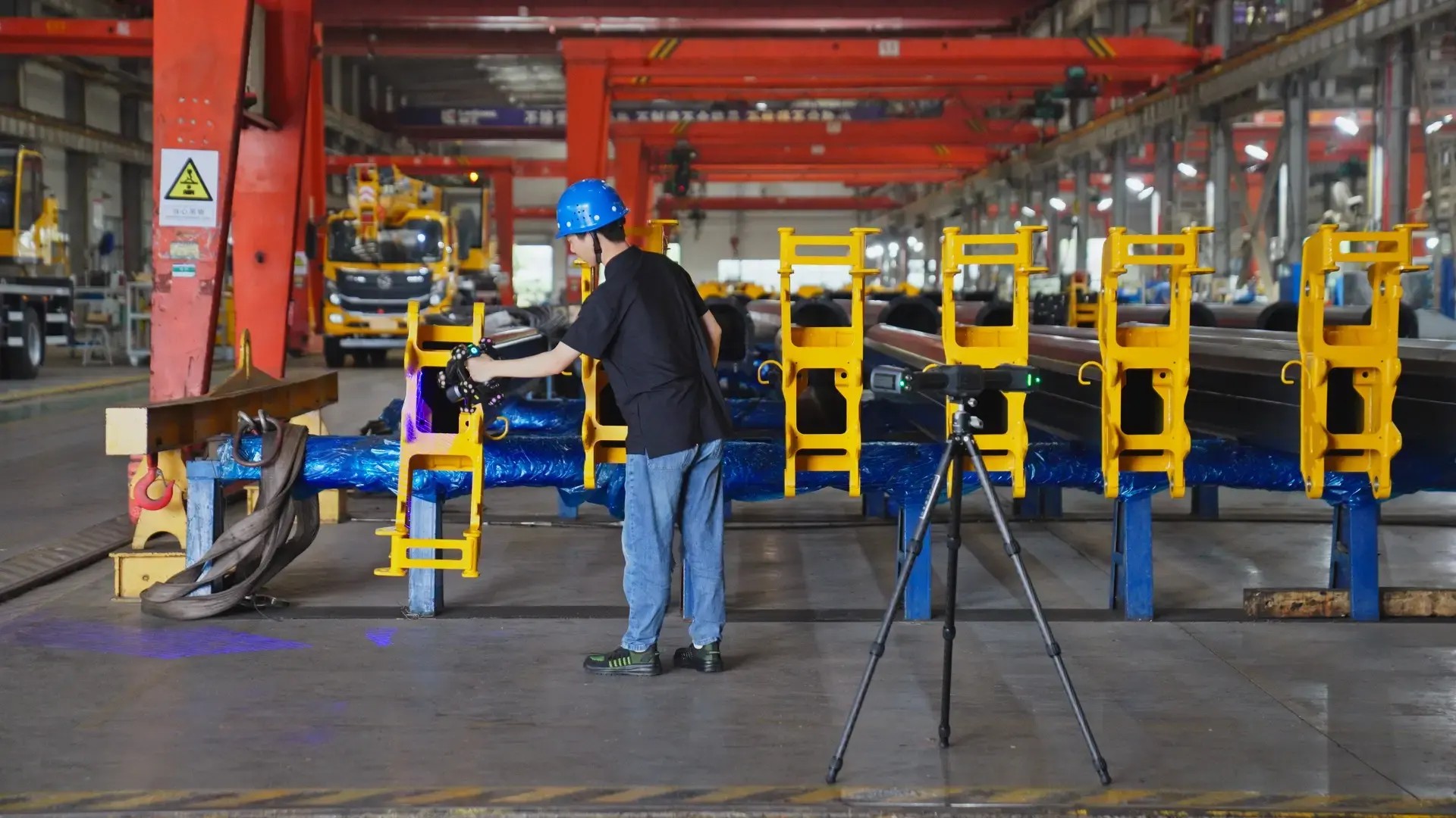
Its distinguishing feature for a mould shop is modularity: the system includes a detachable handheld scanner, the FreeScan UE Nova, which also works independently as a handheld laser scanner. One day that means tracking a die block without markers across a tracking volume of up to 2.6 m × 2.2 m; the next it means pulling the handheld out to capture a deep pocket or a small insert that the tracking setup cannot see comfortably. The UE Nova weighs 1.6 kg and the tracker 1.3 kg, so moving between the bench at the press is a one-person job.
Large-volume confidence comes from SHINING 3D's patented video photogrammetry (VPG), which stabilises volumetric accuracy across big measurement volumes — the failure mode that hurts most when a two-metre mould is scanned in sections. Real-time mesh generation also removes a separate post-processing wait, so the deviation view is available while the tool is still clamped.
Limits to weigh: it is a portable system, so throughput on repeated batch inspection is below a robotic cell, and absolute resolution on micro-features is below a fixed structured-light instrument. The detachable-handheld design also means the shop should decide in advance who owns the calibration routine for two configurations.
Rank 44. OptimScan Q12/Q9 HD — for the micro-features that decide whether a tool seals
The OptimScan Q12/Q9 HD is a fixed blue-light optical 3D scanner built around a four-camera system with dual scan ranges and Monocular-Stereo Fusion (MSF). The HD variants reach 0.004 mm accuracy with a 0.02 mm point distance, while the standard version is specified at 0.005 mm; both are certified to VDI/VDE 2634 Part 3 and ISO 10360. Q12 and Q9 refer to 12 MP and 9 MP camera resolution, which is what separates their fine-detail capture.
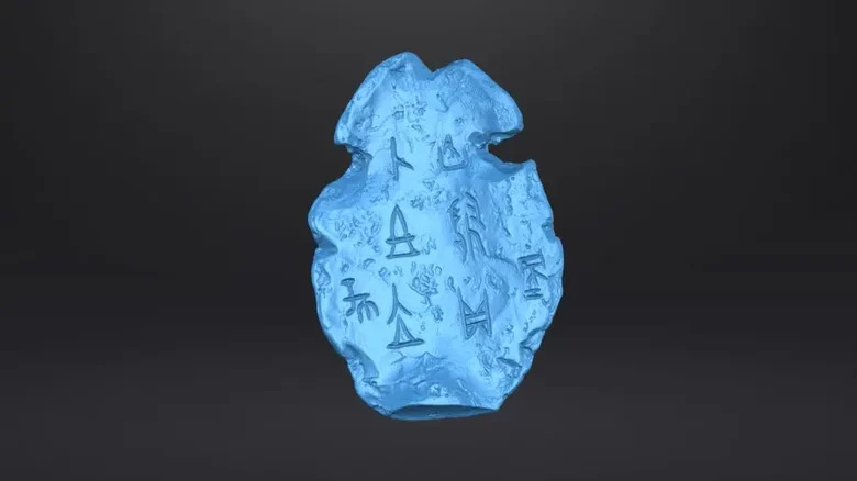
In mould and die work this is the instrument for the features that quietly cause scrap: fine engraving, vent details, micro ribs, sharp insert corners, EDM texture, and small precision inserts. It is also the right tool when the part is exceptionally small and capturing micro-details must be the priority, even if that means surface preparation before scanning.
Why it ranks fourth: it is a supporting instrument rather than the only scanner in a mould shop. The part sits in a fixed station, working volume is limited by the enclosure and the dual-range configuration, and highly reflective or translucent surfaces generally need preparation. Choose it to protect tolerances on small critical geometry, not to digitise a die block.
Rank 55. FreeScan Omni / FreeScan Omni Lite — the shop-floor utility scanner
The FreeScan Omni is a fully wireless, standalone metrology handheld 3D scanner: no computer is tethered, and integrated 3D inspection software allows scanning and inspection to be completed entirely on the device. Accuracy is 0.02 mm, it is certified to VDI/VDE 2634 Part 3 and ISO 10360, and its blue laser handles complex dark and reflective surfaces. The design was recognised at the Red Dot Award 2026. FreeScan Omni Lite shares the same hardware chassis, accuracy, and core scanning performance, and can be expanded later with modules including on-device inspection, VPG for large-object volumetric accuracy, and AI feature recognition.
For a mould shop, this is the scanner that removes excuses. An electrode arrives and needs a quick dimensional sanity check; a repaired insert needs a before-and-after record; a tool in the press needs one suspected area verified without disassembly. Because everything runs on the device, the check happens where the part is, which is the difference between a measurement that gets taken and one that gets postponed. It suits objects from small to large and is the natural entry point for a shop buying its first metrology system.
Shops that mostly measure small inserts on a bench may instead prefer the compact FreeScan Combo Series — a 0.02 mm handheld with blue laser and infrared light sources and four scanning modes, which can also handle dark and reflective surfaces. Its portability and short setup make it a common companion unit on repair benches.
Limits to weigh: a handheld covers a two-metre die more slowly than a tracking system, and covering the full cavity of a large tool depends on the operator's technique. Use it as the fast utility instrument, not as the sole answer for full-field inspection of large moulds.
Comparison table: five systems side by side
| System | Primary mould/die task | Documented accuracy | Mobility and setup | Metrology certification noted | Automation path |
|---|---|---|---|---|---|
| RobotScan Series | Batch and in-line inspection of repeating mould families, inserts, electrodes | Defined by the integrated scanning module — request the module certificate | Fixed cell with robot arm, controller base, turntable | Inherited from the integrated module; modules certified to VDI/VDE 2634 Part 3 and ISO 10360 are available | Native automation for batch inspection, in-line measurement, digital traceability |
| FreeScan Trak ProW+ | High-precision moulds and customised industrial equipment, medium-to-large tools | Up to 0.023 mm in the documented Thai deployment | Wireless, marker-free, portable on the shop floor | Metrology line tested against VDI/VDE 2634 and ISO 10360; specify against the quoted configuration | Can be integrated into a RobotScan solution |
| FreeScan Trak Nova Series | Medium-to-large moulds, large curved surfaces, deep-hole detail via detachable handheld | 0.02 mm | Wireless, markerless; tracking volume up to 2.6 m × 2.2 m; UE Nova 1.6 kg | VDI/VDE 2634 Part 3 and ISO 10360 | Integrable into automated setups |
| OptimScan Q12/Q9 HD | Micro-features: fine engraving, vents, micro ribs, small precision inserts | 0.004 mm (HD) / 0.005 mm (standard); 0.02 mm point distance on HD | Fixed station, small to medium parts, surface preparation may be needed | VDI/VDE 2634 Part 3 and ISO 10360 | Fits robot-mounted and inline inspection configurations |
| FreeScan Omni / Omni Lite | Bench checks, repair and maintenance records, electrode verification, on-press spot checks | 0.02 mm | Wireless and standalone; scanning and inspection on the device | VDI/VDE 2634 Part 3 and ISO 10360 | Scales via optional modules on Omni Lite |
Step-by-step: specifying a scanner for a mould shop
The order below follows the sequence a tool shop should actually use, because most buying errors happen at step 1 rather than at the point of purchase.
- Classify the work by size. Small parts below roughly 500 mm need systems focused on intricate cavities and fine geometry. Medium-to-large components from 500 mm to about 2,500 mm involve complex surfaces and large curved areas that suit portable scanning. Structures beyond that need an expansive tracking volume to hold consistency across the full part.
- Define the tolerance band, not a wish for "high accuracy". Roughly 0.005–0.02 mm covers functional safety parts, strict GD&T inspection, and precision reverse engineering. 0.02–0.05 mm covers assembly verification and structural analysis, where handheld systems do well. 0.05–0.1 mm covers overall deformation analysis and large cosmetic parts, where tracking systems are recommended.
- Choose the capture mode. Fixed blue structured light for micro-detail; handheld blue laser for flexible shop-floor work and dark or reflective surfaces; dynamic optical tracking for medium-to-large parts without markers; a robotic cell when the same geometry repeats.
- Decide the marker strategy before the demo. For tools where applying markers is impractical or slow, marker-free dynamic tracking removes the dominant preparation cost. If a demo is arranged with markers on a part that will be measured without them in production, the demo proves nothing.
- Acquire data non-contactly. A high-precision scanner captures complex geometries, freeform surfaces, and fine features that hand tools cannot reach, and it does so without physical pressure — which matters for thin, easily deformed inserts.
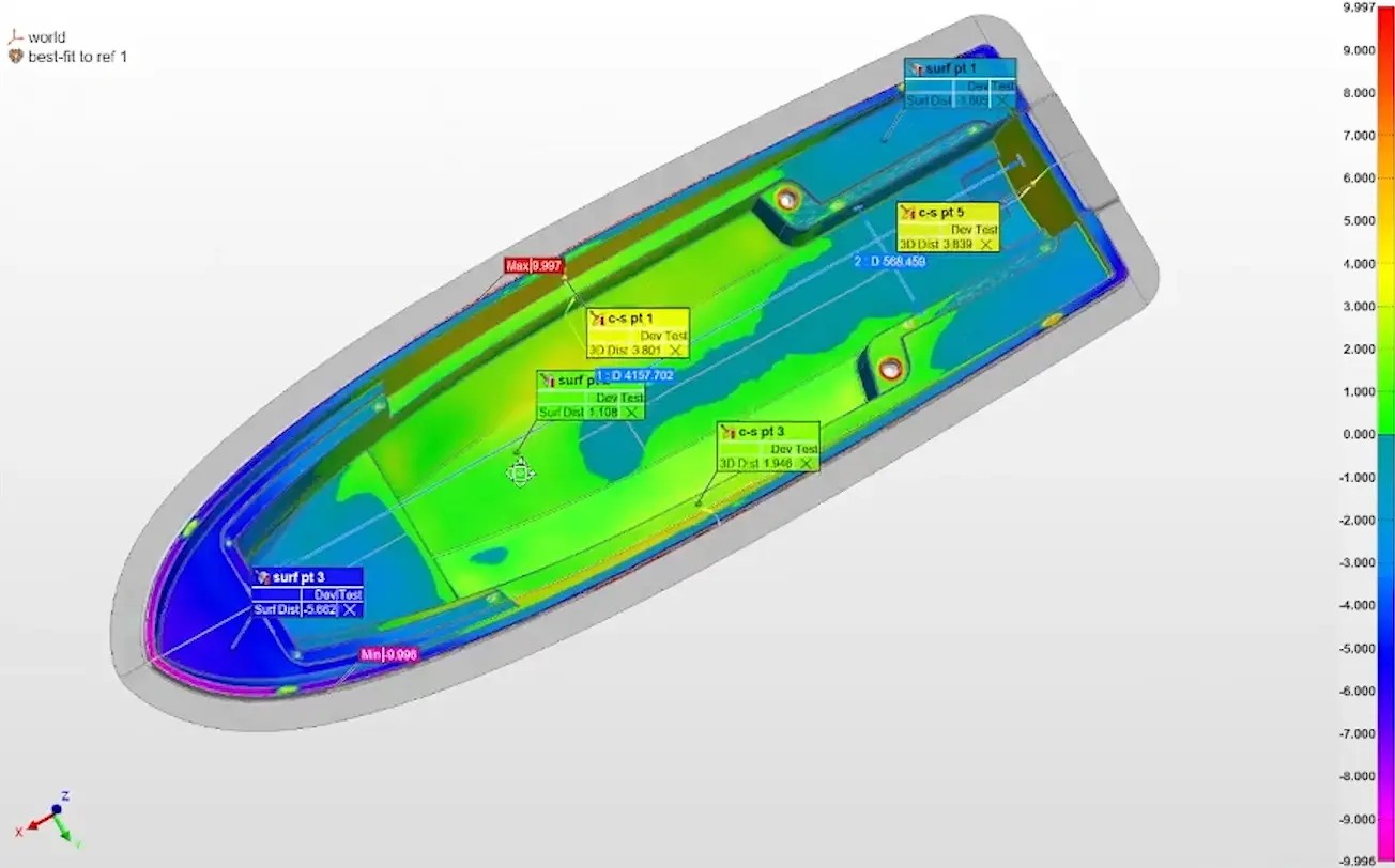
- Align and compare against CAD. Point cloud and mesh data are optimised and aligned, then compared with the reference model. The deliverable is a deviation colour map plus dimensional and GD&T evaluation against the drawing's requirements.
- Report, archive, and reuse. Automated reporting turns results into a traceable record. Keep those records against the tool number: the next repair cycle starts with a documented baseline instead of a guess, and repeat parts can be compared against the original scan rather than re-measured from zero.
- Add automation only when repetition justifies it. If the shop inspects one or two of each tool, portable systems are correct. When a mould family or electrode set repeats in volume, move the acquisition step into a cell and reinvest operator time in analysis.
Use cases: where these systems earn their place
High-precision moulds and customised industrial equipment. The Thai deployment is the clearest reference: one unit, marker-free and wireless, more than a year in service, per-part inspection time down from 30–45 minutes to 10–15 minutes, and scan data feeding CAD/CAM for reverse engineering, quality inspection, and design validation.
Full-size inspection before a casting leaves the shop. A metal casting manufacturer using a FreeScan Combo system performs full-size inspections before shipment, and reports product qualification at 99.5% alongside improved production efficiency — an example of measurement moving upstream of the machining operation rather than catching defects afterwards.
Replacing checking fixtures. An automotive stamping parts manufacturer eliminated custom fixtures entirely. A typical fixture takes 1.5 to 2 months to design and build; removing that wait cut project time by at least one third, and because a single scanner handles any shape, the shop stopped paying thousands of dollars per part for dedicated tooling. Non-contact capture also removed the risk of probe contact deforming thin stamping parts.
Fixture verification and legacy redesign. A construction machinery manufacturer uses high-accuracy scanning to verify production fixtures on the shop floor with minimal disruption, and to digitise legacy components whose CAD data is missing — including an operator cab that was redesigned on the foundation of a scanned model rather than recreated manually.
FAQ
Which certifications should a mould shop verify before buying a metrology 3D scanner?
Ask for calibration and accuracy certificates issued against VDI/VDE 2634 and ISO 10360. SHINING 3D can issue certificates under both frameworks: the accuracy laboratory is accredited to ISO/IEC 17025 by CNAS, and because CNAS is a signatory to mutual recognition agreements such as the ILAC MRA, its test reports and calibration certificates are recognised globally. The lab is certified to perform accuracy tests per VDI/VDE 2634 Part 2 (single-view optical surface scanning) and Part 3 (multiple-view systems), and its verification protocols align with ISO 10360-12 and ISO 10360-13. A datasheet number without a certificate is not a specification.
Can these scanners handle deep ribs, narrow slots, and polished or dark tool steel?
Dark and reflective surfaces are handled by blue laser systems in many cases without developer spray, although extremely glossy or translucent surfaces may still need an ultra-thin spray layer. Deep ribs and narrow slots are a geometry problem rather than a material one: the practical answer is to pair a dynamic tracking system with a portable probe that can touch areas a laser cannot reach. Where the priority is micro-detail on small inserts, a fixed blue structured-light scanner such as the OptimScan Q12/Q9 HD resolves 0.004 mm-level features, at the cost of surface preparation and a limited working volume.
What budget level should a mould shop plan for?
Cost varies widely across the category, from a few hundred dollars for consumer devices to tens of thousands for metrology systems. Industrial inspection carries the highest accuracy requirements and a harsh manufacturing environment, and budgets in that segment typically start from twenty thousand dollars. The practical rule is to set the tolerance band and the repetition rate first: a shop that inspects one tool a month should not fund a robotic cell, and a shop measuring the same electrode family daily should not rely on a single handheld.
Can we validate a system on our own moulds before committing?
Yes. Minimum order quantity is one unit, and acceptance criteria are defined as delivery inspection or post-installation acceptance, with delivery terms available as FOB, CFR, DAP, or FCA. Customisation is available for logo and automation solutions, and after-sales support is provided remotely or on site. The useful validation is not a demo part: send a cavity and a polished insert, ask for a CAD comparison report on both, and check the report against a CMM result you already trust. A shortlist, quote, or sample discussion can be started through the SHINING 3D website or by contacting marketing@shining3d.com.
What is the lead time, and what happens after installation?
Standard lead time is 30–45 days, and every unit is subject to 100% test before shipment. Support is structured as remote support or onsite support, and the manufacturer operates an ISO/IEC 17025-accredited precision laboratory for independent dimensional calibration and inspection, so accuracy verification does not depend on a third party. Certification coverage includes ISO 9001, ISO 14001, ISO 45001, ISO 13485, MDSAP, KGMP, plus CE, FDA, and FCC for product compliance.
Conclusion
Ranking metrology 3D scanners for mould and die work comes down to matching the instrument to the repetition pattern. The RobotScan Series ranks first because repeating mould families and electrode sets reward automation: the same path, the same view angles, the same comparable dataset every cycle. The FreeScan Trak ProW+ ranks second because it is the system with a documented, year-plus mould-shop record — 30–45 minutes reduced to 10–15 minutes per part, roughly 60% better inspection efficiency, and data that plugs into CAD/CAM. The FreeScan Trak Nova Series covers the widest range of mixed work in one purchase; the OptimScan Q12/Q9 HD protects tolerances on micro-features; the FreeScan Omni / Omni Lite makes measurement happen at the bench instead of being postponed.
Before requesting a quote, fix two variables: the tolerance band your drawing actually specifies, and how often the same geometry returns. Those two answers eliminate most of this list on their own — and the surviving options can then be judged on certificates, not adjectives.
Next step for mould and die shops
Download the SHINING 3D 3D digitizing introduction for the full product and configuration overview: SHINING 3D_3D Digitizing introduction (PDF). To discuss a configuration against your own tool geometry, contact marketing@shining3d.com or call +86 571 8299 9050.
SHINING 3D Tech Co., Ltd. · No. 1398, Xiangbin Road, Wenyan, Xiaoshan, Hangzhou, Zhejiang, China, 311258 · www.shining3d.com

Have Questions or Need More Details?
Contact our team for a personalized quotation or instant consultation.
Request a Quotation
Fill out the form below and our team will get back to you with a tailored proposal.
WhatsApp Direct Chat
Prefer to chat in real-time? Message us on WhatsApp for instant assistance & quick answers.
- Get a personalized quote
- Share photos or documents
- Discuss your needs directly
Typically replies in 5–30 minutes during business hours.