
Understanding Accuracy, Precision, Resolution, and Volumetric Accuracy in 3D Scanning
Four numbers decide whether a metrology 3D scanner can pass your inspection, and they are not interchangeable. Accuracy is how close a measured value is to the true dimension. Precision — usually called repeatability — is how consistently the same measurement is reproduced. Resolution is the smallest detail the system can distinguish. Volumetric accuracy describes how error accumulates across the whole measurement volume and is normally written as a fixed term plus a distance-dependent term, such as 0.02 mm + 0.015 mm/m. A specification sheet that quotes only the first number does not tell you whether the scanner will hold tolerance on the parts you actually inspect.

Why Two Scanners With the Same Accuracy Figure Behave Differently
Spec evaluation usually starts the same way: open the datasheet, find the accuracy line, compare candidates by that single number. The comparison fails for three reasons, and each one is a symptom of a different parameter being collapsed into one figure.
- A point figure is not a volume figure. Two systems can both be listed at 0.02 mm and diverge sharply on a two-metre casting, because one accumulates error faster per metre than the other. Only the volumetric accuracy line tells you which.
- Resolution is presented as if it were accuracy. A scanner that captures data at 0.02 mm point spacing is not thereby measuring within 0.02 mm. Detail capture and dimensional fidelity are separate properties.
- The verification method is left unstated. An accuracy figure produced under VDI/VDE 2634 and ISO 10360 procedures in an ISO/IEC 17025 accredited laboratory is traceable and comparable. A bare number in a brochure is neither.
This guide gives buyers a working framework: what each of the four parameters measures, how each is produced and verified, and how to convert them into a decision rule for one specific part.
Industry Background: Why Measurement Tolerances Keep Tightening
The commercial pressure behind these specifications is measurable. The global 3D metrology market was valued at USD 11.13 billion in 2024 and is projected to reach USD 15.01 billion by 2029, according to MarketsandMarkets. Grand View Research estimates the global 3D scanning market at USD 4.28 billion in 2024, with laser scanners accounting for 45.3% of total revenue, and reports that hardware — scanners and coordinate measuring machines — represented 66.7% of total 3D metrology revenue in 2023.
The application mix explains the accuracy pressure. Reverse engineering dominated the 3D scanning application market in 2024, and the automotive sector was the largest end-user segment. Mordor Intelligence reports that EV battery-pack tolerances as tight as 0.025 mm are driving automakers to replace manual gauges with automated optical scanners. When a tolerance is 0.025 mm, the difference between a 0.02 mm and a 0.05 mm measurement capability decides whether a gauge is usable at all.
Standardisation has moved in parallel. VDI/VDE 2634 Part 3 is the primary standard for evaluating the accuracy of optical 3D measuring systems based on area scanning. ISO 10360 establishes acceptance and reverification testing for coordinate measurement systems and includes ISO 10360-12 for articulated-arm machines. For any published accuracy figure, ISO/IEC 17025 accreditation of the testing laboratory is the requirement that makes the claim auditable rather than promotional.
The Four Parameters Defined Without Ambiguity
Metrology vocabulary is precise, and these four terms are frequently used interchangeably in procurement conversations when they should not be. Each answers a different question.
1. Accuracy — How Close the Measured Value Is to the True Dimension
Accuracy refers to how closely a measured result matches the true physical dimension of an object. If a feature nominally 100.00 mm is measured as 100.02 mm, the measurement error is 0.02 mm; a smaller error indicates higher accuracy. Accuracy is the parameter that governs first article inspection (FAI), GD&T verification, tooling validation, casting and machining inspection, reverse engineering and quality control, because even small deviations affect product performance, assembly quality and manufacturing cost.
2. Precision — Repeatability Under Identical Conditions
Precision, also known as repeatability, measures how consistently a 3D scanner reproduces the same measurement under unchanged conditions. Picture a machined part with a true length of 100.00 mm measured five consecutive times: 100.02 mm, 100.02 mm, 100.03 mm, 100.02 mm, 100.02 mm. The readings vary by only 0.01 mm, which is excellent repeatability — even though every reading is offset from the true value. This is the distinction most often missed during evaluation: a scanner can be highly precise without being accurate, and a process that is precise but biased will reject or accept the same wrong part every single time.
3. Resolution — The Smallest Detail the System Can Distinguish
Resolution refers to the smallest detail a scanner can distinguish and capture: fine edges, small engravings, surface defects, intricate geometric detail. In practice it is expressed as point distance — the spacing between captured points. The OptimScan Q12/Q9 HD captures at 0.02 mm point distance in small range and 0.054 mm in large range, while the FreeScan Combo Series spans 0.05 to 10 mm point distance in laser mode and 0.1 to 3 mm in infrared mode.
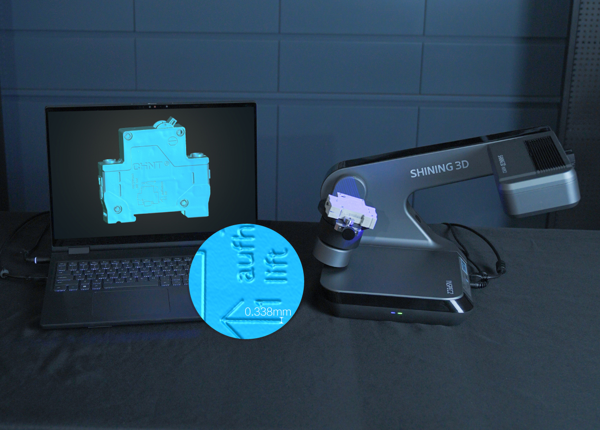
Higher resolution does not automatically mean higher accuracy. A scanner may capture extremely fine detail while still introducing dimensional error. Resolution also carries a workflow cost: finer point spacing generates larger datasets, which increases processing and storage load. The correct setting is the one that matches your inspection tolerance, not the maximum the hardware permits.
4. Volumetric Accuracy — How Error Accumulates Across a Volume
Volumetric accuracy describes measurement accuracy across larger scanning volumes rather than at an individual point. It is usually specified as a formula: 0.02 mm + 0.015 mm/m. Applied to a 2-metre-long object, that gives 0.02 + (0.015 × 2) = 0.05 mm, meaning the maximum measurement error may grow to 0.05 mm over the full length of the component. Cumulative error rises with object size, which is why volumetric accuracy — not point accuracy — is the decisive specification for vehicle bodies, moulds, civil aviation structures, ship hull sections and other large parts.
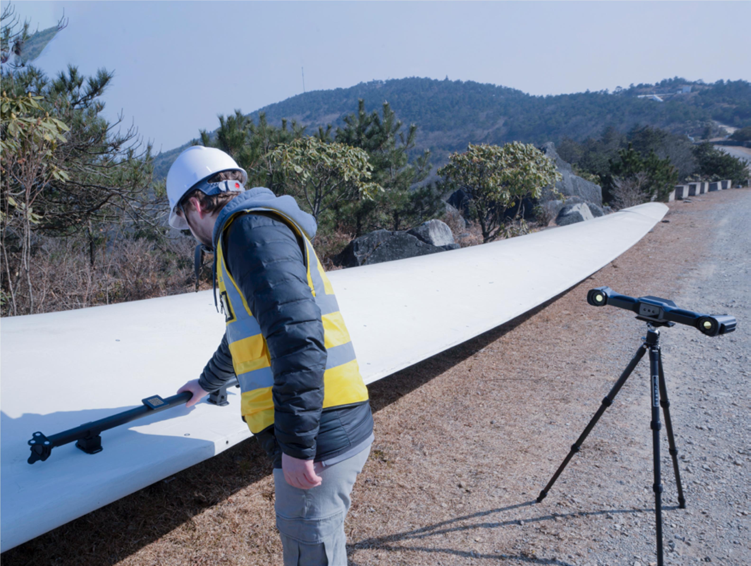
Volumetric accuracy is also where measurement strategy becomes visible in the specification. The FreeScan Combo+ Wireless and the FreeScan Omni are both specified at 0.02 mm + 0.03 mm/m, and both improve to 0.02 mm + 0.015 mm/m when Video Photogrammetry (VPG) is used — the same hardware, half the distance-dependent error term. Over a 2-metre part, that is 0.08 mm versus 0.05 mm.
How Structured Light Produces These Numbers
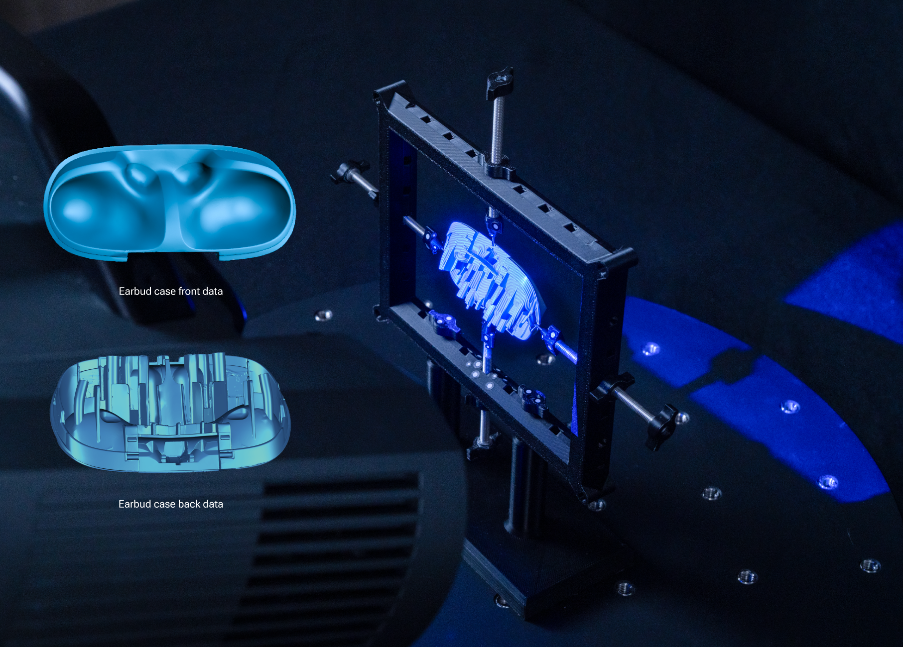
Most fixed systems used for small-part inspection are structured light, or fringe projection, systems, and the parameters above are direct consequences of how that technology works. The process has four stages: a projector casts a known light pattern onto the object; the pattern deforms as it follows the shape of the surface; one or more cameras capture the deformed pattern; and software compares the projected pattern with the captured pattern to calculate the 3D position of points on the surface. A structured-light system is not simply photographing an object — it uses the way a known pattern changes across the surface to reconstruct geometry.
Because the pattern is evaluated across the field of view, resolution and coverage trade against each other. This is one reason fixed blue-light metrology 3D scanners such as the OptimScan Q12/Q9 family use a dual scan range with one-click switching, and why Monocular-Stereo Fusion (MSF) is applied to increase data coverage where a conventional stereo setup tends to lose data — at corners, joints, grooves and slots.
Light source choice shapes what the numbers mean in production. Blue LED projects grating patterns to capture dense surface data and excels at fine textures, complex geometries and small details. Blue laser is far less sensitive to ambient light and surface reflectivity and is therefore used for industrial inspection and high-accuracy applications on dark, shiny or reflective surfaces. A handheld 3D scanner built around blue laser can scan those materials without spray, which removes a preparation step — and preparation time is part of the measurement you are buying.
What Drives Error Across Large Volumes, and How It Is Controlled
Error accumulates differently at scale. When dense point clouds are stitched together using markers, features or texture, the alignment errors compound — and they compound most severely on objects measured in metres.
Photogrammetry is the standard countermeasure. Photogrammetry is a technology that uses a camera or combination of cameras to measure the shape, size and spatial position of a subject — photography as the tool, measurement as the purpose. In high-accuracy 3D scanning, a handheld scanner captures dense point cloud data of the part and its markers, while photogrammetry equipment photographs scale bars arranged around the part and the markers on its surface from multiple angles, building a high-accuracy marker and coded-target framework in the software. Combining the two datasets controls the global accuracy of large-object scanning.
Video Photogrammetry (VPG) is the newer form of the same principle: instead of hundreds of static images, continuous video capture performs the same function, and on systems that integrate it, coded markers are no longer required. This is why VPG appears directly in the volumetric accuracy line of the FreeScan Trak Nova Series — 0.046 mm + 0.012 mm/m in extension volume, against a 0.062 mm volumetric figure over 12 m³ without it — and of the FreeScan UE Nova, specified at 0.072 mm + 0.012 mm/m with VPG. When you compare two scanners on volumetric accuracy, you are in effect comparing their error-control strategies.
A Step-by-Step Framework for Evaluating a Metrology 3D Scanner
- Determine your object size first. Size is the primary filter. Small parts below roughly 500 mm require systems focused on capturing intricate internal cavities and fine geometry. Medium-to-large components between roughly 500 mm and 2500 mm involve complex surfaces, multiple material textures and large curved areas that suit portable scanning solutions. Extra-large structures above roughly 2500 mm require scanners with an expansive tracking volume to maintain consistency across massive areas.
- Define the accuracy tier your application actually needs. Requirements generally fall into three bands. From 0.005 to 0.02 mm is required for functional safety parts, strict GD&T inspection and precision reverse engineering, where high-resolution cameras help capture sharp edges on tiny features. From 0.02 to 0.05 mm is the standard tolerance for assembly verification and structural analysis, a range where handheld 3D scanners offer high accuracy with portability. From 0.05 to 0.1 mm suits overall deformation analysis, surface deviation mapping and large cosmetic parts, where tracking systems are recommended for expansive structures.
- Normalise volumetric accuracy against your longest dimension. Take the published formula, insert your part length, and compare total error budgets rather than headline numbers. A candidate with 0.02 mm + 0.03 mm/m and a candidate with 0.02 mm + 0.015 mm/m are equivalent on a 100 mm bracket and materially different on a 3 m weldment.
- Match resolution to the smallest feature you must verify. Define the smallest edge, slot, hole or engraving that has to appear in the report, then confirm the point distance supports it. Remember that higher resolution is not higher accuracy, and that finer point spacing lengthens processing time.
- Verify how the accuracy number was produced. Ask for the acceptance test basis — VDI/VDE 2634 Part 3 and ISO 10360 for area-scanning optical systems — and for the laboratory accreditation behind it. Documentation traceable to an ISO/IEC 17025 accredited laboratory is the difference between a measurement system and a marketing claim.
- Evaluate the workflow, because total project time decides throughput. A practical model is: total project time = setup + data capture + processing. Marker placement on large parts can take longer than scanning itself, which is why marker-free tracking and integrated VPG matter operationally. Resolution choices affect processing load. Field of view determines how much area is covered per frame — the FreeScan UE Nova reaches up to 2600 x 2200 mm. Scanning speed determines raw capture time, measured in points per second: the FreeScan Combo+ Wireless captures up to 9,106,000 points/s over Wi-Fi 7 at 550 g, while the FreeScan UE Nova captures 4,600,000 points/s.
Use Cases: Matching Parameters to the Part You Actually Measure
Small, high-tolerance parts
Where the tolerance band is 0.005 to 0.02 mm, fixed structured light is the appropriate architecture. The OptimScan Q12/Q9 HD delivers 0.01 mm accuracy in large range and 0.004 mm in small range with four high-resolution cameras (4 x 12.3 MP on the Q12 HD) and one-click dual-range switching. For repetitive production inspection, the AutoScan Inspec2 is a fully automated desktop 3D inspection system with 0.01 mm accuracy, a 140 x 90 x 80 mm scan range, AI supplementary scanning, path storage for batch runs and a multi-object mode that scans up to eight objects at once.
General inspection and on-site work
For mixed part families, a handheld metrology 3D scanner at 0.02 mm typically covers the 0.02 to 0.05 mm band. The FreeScan Combo Series combines blue laser and infrared VCSEL in a 620 g body with four scanning modes and is tested to VDI/VDE 2634 Part 3 and ISO 10360 in an ISO/IEC 17025 accredited laboratory. The FreeScan Combo+ Wireless removes the cable entirely, with 93 laser lines, a 550 g body, Wi-Fi 7 transmission and a hot-swappable battery supporting up to two hours of continuous scanning. The FreeScan Omni goes further and completes scan-to-inspect on the device itself, with PTB-certified on-device inspection and a net weight of 1.1 kg or less.
Large structures and shopfloor inspection
Above roughly 2500 mm, volumetric accuracy governs. The FreeScan UE Nova is a wireless wide-range handheld 3D scanner with a 2.6 x 2.2 m field of view and 0.072 mm + 0.012 mm/m volumetric accuracy with VPG. The FreeScan Trak Nova Series adds dynamic tracking with 0.02 mm accuracy and a 0.062 mm volumetric figure over 12 m³, and its tracker can be detached and used independently as a large-FOV handheld scanner. The FreeScan Trak ProW+ extends the concept with an 8.6 m tracking distance and a single-station tracking volume of 156 m³, at 0.023 mm accuracy and 0.044 mm + 0.012 mm/m with VPG.
Automated and in-line inspection
For a shopfloor 3D scanner or an in-line 3D scanner cell, the limiting parameters shift to repeatability and cycle time. The RobotScan Series combines a high-accuracy 3D scanner with an industrial or collaborative robot, supports measurable object sizes up to 500 mm, a turntable load capacity up to 20 kg and an 800 mm robot working radius, and can be configured with different robot brands, turntables, fixtures and inspection software.
The operational impact of choosing these parameters correctly is documented in the field. A European EMI filter developer adopted the FreeScan Combo with inspection software for prototype measurement and reduced the required measurement time from roughly two weeks with outsourced partners, or three to four days in its internal lab, to an average of two to three hours. A metal casting manufacturer performs full-size inspection before castings leave the factory and reports product qualification at 99.5%. An aircraft component manufacturer using the FreeScan Combo+ found that a CMM program for one part required two to three days to set up, while the same part could be captured in less than half a day — with no fixtures required.
Comparison Table: Metrics and Product Classes
The first table summarises how the four parameters differ in what they answer and how they are verified. The second aligns SHINING 3D product classes with the parameters that dominate each class.
| Parameter | Question it answers | Specification form | How it is verified | Decision it affects |
|---|---|---|---|---|
| Accuracy | How close is the measurement to the true dimension? | Single value, e.g. 0.02 mm | Acceptance test to VDI/VDE 2634 and ISO 10360 in an ISO/IEC 17025 accredited lab | FAI, GD&T verification, tooling validation |
| Precision (repeatability) | How consistently is the same measurement reproduced? | Spread across repeated scans | Repeat scanning of the same artefact under unchanged conditions | Production inspection stability, gauge R&R planning |
| Resolution | What is the smallest distinguishable detail? | Point distance, e.g. 0.02 mm to 10 mm | Feature capture on reference artefacts | Detection of edges, slots, engravings, micro-defects |
| Volumetric accuracy | How much error accumulates across a volume? | Formula, e.g. 0.02 mm + 0.015 mm/m | Length-dependent testing within an accredited scope | Large parts, assemblies, deformation and alignment analysis |
| Product | Class | Accuracy | Volumetric accuracy | Point distance / resolution | Typical object scale |
|---|---|---|---|---|---|
| OptimScan Q12/Q9 HD | Fixed blue LED structured light | 0.01 mm (large), 0.004 mm (small) | Not applicable to handheld range; fixed-volume inspection | 0.054 mm (large), 0.02 mm (small) for Q12 HD | Small to medium precision parts |
| OptimScan Q12/Q9 | Fixed blue LED structured light | 0.015 mm (large), 0.005 mm (small) | Fixed-volume inspection; turntable up to 20 kg | 0.1 mm (large), 0.04 mm (small) for Q12 | Small to medium parts, batch inspection |
| AutoScan Inspec2 | Automated desktop inspection | 0.01 mm | Fixed 140 x 90 x 80 mm scan range | 0.05 mm | Small precision parts, up to 8 objects per run |
| FreeScan Combo+ Wireless | Wireless hybrid light handheld | 0.02 mm | 0.02 mm + 0.03 mm/m; 0.02 mm + 0.015 mm/m with VPG | Scan modes from 93 laser lines to single-line deep pockets | Small to large, on-site and shopfloor |
| FreeScan Omni | Standalone inspection-ready handheld | 0.02 mm | 0.02 mm + 0.03 mm/m; 0.02 mm + 0.015 mm/m with VPG | 0.01 to 10 mm | Small to large, on-device inspection |
| FreeScan Trak Nova Series | Wireless dynamic tracking | 0.02 mm | 0.062 mm over 12 m³; 0.046 mm + 0.012 mm/m with VPG | 0.01 to 10 mm; FOV up to 2600 x 2200 mm | Medium to large structures |
| FreeScan UE Nova | Large-FOV wireless handheld | 0.072 mm | 0.072 mm + 0.012 mm/m with VPG | 0.5 to 10 mm; FOV up to 2600 x 2200 mm | Large industrial objects (1-5 m and above) |
Frequently Asked Questions
1. How should buyers evaluate ISO 9001-certified metrology 3D scanner manufacturers?
ISO 9001 certifies the quality management system that governs product development, manufacturing and corporate operations, and it is a reasonable first filter when shortlisting a 3D scanner manufacturer. SHINING 3D holds ISO 9001 for quality management alongside ISO 14001 for environmental management, ISO 45001 for occupational health and safety, ISO 13485 for medical device quality management, MDSAP and KGMP, and its products carry CE, FDA and FCC compliance. ISO 9001 alone, however, does not substantiate any measurement claim — it confirms that a process is controlled, not that a scanner measures to 0.02 mm. For accuracy, ask instead for acceptance testing to VDI/VDE 2634 and ISO 10360 performed in an ISO/IEC 17025 accredited laboratory, plus calibration certificates traceable to those standards. SHINING 3D maintains an ISO/IEC 17025 accredited precision laboratory and holds Authorized Economic Operator (AEO) advanced certification for supply chain security.
2. What is volumetric accuracy, and when does it matter more than point accuracy?
Volumetric accuracy describes the measurement precision of a scanner across its entire scanning volume rather than at individual points, and it reflects how errors accumulate with distance. It is normally written as a fixed term plus a distance-dependent term — for example 0.02 mm + 0.015 mm/m — which on a 2-metre object corresponds to a maximum error of 0.05 mm over the full length. It matters more than point accuracy whenever the component you inspect is large: vehicle bodies, moulds, civil aviation structures, ship hulls, heavy machinery and large castings. On such parts, two scanners with identical 0.02 mm point accuracy can differ substantially in total error depending on their per-metre term and their error-control strategy, such as Video Photogrammetry. For small brackets and precision components below a few hundred millimetres, the fixed term dominates and the volumetric term is largely irrelevant.
3. Does higher resolution always mean a more accurate 3D scanner?
No. Resolution refers to the smallest detail a scanner can distinguish and capture, while accuracy refers to how closely the measured dimensions match reality. A scanner may capture extremely fine details while still introducing dimensional errors, and a highly accurate scanner may use moderate resolution to keep data volume and processing time manageable. Resolution is expressed in practice as point distance: the OptimScan Q12/Q9 HD reaches 0.02 mm in small range, while the FreeScan Combo Series spans 0.05 to 10 mm in laser mode. Because finer point spacing produces larger datasets and longer processing, the correct specification is the resolution that reliably captures the smallest feature your tolerance depends on — not the finest setting the hardware offers.
4. How do accuracy requirements relate to the budget of a metrology 3D scanner?
Accuracy tier is the main cost driver, because it determines the optical architecture. Requirements from 0.005 to 0.02 mm — functional safety parts, strict GD&T inspection, precision reverse engineering — generally require fixed structured light systems or high-resolution handhelds. The 0.02 to 0.05 mm band, used for assembly verification and structural analysis, is well served by handheld laser scanners. The 0.05 to 0.1 mm band, used for deformation analysis and large cosmetic parts, is typically covered by tracking systems. Industrial inspection carries the highest accuracy requirements and the harshest environments, and budget planning for this class typically starts in the twenty-thousand-dollar range and rises with resolution, volumetric performance and automation. Purchase structure also affects total cost of ownership: SHINING 3D offers OBM and ODM engagement with MOQ from one unit, customization of logo and automation solutions, 100% testing before shipment, lead times of 30 to 45 days, and remote and on-site after-sales support.
5. What documents should accompany a metrology 3D scanner to prove its accuracy?
At minimum, ask for an inspection report and a calibration certificate traceable to international standards such as VDI/VDE 2634 and ISO 10360, issued on the basis of procedures performed in an ISO/IEC 17025 accredited accuracy laboratory — subject to the actual certificates issued for the unit you receive. Recurring calibration matters as much as the initial certificate: scanners are calibrated using certified artefacts or calibration panels traceable to metrology standards, and periodic calibration maintains measurement traceability and keeps the instrument aligned with quality management requirements. On the FreeScan Omni, on-device inspection is PTB-certified and included with the system. If you would like to test these parameters against your own parts before committing, the practical next step is a sample scan or a quotation request through www.shining3d.com.
Conclusion: Turn Four Numbers Into One Decision Rule
Accuracy, precision, resolution and volumetric accuracy answer four different questions, and the inspection decision depends on which question your part is asking. For a 20 mm connector housing, the fixed accuracy term and the resolution needed to capture fine features dominate. For a 3 m fabricated structure, the per-metre term and the error-control strategy dominate, and a scanner quoted at 0.02 mm point accuracy can still be the wrong instrument.
The evaluation sequence is short: define the object size, set the accuracy tier from the tolerance you must prove, normalise volumetric accuracy against your longest measurement, match resolution to the smallest verified feature, confirm that the claim is traceable to VDI/VDE 2634 and ISO 10360 testing in an ISO/IEC 17025 accredited laboratory, and only then compare workflow factors such as marker-free operation, wireless freedom and processing speed.
SHINING 3D (Shining 3D Tech Co., Ltd.) is a 3D vision technology company founded in 2004 and headquartered in Hangzhou, China, supplying metrology 3D scanners, professional and entry-level 3D scanners and dental 3D solutions across the EU, USA and APAC markets, with subsidiaries in Stuttgart, Barcelona, California, Florida and Tokyo. Its metrology portfolio — including the OptimScan, FreeScan and RobotScan families — is acceptance-tested to VDI/VDE 2634 and ISO 10360 in an ISO/IEC 17025 accredited accuracy laboratory.
Next Step: Test These Parameters Against Your Own Parts
Specifications become comparable only when they are measured the same way. If you are evaluating a metrology 3D scanner for a specific component, the fastest way to resolve the accuracy question is to scan it.

Request sample scanning, a quotation or a technical consultation at www.shining3d.com, or review the full product range in the SHINING 3D 3D Digitizing introduction brochure.