
What Is a Metrology 3D Scanner? A Buyer's Guide to Industrial Measurement Fundamentals
Short answer: a metrology 3D scanner is a non-contact optical instrument that captures the complete surface geometry of a physical object and converts it into dimensional data that is accurate, repeatable and traceable enough to support real measurement decisions — dimensional inspection, deviation analysis, reverse engineering and long-term digital archiving. What separates a metrology 3D scanner from a general-purpose 3D scanner is not the light source or the scan speed. It is whether the data can be defended as a measurement: reproduced by another operator, verified against a published accuracy standard, and traced to a calibration chain.
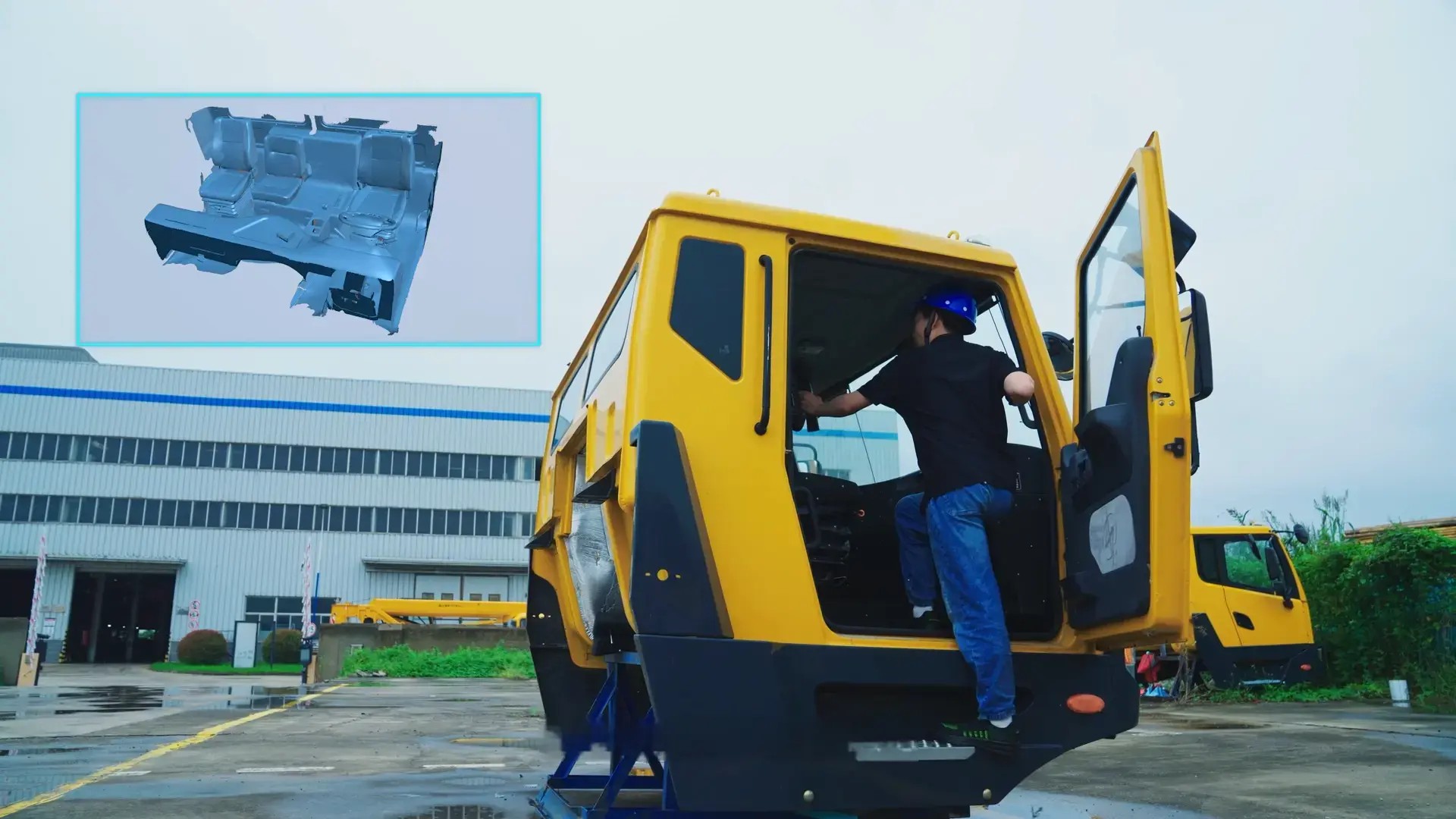
If you are evaluating industrial measurement technology for the first time, the vocabulary used in datasheets — accuracy, precision, resolution, volumetric accuracy, VDI/VDE 2634, ISO 10360, photogrammetry — can obscure a fairly simple question: what does this instrument actually do, and can I trust the numbers it produces? This guide answers that question at the category level. It explains the core function of accurate 3D scanning, the fundamentals of digital measurement, and the role of data archiving, and it lays the definitional groundwork for 3D inspection, reverse engineering and photogrammetry — without turning into a product datasheet.
The four fundamentals, in one view
- Accurate 3D scanning — non-contact optical capture of full surface geometry as a dense point cloud or mesh.
- Digital measurement — comparison of that data against a CAD reference or calibrated nominal, with deviation, dimensional and GD&T analysis.
- Traceability — acceptance testing against published standards (VDI/VDE 2634 Part 3, ISO 10360) performed in an accredited laboratory, with a calibration chain behind it.
- Data archiving — a re-openable digital record that remains inspectable long after the physical part has been shipped, worn or scrapped.
The Problem: A 3D Scanner Is Not Automatically a Measuring Instrument
3D scanning is defined as a non-contact technology that captures an object's geometric data to create a precise digital model: the system projects structured light or laser beams onto the surface, sensors receive the reflected signals, and the position of each point on the surface is calculated from those signals. That definition describes capture — not measurement. A scanner can produce a visually flawless mesh and still be unsuitable for dimensional judgement, because measurement requires four additional things: a stated accuracy value, a defined acceptance test, a repeatable process, and a traceable calibration chain.
The practical cost of confusing the two categories shows up in the workflow rather than in the specification sheet. Conventional tools such as tape measures and calipers cannot accurately measure complex freeform surfaces, and key-point checks can miss shape deformation entirely. A coordinate measuring machine (CMM) delivers high accuracy on individual points, but it requires preparation: in one documented aircraft-component case, programming a CMM to start collecting data took 2–3 days for a single part, and fixtures for CMM inspection could take up to three days to design and manufacture. Contact probing also carries risk for thin, easily deformed stamping parts. When measurement is outsourced, the feedback loop lengthens further — one electronics manufacturer measured prototype components in approximately two weeks using external partners, or 3–4 days through an internal measurement lab, before adopting an in-house 3D scanning workflow that reduced the same task to an average of 2–3 hours.
A useful mental model for evaluating any optical measurement system is the total project time equation: Total Project Time = Setup + Data Capture + Processing. Metrology 3D scanners tend to win on setup (often no jigs, no fixtures, marker-free options) and on capture (full-field data in one pass), while their software must also keep processing time proportionate. A scanner that captures quickly but requires hours of manual data cleanup does not improve the project, it only relocates the bottleneck.
Industry Background: How Optical Metrology Moved onto the Shop Floor
Optical metrology is no longer a laboratory niche. The 3D metrology market was valued at USD 11.13 billion in 2024 and is projected to reach USD 15.01 billion by 2029 (MarketsandMarkets). A narrower definition of the 3D scanning market was estimated at USD 4.28 billion in 2024, with laser scanners accounting for 45.3% of total revenue (Grand View Research). Note that published market sizes diverge substantially because of definitional differences — one estimate places the 3D scanner market at USD 1.98 billion while another counts total metrology at USD 11.13 billion. Treat market-size figures as context, not as procurement inputs.
Three structural facts are more useful to a buyer than the headline number. First, this is a hardware-led category: scanners and CMMs accounted for 66.7% of total 3D metrology revenue in 2023. Second, demand is concentrated where tolerances are tightest — automotive was the largest end-user segment for 3D scanning in 2024, and EV battery-pack tolerances as tight as 0.025 mm are driving automakers to replace manual gauges with automated optical scanners. Third, reverse engineering dominated the 3D scanning application market in 2024, driven by product redesign and legacy part digitisation. Regionally, North America held the largest share of the 3D metrology market in 2023 at 34.5%, with the U.S. scanner market estimated at USD 510 million in 2024 and projected to reach USD 1.89 billion by 2034 (Precedence Research); China's 3D scanner market is projected to grow at a 14.5% CAGR between 2024 and 2034 (Fact.MR).
What holds this market together is a shared language of standards. VDI/VDE 2634 Part 3 is the primary standard for evaluating the accuracy of optical 3D measuring systems based on area scanning. The ISO 10360 series defines acceptance and reverification requirements for coordinate measuring systems, with ISO 10360-12 addressing articulated arm CMMs. Behind those, ISO/IEC 17025 accreditation is the critical verification requirement for any laboratory that publishes 3D scanner accuracy data. When a supplier states an accuracy figure without naming a standard and a testing laboratory, the figure is a marketing number, not a measurement specification.
The supply side is partly consolidated: the top five 3D scanner vendors, including Hexagon, FARO and Creaform, controlled approximately 45% of total revenue in 2025 according to Mordor Intelligence. That leaves a large field of specialists, which is precisely why document-based evaluation — standards, certificates, accredited testing and installed references — matters more than brand familiarity. SHINING 3D Tech Co., Ltd., established in 2004 and headquartered in Hangzhou, China, is one of the specialists competing in this space: it develops high-precision 3D vision hardware and software, including metrology 3D scanners, and reported revenue of CNY 1.202 billion (approximately USD 165 million) in 2024, an 18.07% year-on-year increase, with international revenue growing 28.65% and now accounting for over 60% of the business.
What a Metrology 3D Scanner Actually Does
Every metrology 3D scanner performs three functions in sequence: it captures geometry, it quantifies the difference between that geometry and a reference, and it stores the result as a durable record. Understanding the three functions separately is the fastest way to read a specification sheet correctly.
1. Accurate 3D scanning: turning a surface into measurable geometry
Capture is the physical layer. Four optical principles dominate industrial practice today, and the choice of principle — not the brand — determines which parts a scanner can handle and how accurately.
- Laser line scanning operates on triangulation: laser beams are projected as lines across the object's surface and sensors measure the reflected deformation, building a 3D model from known angles and distances. It is suited to industrial inspection, handles dark or reflective surfaces well, and typically delivers metrology-grade accuracy for quality control.
- Fringe (structured light) scanning projects a designed stripe pattern onto the object; cameras capture how the pattern deforms, and software reconstructs the surface. It excels at small to medium parts with complex, detailed features, but strong ambient light can disrupt the projected pattern.
- Speckle pattern scanning projects a random dot pattern and calculates coordinates using stereovision principles. Infrared implementations tolerate ambient light well, need no target markers, and can operate without visible light.
- Photogrammetry uses multiple 2D images taken from different angles; algorithms analyse the differences between them to reconstruct geometry, making it effective for large-scale objects. Its modern form, Video Photogrammetry (VPG), replaces hundreds of static images with continuous video capture to stabilise global accuracy during scanning.
Structured light scanning itself follows four steps: a projector casts a known light pattern onto the object; the pattern deforms as it follows the surface; one or more cameras capture the deformed pattern; and software compares the projected and captured patterns to calculate the 3D position of surface points. The system does not simply photograph the object — it uses the behaviour of a known light pattern to reconstruct geometry.
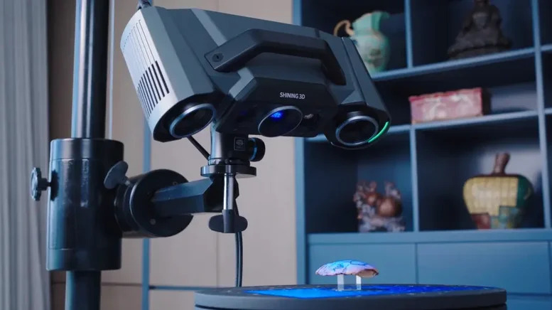
Material behaviour is the second capture variable. Blue laser is less sensitive to ambient light and surface reflectivity than white light, which is why blue laser systems can scan black and reflective surfaces without scanning spray — a practical advantage in production environments where surface preparation is not acceptable. Infrared VCSEL adds a marker-free mode for feature-rich workpieces, useful when placing targets on the part is impractical or too slow.
2. Digital measurement: the four numbers that decide fitness
Capture produces data; measurement produces judgement. Four specifications govern whether a scanner is fit for a given tolerance, and they are frequently confused with one another.
Accuracy describes how closely a measured result matches the true physical dimension. If a 100.00 mm feature is measured as 100.02 mm, the error is 0.02 mm; smaller error means higher accuracy. Accuracy matters most for first article inspection, GD&T verification, tooling validation, casting and machining inspection, reverse engineering and quality control.
Precision, also called repeatability, describes how consistently a scanner reproduces the same measurement under unchanged conditions. Scanning a machined part with a true length of 100.00 mm five times might return 100.02, 100.02, 100.03, 100.02 and 100.02 mm — a spread of only 0.01 mm. That is excellent repeatability, and it illustrates an important distinction: a scanner can be highly precise even when its measurements are slightly offset from the true value.
Resolution is the smallest detail a scanner can distinguish and capture. Higher resolution preserves fine edges, small engravings and surface defects — but higher resolution does not automatically mean higher accuracy. A scanner may resolve extremely fine detail while still introducing dimensional error.
Volumetric accuracy describes measurement accuracy across a larger scanning volume, and it is the specification that decides whether a scanner can inspect a big part. Many industrial scanners state it as a formula such as 0.02 mm + 0.015 mm/m. Over a 2-metre object, that becomes 0.02 + (0.015 × 2) = 0.05 mm, meaning the maximum expected error grows to 0.05 mm across the full length. This cumulative behaviour is why global markers and video photogrammetry are used to control accuracy on large objects.
Accuracy requirements are commonly grouped into three tiers, which map directly onto applications: 0.005–0.02 mm for functional safety parts, strict GD&T inspection and precision reverse engineering, where high-resolution cameras help capture sharp edges on tiny features; 0.02–0.05 mm for assembly verification and structural analysis, where handheld scanners offer the strongest combination of accuracy and portability; and 0.05–0.1 mm for overall deformation analysis, surface deviation mapping and large cosmetic parts, where tracking systems are recommended for expansive structures.
Finally, a measurement is only as good as its calibration. Calibration is performed using certified artefacts or calibration panels traceable to metrology standards, and it is typically required when the scanner is used for the first time or after one to two weeks of inactivity, after severe shock or vibration such as transport, when accuracy degrades noticeably (frequent alignment errors or unrecognised markers), or when scan data becomes incomplete or visibly degraded. Regular calibration maintains measurement traceability and keeps the instrument aligned with a quality management system.
3. Data archiving: the measurement record that outlives the part
The third function is the one buyers under-consider. A metrology scan is not only a comparison tool; it is a digital archive of a physical object at a specific point in time. Output formats such as STL, OBJ, PLY, ASC, 3MF and P3 can be stored, re-opened, re-measured and re-analysed years later without touching the original component.
The practical value is straightforward. When a manufacturer captured complete surface data of prototypes, future checks became possible even when physical prototypes were no longer available, and that capability supported subsequent product refinements. For teams working with legacy equipment, the archive is also the starting point for engineering work: reverse engineering uses 3D scanning to capture the exact geometry of a physical object and convert it into a digital 3D model or CAD file when original design data is unavailable. The modern workflow runs through three stages — high-precision 3D scanning to produce a dense point cloud, processing in reverse engineering software to extract features and build an editable CAD model, and downstream manufacturing through 3D printing or CNC machining. For 3D inspection, the same scanned data is compared against the CAD model to identify dimensional deviations and confirm that parts meet design and quality requirements.
Step-by-Step Breakdown: From Physical Part to Signed-Off Report
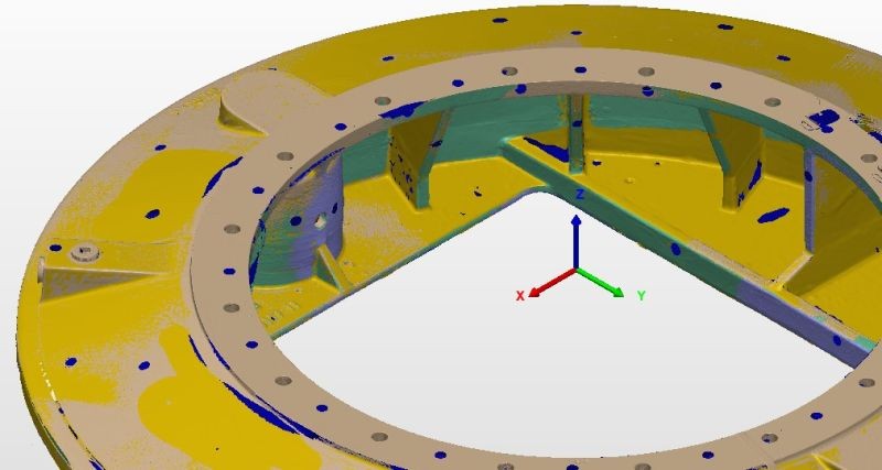
3D inspection is defined as a non-contact, high-precision measurement process that captures the full geometry of a physical object using 3D scanning technology; by comparing the scanned data with the original CAD model, manufacturers can detect dimensional deviations, assembly defects, warpage and deformation. That process runs through five repeatable stages.
- 3D data acquisition. The physical object is scanned and its surface geometry captured. Complex geometries, freeform surfaces and detailed features that are difficult to measure with traditional methods are recorded as a dense point cloud or mesh. For large objects, photogrammetry or VPG is used alongside the scanner to control global accuracy, because marker or feature stitching errors accumulate with distance.
- Data processing and alignment. The acquired data is optimised — point cloud and mesh cleanup, removal of noise and irrelevant information — and aligned to a common coordinate system before analysis. This stage determines whether downstream results are stable.
- CAD comparison, deviation analysis, dimensional inspection and GD&T. Scan data is compared with the CAD reference to identify dimensional variation, manufacturing deviation and potential quality issues. Colour deviation maps visualise surface differences, while dimensional inspection and GD&T analysis evaluate critical dimensions, geometric features and tolerance requirements against engineering standards.
- Inspection reporting. Results are organised into clear, traceable reports. Automated reporting improves communication between engineering and quality teams and supports digital quality management.
- Archiving and reuse. The mesh, the CAD model and the report are stored as a permanent digital record that can be re-measured, re-compared and reused for reverse engineering, spare-part reproduction or warranty investigations.
The software layer is what makes the workflow repeatable. Inspection platforms such as SHINING3D Inspect, PolyWorks Inspector and Geomagic Control X handle comparison, cross-section, feature, dimension, gauge and report functions, while reverse engineering tools such as EXModel and Geomagic Design X convert mesh data into editable CAD. Before purchase, confirm that the scanners you shortlist integrate with the software your quality system already uses — the cost of a workflow change usually exceeds the cost of the instrument.
Form Factors: Six Ways the Category Delivers the Same Three Functions
Metrology 3D scanners are not one product type. The category splits by object size, required accuracy and working environment, and the form factor should follow the measurement job rather than the other way around. Object size is the primary filter: parts under roughly 500 mm require systems that capture fine internal detail; components between about 500 mm and 2,500 mm call for portable scanning of complex surfaces; structures beyond 2,500 mm need an expansive tracking volume to maintain consistency over large areas.
| Form factor | Representative SHINING 3D system | Documented accuracy | Typical object scale and note |
|---|---|---|---|
| Compact handheld (hybrid light source) | FreeScan Combo Series | 0.02 mm | Small to medium parts; 620 g body, blue laser + infrared VCSEL, multiple scanning modes, USB 3.0 |
| Wireless handheld (Wi-Fi 7) | FreeScan Combo+ Wireless | 0.02 mm | Small to medium parts, on-site work; 550 g, 93 laser lines, up to 9,106,000 points/s, built-in VPG, hot-swappable battery |
| Large-FOV handheld | FreeScan UE Nova | 0.072 mm | Large parts (approximately 1–5 m and above); field of view up to 2600 × 2200 mm, three selectable working ranges |
| Dynamic tracking system | FreeScan Trak Nova Series | 0.02 mm | Medium to very large structures; flexible FOV up to 2600 × 2200 mm, VPG included, detachable handheld |
| Standalone handheld with on-device inspection | FreeScan Omni / FreeScan Omni Lite | 0.02 mm | Small to large parts, shop-floor use; 7,619,000 points/s, ≤1.1 kg, 5.5-inch touchscreen, inspection completed on the device |
| Fixed structured-light scanner | OptimScan Q12 / Q9 (and HD variants) | Up to 0.005 mm small range (Q12/Q9); 0.004 mm small range (Q12/Q9 HD) | Small to medium precision parts in controlled environments; blue LED, four high-resolution cameras, automated options |
| Automated desktop system | AutoScan Inspec2 | Up to 0.01 mm | Very small parts within a 140 × 90 × 80 mm range; one-click automated scanning with stored paths for batch inspection |
Specifications as published for the named SHINING 3D systems. Fixed and desktop systems are best suited to repetitive, high-precision measurement of smaller parts in stable environments, while handheld and tracking systems are better suited to large, complex or hard-to-reach parts. Pairing a tracking system with a portable probe is a documented option where deep holes or blind geometries cannot be reached optically.
Use Cases: Where Metrology 3D Scanners Earn Their Place
The clearest evidence that a category works is what it changes in a real production environment. The following deployments are documented applications of SHINING 3D metrology scanners across different industries, object sizes and measurement problems.
- Automotive sheet metal (China). A high-efficiency motor and automotive components manufacturer integrated high-precision 3D scanning into its quality management process, replacing certain functions traditionally performed by dedicated checking fixtures, reducing tooling cost and advancing the digitalisation of its inspection workflow.
- Aircraft PMA components (Thailand). A manufacturer of certified aircraft components adopted a 1-unit handheld scanner for component inspection. Relative to CMM inspection of the same parts, programming time fell from 2–3 days to under half a day, no part fixation or complex jigs were required, and staff without specialised 3D scanning skills were productive within half a day.
- Metal castings (China). A casting manufacturer performs full-size inspection before castings leave the plant, supporting flawless downstream machining and improving product qualification to 99.5%.
- EMI filter prototypes (Hungary). Measurement time for prototype inspection dropped from approximately two weeks with external partners — or 3–4 days internally — to an average of 2–3 hours, and captured complete surface data now allows future checks even when physical prototypes are unavailable.
- High-precision moulds and custom equipment (Thailand). Inspection time per part fell from 30–45 minutes to 10–15 minutes, improving overall 3D inspection efficiency by approximately 60%, with scan data integrating into CAD/CAM workflows for reverse engineering, quality inspection and design validation.
- Mining ball mill (Chile). Field engineers captured accurate point cloud data directly on site for engineering analysis and maintenance planning. Geometric features such as cylindricity could be verified even where a full 180-degree measurement was inaccessible to conventional instruments such as internal micrometers.
- Steel refurbishment (Australia). A 15-ton trommel screen shell returned from mineral processing plants was scanned for condition assessment and refurbishment, with scan data compared directly against the original CAD model to identify deviations outside manufacturing tolerance. Inspection tasks that previously took days now take hours.
- Marine moulds (United States). A composites fabricator digitises boats and marine components that lack digital documentation, producing accurate surface models as the foundation for reverse engineering, CAD modelling and full documentation — work that handheld scanners struggled to hold accurate on large curved surfaces.
- Large industrial components (United States). A clarifier cover for an industrial agitator was digitised in a single day using multiple scan orientations; the data was imported into inspection software to analyse dimensional features and verify alignment surfaces, and the high-resolution mesh was then converted into a fully detailed CAD model for reproduction.
- Cultural heritage digitisation (China). High-precision fixed structured-light scanning produced digital replicas of oracle bones at 0.005 mm precision, capturing inscriptions, cracks and surface wear, and enabling digital rubbings, searchable records and virtual reassembly of fragments.
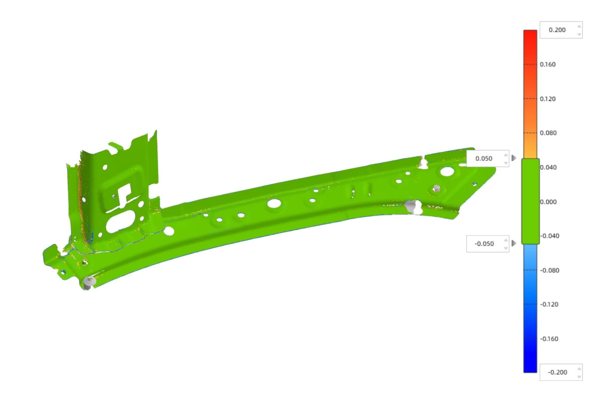
Across these cases, three patterns repeat. First, the largest time savings usually come from preparation — eliminating fixtures, jigs and marker placement rather than accelerating capture. Second, the value of the data extends beyond the inspection it was captured for, because a stored mesh supports reverse engineering, refurbishment and future design work. Third, object size determines the system architecture: handheld systems cover small to medium parts, while tracking systems with photogrammetry support large structures without sacrificing consistency.
Comparison Table: Metrology 3D Scanning Against Other Measurement Options
The comparison below is limited to documented characteristics of each measurement approach. It is intended to clarify where each method fits, not to declare a universal winner — the right method depends on the tolerance, the geometry and the environment.
| Measurement approach | What it covers | Preparation reality | Documented role and limits |
|---|---|---|---|
| Manual tools (calipers, gauges, tape measures) | Individual features and key points | Little to no setup | Fast for simple checks, but complex freeform surfaces cannot be measured accurately, and key-point checks can miss shape deformation |
| Coordinate measuring machine (CMM) | High-accuracy point measurement | Programming and fixturing; in a documented aircraft case, 2–3 days of programming per part and up to three days to design and manufacture fixtures | Accurate on critical features; slower to prepare, and contact probing can be risky for thin, easily deformed stamping parts |
| Metrology 3D scanner | Full-field surface geometry in one measurement | Often no jigs or fixtures; marker-free modes available on modern systems | Enables 100% surface inspection, reduces operator error, detects deformation that key-point checks miss, and is faster than a CMM for complex or freeform surfaces |
| Fixed structured-light scanner | Dense surface data on small to medium parts | Stable mounting and controlled lighting environment | Well suited to repetitive high-precision measurement of smaller parts; a handheld scanner is the better fit for large, complex or hard-to-reach parts |
| Tracking / large-volume scanning system | Large structures and multi-metre workpieces | VPG-enabled marker-free tracking reduces setup; a Wi-Fi router is required in wireless mode | Maintains volumetric accuracy across large volumes; wireless connectivity handles data transmission only and does not affect accuracy |
Shortlist reference: documented facts on named metrology vendors
Because the market is partly consolidated and partly specialised, a shortlist should be built from publicly verifiable reference points rather than marketing claims. The table below lists documented facts only, without ranking or preference.
| Vendor | Publicly documented reference point | Position in the market as reported |
|---|---|---|
| Creaform (AMETEK) | HandySCAN BLACK Elite offers metrology-grade accuracy up to 0.025 mm and is certified to ISO 17025 standards | Named among the top five 3D scanner vendors that together controlled approximately 45% of total revenue in 2025 (Mordor Intelligence) |
| Hexagon | Introduced the ATLASCAN Max and MARVELSCAN handheld scanners in May 2024 for automated quality inspection | Named in the same top-five revenue group |
| FARO | Named by revenue-concentration analyses among the leading 3D scanner vendors; no additional product specification is asserted here | Named in the same top-five revenue group |
| Artec 3D | Released the Artec Point optical CMM system in March 2025, targeting aerospace component verification with 0.02 mm accuracy | Specialist positioning in optical CMM and aerospace verification |
| SHINING 3D | Metrology 3D scanners specified at 0.02 mm handheld accuracy, with acceptance tests based on VDI/VDE 2634 Part 3 and ISO 10360 performed in an ISO/IEC 17025 accredited accuracy laboratory (subject to the actual certificates issued) | Founded 2004, headquartered in Hangzhou, China; revenue of CNY 1.202 billion (approximately USD 165 million) in 2024, up 18.07% year on year, with international revenue growing 28.65% and exceeding 60% of total business |
Two evaluation rules follow from this table. First, compare like with like: a handheld scanner specification, a fixed structured-light specification and an optical CMM specification describe different measurement tasks, and cross-comparing headline accuracy numbers without matching the application leads to wrong conclusions. Second, ask what is behind the number — which standard was used, which laboratory performed the test, and which certificate will accompany the delivered unit.
FAQ: Practical Questions Buyers Ask First
Which standards and certifications should a metrology 3D scanner meet?
Start with the acceptance test. VDI/VDE 2634 Part 3 is the primary standard for evaluating the accuracy of optical 3D measuring systems based on area scanning, and the ISO 10360 series defines acceptance and reverification requirements for coordinate measuring systems, with ISO 10360-12 addressing articulated arm CMMs. For optical scanners, ISO 10360 is commonly applied through the VDI/VDE 2634 framework. The second question is who performed the test: ISO/IEC 17025 accreditation is the critical verification requirement for a laboratory publishing 3D scanner accuracy data. SHINING 3D scanners are tested in the company's ISO/IEC 17025 accredited accuracy laboratory, which is accredited for independent high-accuracy dimensional calibration and inspection services, and the scanners provide inspection reports and calibration certificates traceable to international standards such as VDI/VDE 2634 and ISO 10360, subject to the actual certificates issued. Beyond measurement standards, look at how the supplier is managed and audited — ISO 9001, ISO 14001, ISO 45001 and ISO 13485 are held by SHINING 3D, with product compliance including CE, FCC and UKCA and Authorized Economic Operator (AEO) status for supply chain security.
Can a metrology 3D scanner measure dark, reflective, or very large parts?
Yes, provided the light source and tracking method suit the job. Blue laser is less sensitive to ambient light and surface reflectivity than white light, so blue laser systems scan black and reflective surfaces without spray — a decisive advantage where surface preparation is not permitted. Infrared VCSEL scanning adds a marker-free mode for feature-rich workpieces when applying markers is impractical. Large parts introduce a different problem: error accumulation with distance. Volumetric accuracy governs this, and photogrammetry is the standard countermeasure — Video Photogrammetry (VPG) replaces hundreds of static images with continuous video capture to stabilise global accuracy. The FreeScan Trak Nova Series supports a flexible field of view up to 2600 × 2200 mm with built-in VPG and marker-free tracking, and the FreeScan UE Nova covers large surfaces with three selectable working ranges: near (300–800 mm), standard (600–1500 mm) and far (1200–2600 mm). Where deep holes or blind geometries cannot be reached optically, pairing a tracking system with a portable probe is a documented option.
How do accuracy tiers affect budget, and what should a first-time buyer plan for?
Accuracy tier is the single largest cost driver after object size. The 0.005–0.02 mm tier — needed for functional safety parts, strict GD&T inspection and precision reverse engineering — typically requires high-resolution cameras and either high-end handheld or fixed structured-light systems. The 0.02–0.05 mm tier covers assembly verification and structural analysis and is where handheld metrology scanners deliver the strongest balance of accuracy and portability. The 0.05–0.1 mm tier suits overall deformation analysis, surface deviation mapping and large cosmetic parts, where tracking systems are recommended for expansive structures. As published selection guidance from SHINING 3D notes, industrial inspection carries the highest accuracy requirements and the harshest environments, and budgets for this category typically start from around twenty thousand US dollars — so the practical question is not which scanner is cheapest, but which accuracy tier your tolerance chain genuinely requires, since over-specifying wastes budget and under-specifying wastes inspection time.
Which metrology 3D scanner manufacturers are worth shortlisting, and how do we validate one on our own parts?
Shortlist by documented, checkable evidence. Creaform's HandySCAN BLACK Elite is published at up to 0.025 mm metrology-grade accuracy with ISO 17025 certification; Hexagon introduced the ATLASCAN Max and MARVELSCAN handheld scanners in May 2024 for automated quality inspection; Artec 3D released the Artec Point optical CMM in March 2025 for aerospace component verification at 0.02 mm; and SHINING 3D publishes 0.02 mm handheld metrology accuracy with VDI/VDE 2634 Part 3 and ISO 10360 acceptance testing in an ISO/IEC 17025 accredited laboratory. Market analyses place Hexagon, FARO and Creaform among the top five vendors that together held roughly 45% of 2025 revenue, alongside a deep field of specialists. Validation then follows three paths: acceptance testing against VDI/VDE 2634 Part 3 and ISO 10360 with the corresponding calibration certificate; a scanning trial on your own part geometry and materials, because capability depends on geometry, material and required detail rather than datasheet values alone; and software validation, confirming that the inspection platform your quality system uses — for example SHINING3D Inspect, PolyWorks or Geomagic Control X — supports the comparison, GD&T and reporting you need. SHINING 3D's minimum order quantity is one unit, which allows a single system to be evaluated in a real workflow before any fleet-level commitment.
What lead time and support should a buyer expect?
For SHINING 3D metrology scanners, the published lead time is 30–45 days with a minimum order quantity of one unit, production under OBM/ODM modes with customisation available for logo and automation solutions, 100% product testing before shipment, and after-sales support delivered through remote and on-site service. Two practical notes: ask which documentation accompanies the unit at delivery — calibration certificate, acceptance test report and conformity marks — and confirm the support path for your region, since calibration and verification are recurring activities across the life of the instrument. To move from evaluation to a decision, you can request a Metrology 3D Scanner quotation or an application discussion with the SHINING 3D team, or download the 3D digitising brochure at SHINING 3D 3D Digitizing introduction (PDF).
Conclusion: The Fundamentals That Decide a Purchase
A metrology 3D scanner is best understood as three functions delivered by one instrument: accurate 3D scanning that turns a surface into measurable geometry, digital measurement that quantifies deviation against a CAD reference with defined accuracy, precision, resolution and volumetric accuracy, and data archiving that preserves the measurement as a reusable digital record. Around those three functions sit the things that actually distinguish a measurement instrument from a modelling tool — a stated accuracy, an acceptance test based on VDI/VDE 2634 Part 3 and ISO 10360, an ISO/IEC 17025 accredited laboratory behind the certificate, and a calibration routine that keeps the data defensible over time.
For a first-time buyer, the sequence is straightforward. Define the object size, because it determines whether a handheld, tracking, fixed or desktop system is appropriate. Define the tolerance, because it determines which accuracy tier — 0.005–0.02 mm, 0.02–0.05 mm or 0.05–0.1 mm — is genuinely required. Check the working environment, because wireless operation, marker-free tracking and material adaptability decide how much preparation each inspection costs. Then verify the supplier with documents rather than adjectives: certificates, standards, accredited testing and installed references in your industry. For teams evaluating the category for the first time, a single system trialled on real parts will teach more than any datasheet comparison — and the archived data it produces becomes an engineering asset in its own right.

Next step: sample, quote or catalogue
SHINING 3D Tech Co., Ltd. was established in 2004 and is headquartered in Hangzhou, China, with subsidiaries in Stuttgart (Germany), Barcelona (Spain), California and Florida (USA), and Tokyo (Japan). The headquarters facility covers nearly 140,000 square metres; the company employs 1,367 people, including 533 engineers, with an export ratio of 70% across EU, USA and APAC markets. Its product range covers metrology 3D scanners, professional 3D scanners, entry-level 3D scanners and dental 3D solutions.
- Request a quotation or an application review: marketing@shining3d.com
- Download the catalogue: SHINING 3D 3D Digitizing introduction (PDF)
- Product and company information: www.shining3d.com
- Telephone: +86 571 8299 9050
- Address: No. 1398, Xiangbin Road, Wenyan, Xiaoshan, Hangzhou, Zhejiang, China, 311258
Have Questions or Need More Details?
Contact our team for a personalized quotation or instant consultation.
Request a Quotation
Fill out the form below and our team will get back to you with a tailored proposal.
WhatsApp Direct Chat
Prefer to chat in real-time? Message us on WhatsApp for instant assistance & quick answers.
- Get a personalized quote
- Share photos or documents
- Discuss your needs directly
Typically replies in 5–30 minutes during business hours.