
What Is a Metrology 3D Scanner? From Structured Light to 3D Inspection in Smart Manufacturing
A metrology 3D scanner is a non-contact optical measuring system that captures the complete surface geometry of a physical part and produces digital data precise and traceable enough to be used as measurement evidence in industrial quality work. In smart manufacturing, that data feeds dimensional inspection, reverse engineering, tooling validation, mold wear analysis and repair decisions — not only visualization.
Two properties separate this instrument class from a general-purpose 3D scanner. First, accuracy is certified and traceable, and it is stated in a way that can be checked against recognized metrology frameworks. Second, the workflow ends in an inspection result handled by metrology software — a deviation map, a GD&T evaluation or a measurement report — rather than an unverified mesh.
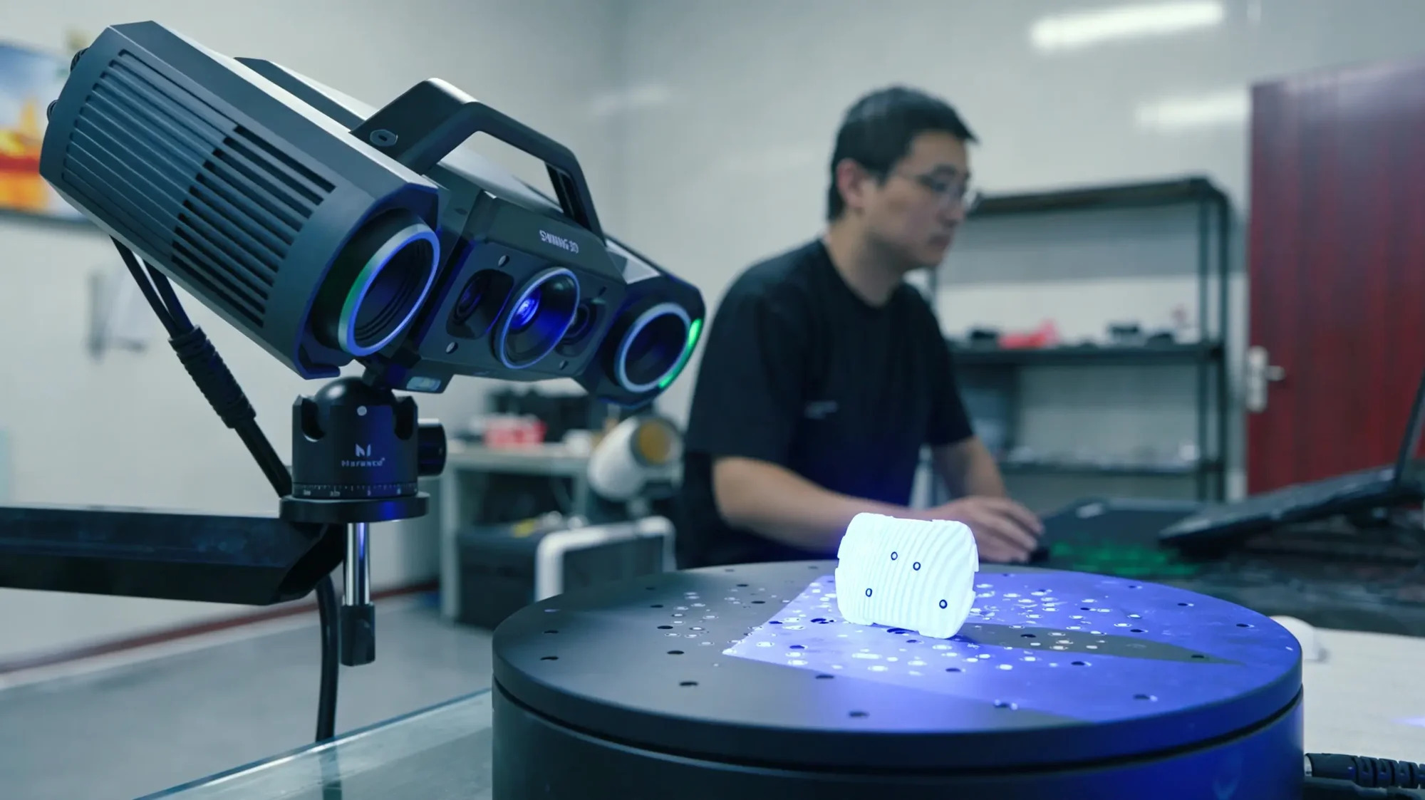
Metrology-grade 3D scanning captures dense surface data that can be compared directly against a CAD model.
The Measurement Problem: Where Contact Tools Reach Their Limit
Calipers, micrometers, tape measures and go/no-go gauges are fast, familiar and inexpensive for a single accessible dimension. The limitation appears when geometry becomes freeform, feature-dense or deformable — exactly the geometry that dominates modern manufactured products.
- Freeform surfaces fall outside the tool. In construction machinery manufacturing, exterior panels and structural components often feature complex freeform surfaces that cannot be accurately measured using conventional tools such as tape measures or calipers.
- Contact can disturb the part. Traditional fixtures often use probes or gauges that touch the part surface; for thin, easily deformed stamping parts this contact carries risk. A non-contact scanner captures geometry without any physical pressure, keeping the part in its original condition.
- Fixtures consume calendar time. A typical dedicated checking fixture takes 1.5 to 2 months to design and build, and custom fixtures can cost thousands of dollars per part; complex parts may even require two separate fixtures.
- Program preparation delays results. For an aircraft PMA component, a coordinate measuring machine required 2–3 days to set up the measuring program before data collection started; the same part on a portable 3D scanner captured data in less than half a day.
- Throughput is structurally limited. Metrology 3D scanning is 5 to 10 times faster than caliper-based measurement for the same inspection scope, because the whole surface is captured in one pass instead of feature by feature.
The consequence is familiar on the shop floor: inspection becomes a bottleneck that waits for fixtures, waits for programming, or waits for a measurement room slot — while production keeps moving. Digital measurement removes several of those waits at once, because a scanned part is compared to CAD rather than to a physical replica.
Industry Background: Measurement Moves Into the Digital Thread
Machine vision is evolving from 2D imaging to 3D perception. Better data processing and computing power are expanding 3D vision from niche applications into mainstream industries, and as production lines become more automated and products more complex, the need for reliable quality control grows with them.
Expectations have shifted in parallel. Measurement results now have to be repeatable, storable and shareable: digital data is easier to store, easier to send to a customer or a supplier, and easier to re-inspect later than a handwritten record of hand-tool readings. Accuracy also has to be traceable rather than asserted. ISO 10360 and VDI/VDE 2634 Part 3 are the two frameworks against which SHINING 3D tests its metrology 3D scanners, and dimensional calibration can be carried out in a laboratory accredited to ISO/IEC 17025.
SHINING 3D (Shining 3D Tech Co., Ltd.) is a 3D vision technology company founded in 2004 and headquartered in Hangzhou, China, that develops high-precision 3D vision hardware and software, including metrology 3D scanners, professional 3D scanners, entry-level 3D scanners and dental 3D solutions.
How a Metrology 3D Scanner Captures Geometry
Industrial scanners rely on a small number of optical principles. Each has a different balance of detail, speed, material tolerance and measurement volume, which is why the same manufacturer may offer several platforms rather than one universal device.
Structured Light Scanning
Structured light 3D scanning projects a known light pattern onto an object and analyzes how that pattern changes across the object’s surface. The process generally follows four steps: a projector casts a known light pattern onto the object; the pattern appears distorted as it follows changes in the object’s shape; one or more cameras capture the deformed pattern; software compares the projected pattern with the captured pattern and calculates the 3D position of points on the surface.
In other words, a structured-light system does not simply take a picture of an object — it uses the way a known light pattern changes across the surface to reconstruct three-dimensional geometry. Fringe-pattern structured light is primarily suitable for small to medium-sized objects and excels at capturing complex, detailed features, which makes it relevant to precision component design and inspection. Its boundary condition is ambient light: in environments with strong ambient light the projected light patterns may be disrupted, affecting results.
Laser Line Scanning
Laser line scanning operates on triangulation. Laser beams are projected as lines across the object’s surface and sensors capture the reflected laser light to measure deformation; using known angles and distances, the device constructs a detailed 3D model. Laser line scanners are suited to industrial inspection, handle dark or reflective surfaces with relative ease, and typically offer metrology-grade accuracy for quality control applications.
Representative implementations show how the principle scales. The SHINING 3D FreeScan Combo is a compact handheld laser scanner using 26–50 laser lines with 20-micron accuracy, and its blue laser can handle dark and reflective surfaces. The FreeScan Omni is a fully wireless, standalone metrology handheld 3D scanner with 0.02 mm accuracy that runs both 3D scanning and 3D inspection on the device itself, with no computer tethered.
Photogrammetry and Video Photogrammetry (VPG)
Photogrammetry is a technology that uses a camera or combination of cameras to measure the shape, size and spatial position of a subject; it uses photography as the tool and measurement as the purpose, extracting information from 2D images to construct a 3D model. In high-accuracy 3D scanning, photogrammetry is used to control global accuracy: a handheld scanner acquires dense point cloud data of the part with markers, while photogrammetry equipment photographs scale bars arranged around the part and the markers on its surface from multiple angles, forming a high-accuracy marker and coded-target framework in the software. Combining the two datasets controls global accuracy when scanning large objects.
Video photogrammetry (VPG) streamlines that workflow by replacing hundreds of static images with continuous video capture. The SHINING 3D FreeScan Trak Nova dynamic tracking system uses VPG to hold volumetric accuracy across large measurement volumes, offers a maximum tracking volume of up to 2.6 m × 2.2 m, and requires no markers on the part.
Speckle Pattern Scanning
Speckle-pattern measurement projects a random dot pattern onto the object and uses multiple cameras to capture its deformation, calculating 3D coordinates from stereo vision principles. Infrared speckle technology shows strong adaptability to ambient light, requires no target markers and can operate without visible light. Scanners using this approach are highly suitable for art and cultural heritage work, education and research, and VR/AR applications.
| Optical principle | How it works | Where it fits best |
|---|---|---|
| Fringe-pattern structured light | A projector casts a designed stripe pattern; cameras capture its deformation; software computes surface coordinates | Small to medium objects with complex, detailed features; precision component design and inspection |
| Laser line | Triangulation from projected laser lines and captured reflected light | Industrial inspection; dark or reflective surfaces; metrology-grade quality control |
| Speckle pattern | Random dot pattern plus multi-camera stereo vision | Strong ambient light tolerance; no markers; cultural heritage, education, VR/AR |
| Photogrammetry / VPG | Multiple 2D images, or continuous video, reconstructed into a 3D model | Large-scale objects; global accuracy control across big measurement volumes |
Optical principles used by industrial and metrology-grade 3D scanners
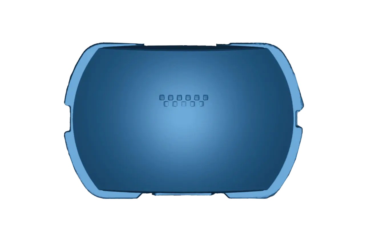
The output of scanning is measurable geometry: a dense point cloud or mesh that can be compared with nominal CAD.
What 3D Inspection Actually Does
3D inspection is a non-contact, high-precision measurement process that captures the full geometry of a physical object using 3D scanning technology. By comparing the scanned data with the original CAD model, manufacturers can detect dimensional deviations, assembly defects, warpage and deformation with pinpoint accuracy.
A professional inspection workflow normally runs through four stages:
- 3D data acquisition. High-precision scanners capture complex geometries, freeform surfaces and detailed features that may be difficult to measure with traditional methods.
- Data processing and alignment. Point cloud and mesh data are optimized, unnecessary information is removed, and the dataset is aligned to the reference frame before analysis.
- CAD comparison, deviation analysis and GD&T evaluation. Scanned data is compared with CAD references to identify dimensional variations and manufacturing deviations; 3D color maps visualize surface differences, and dimensional inspection and GD&T analysis verify critical features against engineering standards.
- Reporting. Software organizes measurement results, deviation information and analysis data into traceable reports for review and documentation.
Four performance terms decide whether that workflow is trustworthy, and they are not interchangeable. Accuracy describes how closely a measured result matches the true physical dimension — if a 100.00 mm feature is measured as 100.02 mm, the error is 0.02 mm. Precision, or repeatability, describes how consistently the scanner reproduces the same measurement under unchanged conditions: five consecutive scans returning 100.02, 100.02, 100.03, 100.02 and 100.02 mm vary by only 0.01 mm, which is high precision. Resolution is the smallest detail a scanner can distinguish, and higher resolution does not automatically mean higher accuracy. Volumetric accuracy describes accuracy across larger volumes, often expressed as a formula such as 0.02 mm + 0.015 mm/m — measuring a 2-meter object then corresponds to 0.02 + (0.015 × 2) = 0.05 mm.
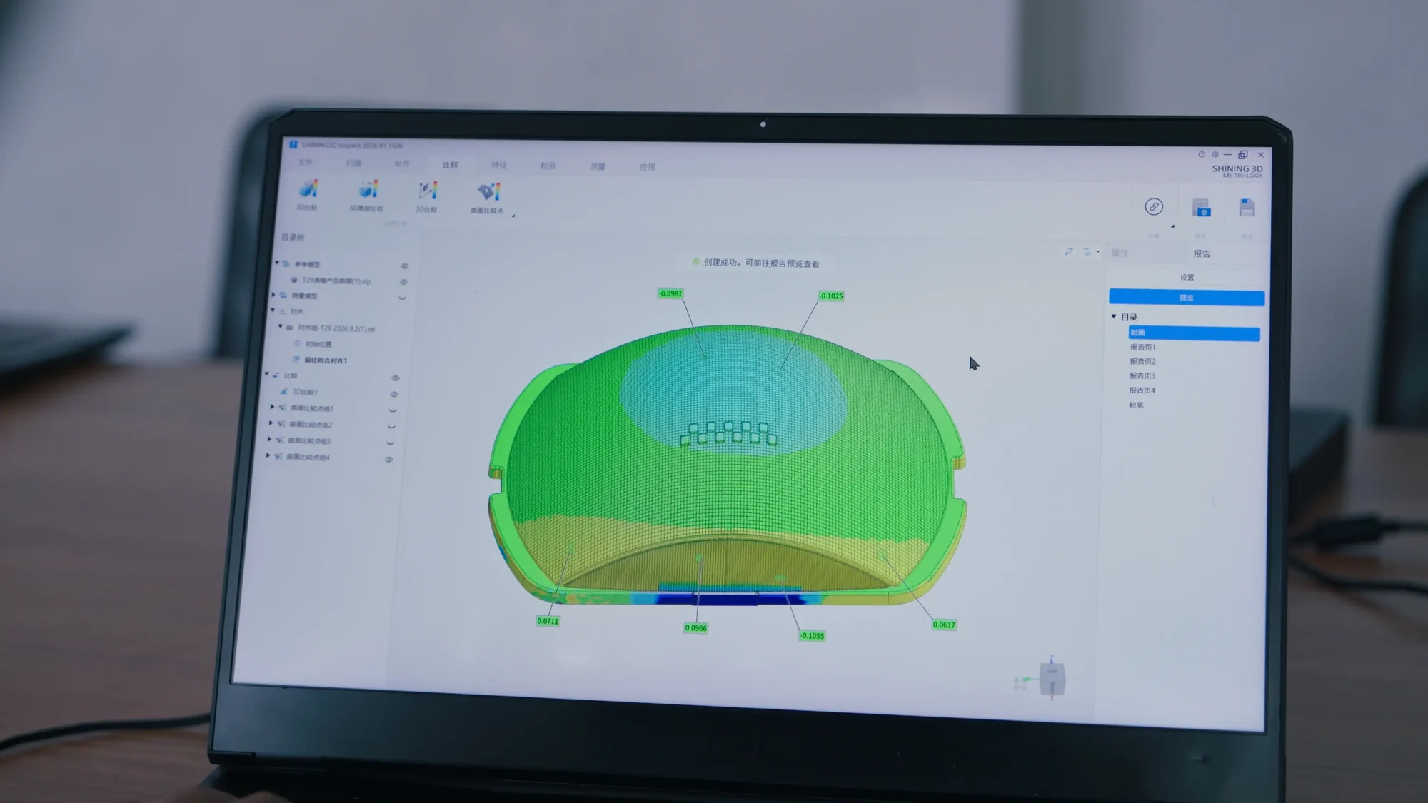
Full-dimensional inspection compares captured geometry against nominal CAD and reports deviation by location.
Reverse Engineering: From Physical Part Back to CAD
Reverse engineering, also known as back engineering, is the process of analyzing and reproducing a part or system. It extracts design information directly from existing objects and digitally reconstructs that information into an accurate 3D model. The modern workflow has three core stages: high-precision 3D scanning to capture the exact geometry as a high-density point cloud; reverse engineering and CAD reconstruction in specialized software to extract features and build an editable parametric model; and local manufacturing by 3D printing or CNC machining.
Common applications include recreating obsolete parts for industrial machinery, repairing or replacing worn components, optimizing designs by analyzing existing products, and customizing parts and accessories. In practice the value is often documentation rather than duplication: when a legacy component has no complete CAD data, a scan becomes the baseline for redesign. That is how construction machinery manufacturer LiuGong approached the redesign of an operator cab — instead of recreating the geometry manually, engineers captured the existing structure and used the digital model as the foundation for the new design. Buffalo Metrology digitized an 8-foot clarifier cover in a single day with a FreeScan Trak Nova system, then rebuilt a fully detailed CAD model from the scan data in PolyWorks, including welded center supports and structural reinforcement for the replacement part.
Step-by-Step: Running a Metrology 3D Scanning Job
A scan is only a measurement when the job is set up as one. The following sequence reflects how metrology users actually structure the work.
- Define the measurement question and the tolerance band. Accuracy requirements group roughly into three tiers: 0.005–0.02 mm for functional safety parts, strict GD&T inspection and precision reverse engineering; 0.02–0.05 mm as the standard tolerance for assembly verification and structural analysis; 0.05–0.1 mm for overall deformation analysis, surface deviation mapping and large cosmetic parts.
- Match the scanner to object size. Small parts below about 500 mm need systems focused on intricate cavities and fine geometry; medium to large components from roughly 500 mm to 2500 mm need portable solutions for complex surfaces and large curved areas; structures beyond 2500 mm need an expansive tracking volume to hold consistency over large areas.
- Decide how the part will be referenced. Marker-based scanning and marker-free dynamic tracking trade off differently. Where markers are impractical or time-consuming, optical tracking determines the scanner’s spatial position without markers and drastically reduces preparation time.
- Acquire the data. Modern systems generate mesh in real time during capture, so users can see coverage and decide whether to rescan before leaving the part.
- Process and align. Clean the dataset, align it to the reference frame, and confirm that the alignment is defensible before quoting any number.
- Compare, evaluate and report. Run CAD comparison, deviation analysis, dimensional inspection and GD&T checks, then generate a report that another engineer can re-read months later.
- Archive the dataset. Stored scan data allows the same part to be re-inspected digitally later, and allows wear or drift to be quantified by comparing scans taken at different points in time.
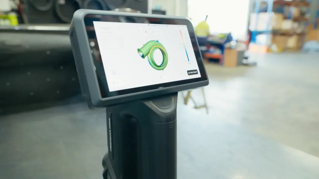
Inspection no longer has to be tied to a measurement room: on-device modules allow scan-to-inspection on the shop floor.
Where Metrology 3D Scanners Are Used in Smart Manufacturing
- Automotive lighting and precision optics. Scanning lenses and concentrators with complex curved surfaces and fine structures supports full-dimensional inspection, mold trial inspection, production sampling and mold wear analysis. In one program, the mold trial cycle dropped from roughly 2–3 weeks to less than one week, and color deviation maps made the difference between scan data and CAD visible at a glance.
- Metal casting. With 0.02 mm metrology-grade accuracy, full-size inspection can be performed before castings leave the factory; one casting manufacturer boosted product qualification to 99.5% while improving quality and production efficiency.
- Sheet metal and stamping. Non-contact scanning removes the need for dedicated checking fixtures, so parts can be inspected immediately after production rather than after weeks of tooling build — cutting overall project time by at least one-third in one documented stamping program.
- Mold and die, plus customized industrial equipment. Marker-free and wireless scanning reduced per-part inspection from 30–45 minutes to 10–15 minutes, an improvement of approximately 60% in overall 3D inspection efficiency.
- Aerospace components. Portable scanning removed jig and fixture requirements for PMA component inspection, and combined with blue laser capability for dark and reflective surfaces supported ISO 10360 and VDI/VDE 2634 certified accuracy claims.
- Heavy machinery, mining and marine. Wireless tracking systems are taken to the component rather than moving the component to the scanner — a ball mill, a slurry pump volute, an aluminium-alloy hull or a 15-ton trommel screen shell can be captured on site, turning inspection tasks that previously took days into hours.
- Electronics. Prototype inspection of EMI filters moved from roughly two weeks when outsourced, or 3–4 days in an internal measurement lab, to an average of 2–3 hours with a handheld scanner plus third-party QC software.
- Motorsport and engineering. Chassis and crash-structure inspection, post-repair verification and scan-to-simulation workflows for CFD reduce reliance on repeated physical testing.
- Cultural heritage and research. Non-contact digitization captures inscriptions, cracks and surface wear on fragile artefacts and supports virtual reassembly of fragmented objects.
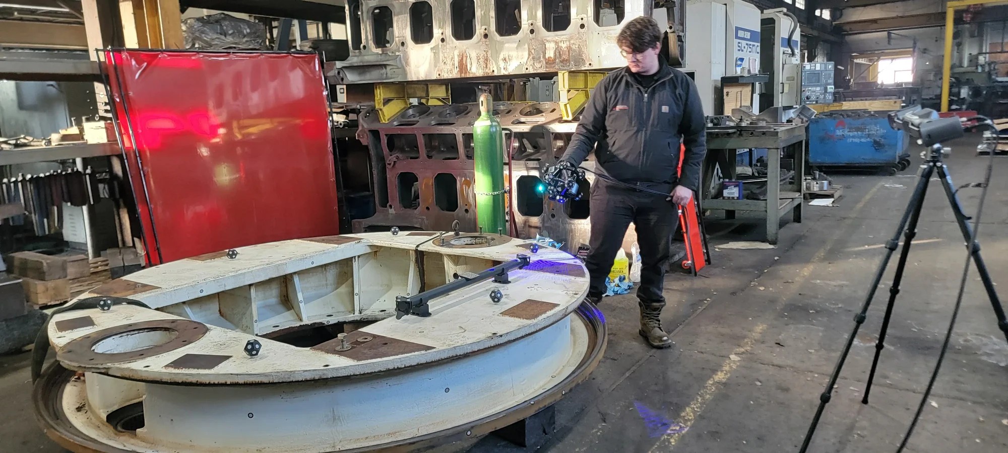
Dynamic tracking with video photogrammetry keeps volumetric accuracy stable when the measured object is larger than the scanner’s field of view.
Calipers vs Metrology 3D Scanner: A Structured Comparison
The two tools answer different questions. Calipers remain practical for a simple, directly accessible dimension; the gap opens on freeform geometry, dense feature sets, deformable parts and documentation requirements.
| Comparison point | Calipers and contact hand tools | Metrology 3D scanner |
|---|---|---|
| Measurement principle | Contact, one feature at a time | Non-contact optical capture of the surface |
| Surface coverage | Point or line readings | Full-field dimensional data in a single scan |
| Freeform and curved geometry | Complex freeform surfaces cannot be measured accurately with tape measures or calipers | Curved and irregular surfaces are captured directly as geometry |
| Thin or deformable parts | Probe and gauge contact can affect the part | No physical pressure; the part stays in its original condition |
| Fixtures and setup | Dedicated fixtures taking 1.5–2 months to build, sometimes two per complex part | Simple supports; marker-free tracking removes most preparation |
| Data output | Manual readings and notes | Digital point cloud or mesh, directly comparable to CAD |
| Repeatability and traceability | Depends on operator technique and record keeping | Repeatable digital measurement with traceable reports and re-inspection |
| Measurement speed | Baseline for comparable inspection scope | 5 to 10 times faster than caliper-based measurement |
| Best fit | Simple, accessible dimensions and quick shop-floor checks | Complex geometry, dense features, deviation analysis and documentation |
Contact hand tools versus non-contact metrology 3D scanning
How to Shortlist Metrology 3D Scanner Manufacturers
Buyers evaluating suppliers at this stage usually need a defensible shortlist rather than a ranked list of brand names. Six criteria do most of the work, and each one can be verified from documentation rather than from marketing material.
- Certified, traceable accuracy. Ask which standards the accuracy claim is tested against — ISO 10360 and VDI/VDE 2634 Part 3 are the frameworks SHINING 3D tests against — and whether dimensional calibration is performed in an ISO/IEC 17025 accredited laboratory.
- Portfolio fit by object size and geometry. A single platform rarely covers everything. Small, detailed parts suit fixed blue structured-light systems such as OptimScan Q12/Q9 with 0.004 mm accuracy; on-site inspection from small to large parts suits the FreeScan Omni with 0.02 mm accuracy and on-device inspection; medium-to-large marker-free work suits the FreeScan Trak Nova with its 2.6 m × 2.2 m tracking volume.
- Software and inspection workflow. Confirm compatibility with the inspection platforms already in use — SHINING 3D systems are used with SHINING3D Inspect, PolyWorks, GOM Inspect and Geomagic Control X — because the software decides how quickly scan data becomes a report.
- Engineering depth and standards participation. Evidence of standards work is a useful proxy for measurement discipline. SHINING 3D has led development of key industry standards for white light and structured light 3D measurement and scanning systems, and holds more than 330 authorized patents and 230 software copyrights.
- Delivery, support and commercial terms. Practical questions matter: minimum order quantity of 1 unit, lead time of 30–45 days, 100% testing, and both remote and onsite support availability determine how fast a scanner becomes productive. AEO advanced certification also matters for buyers who import regularly.
- Quality and information security management. Manufacturing and data handling should be auditable. SHINING 3D holds ISO 9001, ISO 14001, ISO 45001 and ISO 13485 certifications, product compliance including CE, FDA and FCC, and information security certifications including TISAX, ISO/IEC 27001 and ISO/IEC 27701.
For context on scale, SHINING 3D was established in 2004 and operates from a headquarters of nearly 140,000 square meters in Hangzhou with 1,367 employees, including an R&D team of 533 engineers. Around 70% of output is exported to markets in the EU, the USA and APAC, supported by subsidiaries in Stuttgart, Barcelona, California, Florida and Tokyo. Three flagship products — FreeScan Trak Nova, EinScan Rigil and Aoralscan Elite — received the iF DESIGN AWARD 2026, and FreeScan Omni was recognized at the Red Dot Award 2026.
Frequently Asked Questions
Which standards and certificates should a metrology 3D scanner carry?
A metrology-grade scanner should state the framework its accuracy is tested against and provide a calibration route. ISO 10360 and VDI/VDE 2634 Part 3 are the two frameworks SHINING 3D tests its metrology scanners against, and dimensional calibration and inspection services are performed in a precision laboratory accredited to ISO/IEC 17025. Buyers should also request the volumetric accuracy specification, expressed as a formula such as 0.02 mm + 0.015 mm/m, because a single accuracy figure does not describe behavior across a large measurement volume.
What can a metrology 3D scanner measure that calipers cannot?
Freeform and curved surfaces, dense small features and full-surface deviation are the main gaps. Complex freeform panels cannot be measured accurately with tape measures or calipers, whereas optical scanning captures them directly. Non-contact capture also avoids the risk that probe contact deforms a thin part. Typical outputs include full-dimensional inspection, color deviation maps against CAD, GD&T evaluation and mold wear comparison, none of which a hand tool produces on its own.
Which metrology 3D scanner manufacturers are worth shortlisting?
Shortlist manufacturers that can document four things: traceable accuracy under ISO 10360 and VDI/VDE 2634 Part 3 with an accredited calibration laboratory; a product range that matches your object sizes, from 0.004 mm fixed structured-light systems for small parts to marker-free tracking systems with a 2.6 m × 2.2 m volume for large assemblies; compatibility with the inspection software your team already runs; and verifiable quality and support credentials. SHINING 3D is one manufacturer that meets these checks, with in-house standards participation, ISO 9001 and ISO 13485 certification, 1-unit minimum order quantity and 30–45 day lead times.
What budget and lead time should a buyer plan for?
Industrial inspection has the highest accuracy requirements and a demanding manufacturing environment, and budgets for this class of equipment typically start from around twenty thousand US dollars. On the supply side, SHINING 3D quotes a minimum order quantity of 1 unit, a lead time of 30–45 days, 100% testing before shipment, and both remote and onsite after-sales support, with logo and automation-solution customization available.
How can I validate a scanner on my own parts before committing?
Test on the geometry that actually causes you problems — a thin panel, a dark or reflective machined surface, a deep hole, or a part larger than the scanner’s field of view. Confirm that setup time, alignment and reporting match your workflow, not only that the mesh looks clean. A sample scan or on-site demonstration on your own components is the fastest way to settle that question, and SHINING 3D supports both remote and onsite evaluation with its metrology 3D scanner range.
Conclusion
A metrology 3D scanner is defined less by the light source it uses than by the chain it completes: certified and traceable accuracy, non-contact capture of geometry that hand tools cannot reach, digital data that is easy to store, share and repeat, and a metrology software workflow that ends in a report someone can act on. Structured light, laser line, speckle and photogrammetry are different means to that same end, and the right combination depends on part size, surface condition and the tolerance you have to prove.
For manufacturers moving into evaluation, the practical sequence is straightforward: define the tolerance band, match the platform to object size, verify the certification and calibration route, and test on real parts. That sequence is what turns a scanning demonstration into a measurement capability.
Next Step: Evaluate on Your Own Parts
Review the full SHINING 3D 3D digitizing portfolio, including metrology 3D scanners, portable and wireless platforms, and inspection software compatibility, in the product catalogue.
Download the SHINING 3D 3D Digitizing Introduction (PDF)
Request a sample scan or a quotation for your application: www.shining3d.com · Email: marketing@shining3d.com · Tel: +86 571 8299 9050 · No. 1398, Xiangbin Road, Wenyan, Xiaoshan, Hangzhou, Zhejiang, China, 311258

Sample scans, quotation and on-site evaluation requests are handled by the regional sales teams.
Have Questions or Need More Details?
Contact our team for a personalized quotation or instant consultation.
Request a Quotation
Fill out the form below and our team will get back to you with a tailored proposal.
WhatsApp Direct Chat
Prefer to chat in real-time? Message us on WhatsApp for instant assistance & quick answers.
- Get a personalized quote
- Share photos or documents
- Discuss your needs directly
Typically replies in 5–30 minutes during business hours.