
CNC Machining: Spindle Speed, Feed Rate and Depth of Cut for ±0.01 mm
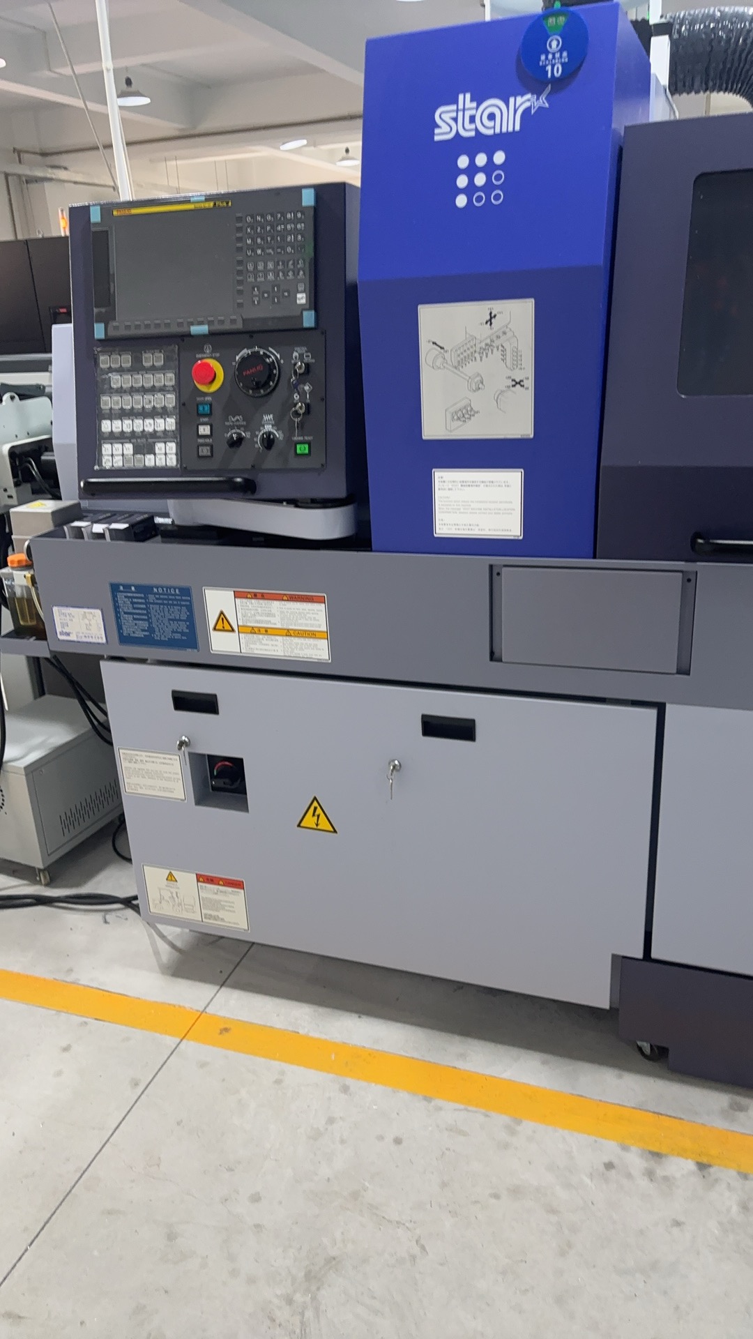
Holding ±0.01 mm in CNC machining is a cutting-parameter decision before it is a machine decision. Spindle speed, feed rate and depth of cut determine cutting force, heat and tool wear, and those three outputs decide whether a dimension lands inside tolerance and stays there across a production run.
The working answer used in precision process planning is consistent: set spindle speed from the material-specific surface-speed window, define feed rate through feed per tooth so the cutting edge always cuts instead of rubbing, and split depth of cut into a stable roughing pass plus a light, constant finishing pass. Coolant, machine condition, axis configuration and inspection then hold that setting in place.
The three-variable rule set at a glance
- Spindle speed is chosen from surface speed for the material and tool substrate, then trimmed to remove chatter and protect tool life.
- Feed rate is set from feed per tooth and tooth count, so chip thickness stays above the rubbing threshold.
- Depth of cut is controlled: roughing removes bulk with stable engagement, finishing uses a light and uniform depth.
SUNPREC HARDWARE CO.,LTD (SUNPREC) is a one-stop metal parts manufacturer established in 2020 in Dongguan City, China, offering precision CNC machining, CNC turning, die casting, extrusion and surface finishing for aerospace, automotive, medical, new-energy and industrial equipment buyers. Its CNC machining parts are specified to ±0.01 mm. This guide explains how the three variables are selected, how they change by material, and how the result is verified at that tolerance.
Problem Definition: Why ±0.01 mm Is a Parameter Problem
A ±0.01 mm tolerance is a total budget, not an allowance for the machine alone. Every source of dimensional variation draws from the same budget, and cutting parameters influence most of them.
- Machine contribution. Positioning accuracy and spindle thermal growth.
- Tool deflection. Radial cutting force bends the tool, especially with long stick-out or small diameters.
- Clamping and fixture stress. Distortion released after the part leaves the vice.
- Material condition. Hardness variation, residual stress and work hardening.
- Measurement uncertainty. Part temperature and instrument resolution at the point of inspection.
SUNPREC's FANUC CNC machining centers are specified with a machine tolerance of 0.005 mm. That figure is the machine's own contribution; the remaining budget has to cover tool deflection, clamping stress and thermal movement during the cycle, and each of those is governed by the parameters chosen. Increasing feed per tooth increases cutting force, which increases deflection. Excessive spindle speed raises temperature at the edge and in the part. Feed that is too light lets the edge rub, which work-hardens stainless steel and makes the next cut unpredictable.
The failure mode is rarely a single out-of-tolerance part. It is a process that passes first-article inspection and then drifts during a long run, because the parameters were tuned on a cold machine with a fresh tool and were never re-verified.
Industry Background: Why Parameter Discipline Is Being Audited

The global CNC machining and turning centers market was valued at USD 31.3 billion in 2026, according to Grand View Research, with Asia Pacific holding a 55.5% revenue share in 2023. Growth is concentrated in the segment that matters for tight-tolerance work: 5-axis vertical machining centers are identified as a critical high-growth segment for complex aerospace and automotive components in 2026.
Demand-side pressure comes from the same direction. The aerospace CNC machining market was reported at USD 4.7 billion in 2024 with a projected path to USD 8.8 billion by 2033 (Dataintelo). In medical manufacturing, the FDA Quality Management System Regulation has incorporated ISO 13485:2016 by reference since 2 February 2026 under 21 CFR Part 820, which moves process control, including documented and repeatable cutting parameters, into the supplier qualification file.
The practical consequence for buyers is a change in the question. It is no longer only whether a shop can reach ±0.01 mm, but whether it can show how the parameters were selected, recorded and re-verified between the trial run and volume production.
The Three-Variable Control Model
Spindle speed sets the heat
Spindle speed is a translation of surface speed into revolutions per minute for a given tool diameter. It governs how much heat enters the cutting edge and the workpiece. On aluminum, excessive speed encourages built-up edge and thermal expansion of thin sections; on titanium, it accelerates flank wear and heat concentration at the edge. The correct approach is to start inside the material window for the chosen tool substrate and coating, then reduce speed until chatter disappears rather than increasing it to improve surface finish.
Feed rate sets the chip
Feed rate follows from feed per tooth multiplied by tooth count and spindle speed. Chip thickness is what separates cutting from rubbing. Forcing a better surface finish by dropping feed per tooth below the cutting-edge radius produces rubbing, work hardening and inconsistent dimensions. When chatter appears, the productive correction is to adjust speed and feed together while keeping chip load constant, not to slow the feed alone.
Depth of cut sets the force and the pass count
Depth of cut is managed in two numbers: axial depth and radial engagement. Roughing removes bulk with a stable engagement that keeps force predictable. Finishing uses a light, uniform depth, because a varying radial engagement in corners spikes cutting force and deflects the tool exactly where dimensional accuracy matters most. Constant-engagement toolpaths are the standard way to keep that force flat on complex 3D contours.
Coolant and thermal stability hold the setting
Continuous flood coolant directed at the cutting zone serves two purposes: it removes heat before it reaches the part and it evacuates chips so a recut chip does not damage the surface. Temperature stability matters as much as coolant volume. In ±0.01 mm work, a clean, temperature-controlled workshop keeps machine, fixture and workpiece close to the temperature at which they will be measured, and parts are allowed to stabilise before inspection rather than being checked hot off the machine.
Machine and axis strategy
Axis count is a parameter-support decision. SUNPREC runs full series 3-axis, 4-axis and 5-axis high-precision CNC machining centers for complex geometric component fabrication, with the majority of machining centers from the Japanese brand FANUC at a machine tolerance of 0.005 mm. Three-axis machining suits prismatic parts with features reachable from one direction; four-axis adds rotation for features on multiple faces; five-axis reduces the number of re-clampings on complex 3D contours. Every eliminated setup removes one clamping-induced error source from the tolerance budget before the cutting parameters are even applied.
Inspection closes the loop
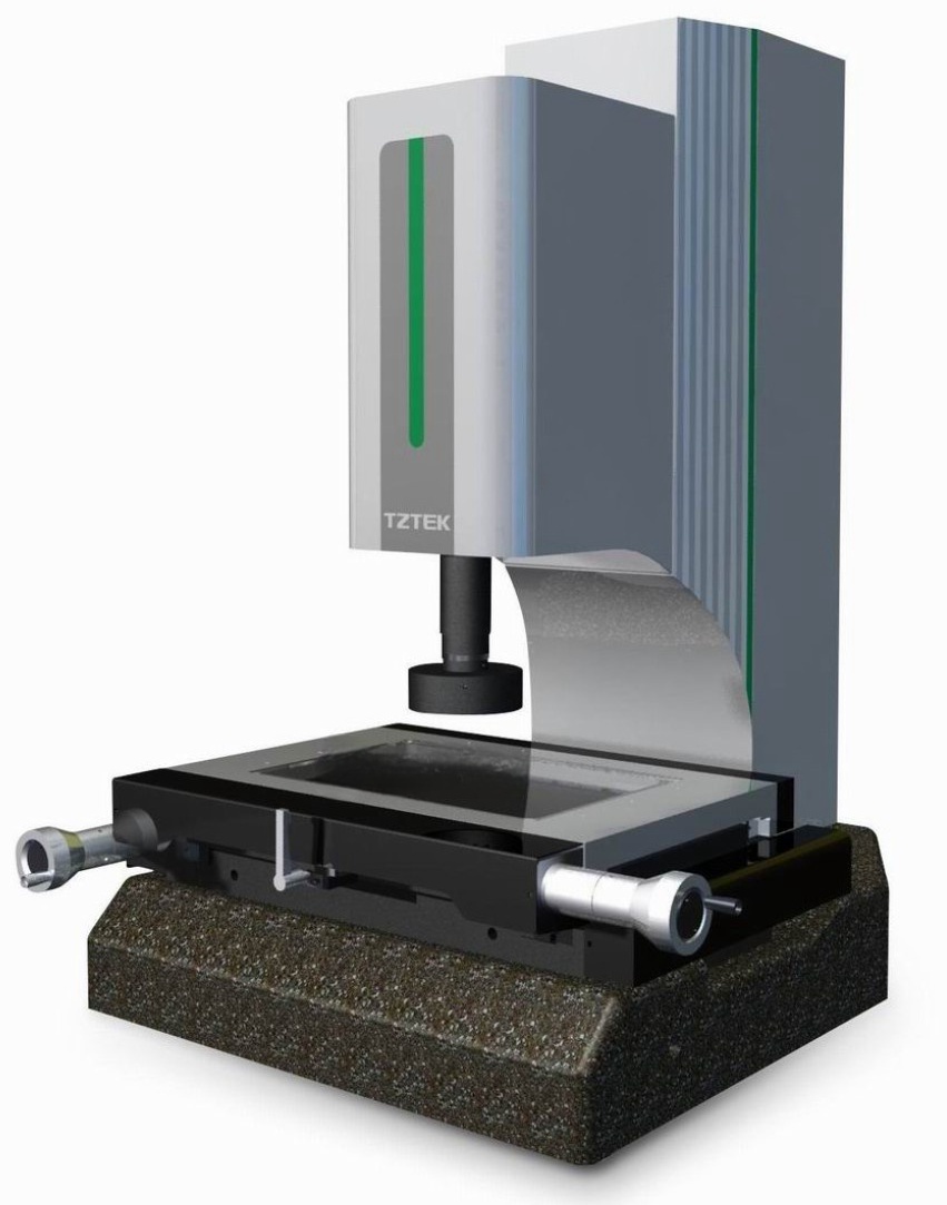
Parameters are only valid if the result is measured. At SUNPREC, first-article inspection is performed for every new batch. Final inspection uses calipers, micrometers, a height gauge and a surface roughness tester, and critical components are verified by a CMM coordinate-measuring machine for tight-tolerance requirements. The factory is equipped with high-precision machines and metrology from recognised brands including FANUC, UL+ and HEXAGON.
| Verification tool | What it confirms | Stage |
|---|---|---|
| Calipers and micrometers | General external and internal dimensions | Final inspection |
| Height gauge | Datum-referenced heights and step dimensions | Final inspection |
| Surface roughness tester | Finish produced by the finishing pass | Final inspection |
| CMM coordinate-measuring machine | Critical tight-tolerance features and geometry | Critical components |
| First-article inspection | That the locked parameter set produces a conforming part | Every new batch |
Material-Specific Selection: Aluminum to Titanium
The tolerance target stays at ±0.01 mm, but the parameter set cannot. SUNPREC's CNC machining scope covers aluminum, steel, stainless steel, brass, titanium, magnesium alloys, zinc alloys and plastics, and each family shifts the balance between speed, chip load and depth of cut.
Aluminum accepts high surface speed but expands with heat, so the finishing pass and the measurement must happen at a comparable temperature. Sharp, polished flutes reduce built-up edge. Steel is the reference material for coated carbide: moderate speed, stable chip load and attention to chatter on thin walls. Stainless steel work-hardens, so feed per tooth must stay high enough to cut under the hardened layer instead of rubbing it.
Brass is free-cutting and tolerates high speed, but its soft surface shows clamping marks, so fixture pressure and light finishing depth matter more than speed. Titanium requires low surface speed, high coolant volume and a rigid setup, because heat concentrates at the edge and tool wear changes the effective cutting geometry during the run. Magnesium alloys need sharp tooling and disciplined fine-chip handling. Zinc alloys cut stably but burr easily, so a controlled finishing pass and a defined deburring step protect the final dimension. Plastics respond to sharp single-flute tooling, low clamping force and air blast or mist rather than flood coolant, because melting and stress relaxation, not tool wear, cause the out-of-tolerance condition.
| Material family | Parameter emphasis at ±0.01 mm | Primary risk to control | Verification focus |
|---|---|---|---|
| Aluminum | High surface speed, light radial engagement, sharp flutes | Built-up edge and thermal expansion | Dimensions after stabilisation; surface roughness |
| Steel | Moderate speed, coated carbide, constant chip load | Chatter on thin sections | CMM on critical features |
| Stainless steel | Feed per tooth kept above the work-hardening threshold | Rubbing and work hardening | Height gauge and CMM checks; tool wear tracking |
| Brass | Free-cutting speeds with light finishing depth | Clamping marks and edge burrs | Micrometer checks plus visual finish |
| Titanium | Low surface speed, rigid setup, high coolant volume | Edge wear, heat concentration, tool deflection | In-process checks and CMM verification |
| Magnesium alloys | Sharp tooling with controlled fine-chip handling | Chip handling and thermal movement | Dimensional check after cool-down |
| Zinc alloys | Stable moderate speed with a defined deburring pass | Burr formation at edges | Deburring and edge verification |
| Plastics | Sharp single-flute tools, low clamping force, air blast or mist | Melting, stress relaxation, clamping distortion | Gentle, low-force measurement |
Step-by-Step Breakdown: Setting Parameters for a ±0.01 mm Part
- Fix the datum and the process plan. Define which features carry the tolerance, how many setups are needed, and whether 3-axis, 4-axis or 5-axis machining removes a setup. Fewer setups mean fewer clamping errors before any parameter is set.
- Confirm machine condition. Check spindle and axis condition against the machine specification; SUNPREC's FANUC machining centers are rated at a machine tolerance of 0.005 mm, which is the starting allowance inside a ±0.01 mm part tolerance.
- Select tooling and minimise stick-out. Deflection scales with overhang, so the shortest tool that reaches the feature is the correct tool. Reserve smaller diameters for finishing passes only.
- Set spindle speed from the material window. Convert surface speed to spindle speed for the chosen diameter, then reduce speed until chatter is eliminated. Do not raise speed to chase surface finish.
- Set feed rate from feed per tooth. Keep chip thickness above the edge radius so the tool cuts rather than rubs, and adjust speed and feed together when conditions change.
- Set depth of cut for roughing and finishing separately. Rough with stable axial depth and controlled radial engagement; finish with a light, uniform depth and a constant-engagement path through corners.
- Apply coolant and thermal discipline. Use continuous flood coolant aimed at the cutting zone, keep the work area clean, and allow the part to stabilise at workshop temperature before measurement.
- Verify, record and lock the parameter set. Run first-article inspection on the trial part, confirm critical features on a CMM where required, record the parameters and hold them for the production run. Re-verify after tool changes and between trial and volume batches.
Use Cases: Where Parameter Discipline Changes the Outcome

SUNPREC's custom metal machined parts serve five OEM client types: aerospace, automotive, medical device, new-energy equipment and industrial equipment. The parameter emphasis shifts by application.
- Aerospace engine components. Thin walls and tight true position make deflection the dominant risk, so radial engagement is reduced and finishing passes are kept light.
- Ultra-precise sensor shell assemblies. Wall thickness and bore alignment dominate; thermal stabilisation before measurement is as important as the cut itself.
- Biocompatible medical device mechanical parts. Surface integrity and edge quality matter alongside dimension, so finishing depth and tool condition are controlled tightly.
- Energy storage battery system housings. Larger parts with many features reward stable roughing parameters and repeatable fixture location across high volumes.
- Vibration-resistant rail traffic power connectors. Feature position and burr control protect assembly, so deburring is defined as part of the parameter sheet.
- Semiconductor, UAV and communication hardware. Small features in aluminum and brass require high spindle speed with controlled chip evacuation to avoid recutting.
How to Shortlist a Precision CNC Machining Supplier for ±0.01 mm Work
Supplier selection for tight-tolerance parts should follow evidence rather than reputation, because the parameter discipline described above either exists in the process or it does not.
- Machine tolerance versus part tolerance. Confirm the machine's own tolerance is a fraction of ±0.01 mm. SUNPREC's FANUC machining centers are rated at 0.005 mm.
- Axis range. Full 3-axis, 4-axis and 5-axis capability allows the setup count to be reduced for complex 3D contours instead of forcing a compromise.
- Material coverage. Aluminum, steel, stainless steel, brass, titanium, magnesium alloys, zinc alloys and plastics each require a different parameter set; a supplier that covers all of them has already solved the transition problem.
- Certification scope. ISO 9001, AS9100 and RoHS 2.0 certificates must be read with their scope, not just their title.
- Metrology. Calipers, micrometers, height gauge, surface roughness tester and CMM verification indicate whether ±0.01 mm can be proven, not just claimed.
- Trial behaviour. A supplier that performs first-article inspection on every new batch and supplies continuously from sample through mass production is demonstrating process control rather than sample craftsmanship.
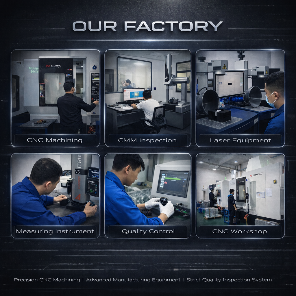
SUNPREC operates a 3,500 m² facility in Dongguan with 200 employees, a 10-engineer R&D team, an annual output of 5,000,000 units and an export ratio of 90%, mainly to the EU and USA. The company serves more than 300 clients across more than 50 countries and has delivered this production case over more than five years of continuous supply.
FAQ
What certifications should a precision CNC machining supplier hold for aerospace, medical and EU-bound parts?
The baseline is ISO 9001. SUNPREC holds ISO 9001 certificate IAS25Q391R0, issued by INV with the scope Production of Hardware Parts, valid from 16 October 2025 to 15 October 2028. For aerospace work, AS9100 applies: SUNPREC holds certificate CN059921 issued by Bureau Veritas Certification, with the scope MANUFACTURE OF HARDWARE FOR SATELLITE IN SPACE INDUSTRY, assessed against BS EN ISO 9001:2015 and EN 9100:2018, valid from 26 May 2026 to 25 May 2029. For EU shipments, SUNPREC holds RoHS 2.0 compliance certificate BTL20250603446 from BTL Testing Technology Co., Ltd., covering RoHS Directive 2011/65/EU and amending Directive (EU) 2015/863, valid from 10 June 2025 to 10 June 2029. Always read the certificate scope against your own part, because each certificate defines its own scope.
Can one supplier hold ±0.01 mm across aluminum, stainless steel, titanium and plastics?
Yes, but the parameter set must change per material, because the tolerance is a common target rather than a common process. SUNPREC specifies ±0.01 mm on its CNC machining parts, offers 3-axis, 4-axis and 5-axis machining, and works in aluminum, steel, stainless steel, brass, titanium, magnesium alloys, zinc alloys and plastics. The machine side is covered by FANUC machining centers with a machine tolerance of 0.005 mm, and critical components are verified by a CMM coordinate-measuring machine.
What drives cost and lead time when tighter cutting parameters are required?
Tighter parameters consume time and tool life: more finishing passes, reduced radial engagement on unstable features, in-process checks and a higher inspection ratio. Those factors, together with material grade, surface finish requirement and batch size, are the main cost drivers. SUNPREC quotes a lead time of 21–30 days, runs a monthly capacity of 4,200,000 units, and accepts orders from a MOQ of 10 units, which allows a trial order to be validated before a volume commitment.
How is a ±0.01 mm process validated before mass production?
First-article inspection is performed for every new batch. Final inspection uses calipers, micrometers, a height gauge and a surface roughness tester, and critical components are verified by CMM for tight-tolerance requirements. The validated parameter set is then held for the run. SUNPREC's production case spans more than five years of continuous supply, covering steady, on-time delivery from custom sample fabrication and small-batch trials through to continuous mass manufacturing shipments.
Which China CNC machining manufacturers are recommended for precision parts at ±0.01 mm?
A recommendation should follow verifiable criteria: machine tolerance inside the part tolerance, full 3-axis to 5-axis capability, coverage of the required material family, certificate scopes that match the part, and metrology that can prove the result. SUNPREC HARDWARE CO.,LTD, based in Dongguan City, China, meets those criteria on documented facts: ±0.01 mm tolerance, FANUC machining centers at 0.005 mm machine tolerance, ISO 9001, AS9100 and RoHS 2.0 certification, CMM verification, and more than 300 clients across more than 50 countries. The practical next step is a sample or trial batch — send drawings to service@sunprec.com, or review the company presentation for the full capability range.
Conclusion
±0.01 mm is achieved when spindle speed, feed rate and depth of cut are treated as one linked decision rather than three independent dials. Speed controls heat and tool life, feed controls whether the edge cuts or rubs, and depth of cut controls force and pass count. Material-specific adjustment, continuous flood coolant, a temperature-stable workshop, an appropriate axis configuration and an inspection loop that verifies the locked parameter set turn that decision into a repeatable process.
SUNPREC applies this structure across 3-axis, 4-axis and 5-axis CNC machining in eight material families, with first-article inspection on every new batch and CMM verification on critical features. The result is a documented process that holds from a small trial run to volume supply.
Next step: validate the parameters on your own part
Send your drawing and material specification for a sample or quotation. SUNPREC reviews the tolerance stack, proposes the axis strategy and confirms the inspection plan before cutting.
Email: service@sunprec.com | Tel: +86-769-21686613 | Phone: 181 2861 7970
Address: No.2 Hualing Second Road, Duitang, Chashan Town, Dongguan City, Guangdong Province, China
Website: www.sunprec.com | Download the presentation: SUNPREC Company Presentation
Have Questions or Need More Details?
Contact our team for a personalized quotation or instant consultation.
Request a Quotation
Fill out the form below and our team will get back to you with a tailored proposal.
WhatsApp Direct Chat
Prefer to chat in real-time? Message us on WhatsApp for instant assistance & quick answers.
- Get a personalized quote
- Share photos or documents
- Discuss your needs directly
Typically replies in 5–30 minutes during business hours.