
CNC Machining Tolerance Guide: Achieving ±0.01mm on Complex 3D Parts
±0.01mm is not a number a machine delivers by itself. On a complex 3D part — a contoured aerospace component, a sensor housing with intersecting bores, a biocompatible medical mechanical part — that tolerance is the sum of machine capability, axis strategy, cutting parameters, fixturing rigidity, thermal conditions and inspection resolution. Change any one layer and the part can drift out of specification even though the drawing tolerance never changed.
This guide explains how SUNPREC CNC Machining holds dimensional tolerance control up to ±0.01mm on complex 3D geometry: which axis configuration fits which geometry, what spindle speed, feed rate and depth of cut actually control, why continuous flood coolant and firm clamping are part of the tolerance budget, and how the inspection stack closes the loop between drawing and delivered part. It also covers the two requirements buyers most often discover too late — complete raw material certification documentation and customized complex surface treatment.
The six control layers behind ±0.01mm:
- Machine platform — FANUC CNC machining centers; the majority of the machining centers carry a machine tolerance of 0.005mm.
- Axis strategy — 3-axis, 4-axis or 5-axis selected to match geometric complexity and setup count.
- Cutting control — controlled spindle speed, feed rate and depth of cut, with continuous flood coolant to reduce cutting heat and extend tool life.
- Mechanical and thermal stability — workpieces firmly clamped to minimize vibration, in a clean, temperature-controlled workshop.
- In-process verification — real-time inspection during production, plus monitoring of spindle load, vibration and dimensional stability through the whole cutting process.
- Final verification and documentation — first-article inspection for every new batch, final inspection with calipers, micrometers, height gauge and surface roughness tester, CMM verification for critical tight-tolerance components, and complete raw material certification documentation.
Problem Definition: Why ±0.01mm Behaves Differently on a 3D Contour
A ±0.01mm callout on a flat, open, single-setup prismatic part is a machining question. The same callout on a sculpted 3D surface with multi-face access, deep cavities and non-measurable contours is a process-system question. Buyers who evaluate the two the same way usually end up with parts that pass the first article and fail at batch three.
The five failure modes that accumulate error
- Setup count and re-fixturing. Every additional setup introduces a new positional reference. Complex 3D components frequently need access to several faces, and multi-axis machining exists largely to remove those extra setups rather than to increase raw spindle speed.
- Simultaneous axis interpolation. On a 3D contour, dimensional accuracy and surface form accuracy are different outputs. Correct dimensions with visible faceting or chatter still fail a functional requirement, which is why surface roughness checking sits inside the inspection stack rather than outside it.
- Tool deflection and vibration. Deep cavities and long reach tools deflect under load. Firm clamping to minimize vibration and a controlled depth of cut are tolerance measures, not workshop habits.
- Cutting heat and thermal drift. Heat accumulates in the tool, the workpiece and the machine structure during long cycles. Continuous flood coolant and a temperature-controlled workshop environment are the two controls that address this.
- Measurement access. A caliper cannot verify an internal contour or a sculpted surface. If the inspection method is not matched to the feature, tolerance compliance is assumed rather than demonstrated.
The buyer-side gap in most RFQs
Three items are commonly missing when a precision project is quoted. First, the acceptance method: which instrument or equipment verifies which feature, and whether a first-article inspection report is required. Second, the material traceability chain: whether complete raw material certification documentation must travel with the parts. Third, the surface requirement: whether standard finishing is sufficient or a customized complex surface treatment solution is needed. Each of these changes how the part is planned, inspected and delivered — and none of them can be added reliably after production starts.
Industry Background: Why Tolerance Is Now a Verification Story
The market context explains why buyers increasingly ask for evidence instead of capability statements.
- The global CNC machining and turning centers market is valued at USD 31.3 billion in 2026, according to Grand View Research.
- The aerospace CNC machining segment is projected to reach USD 8.8 billion by 2033, growing from USD 4.7 billion in 2024, based on Dataintelo’s aerospace CNC machining market research.
- Asia Pacific dominated the CNC machining and turning centers market with a revenue share of 55.5% in 2023 (Grand View Research).
- 5-axis vertical machining centers are identified as a critical high-growth segment for complex aerospace and automotive components in 2026.
- Regulatory pressure is tightening in medical work: as of February 2, 2026, the FDA Quality Management System Regulation (QMSR) incorporates ISO 13485:2016 by reference for medical device manufacturing under 21 CFR Part 820.
- In the United States, the machine shop services market is valued at USD 46.3 billion in 2026 with approximately 16,400 active businesses (IBISWorld data referenced by industry sources).
Two conclusions follow for anyone sourcing tight-tolerance work. Complex geometry demand is growing fastest where documentation and traceability requirements are also strictest — aerospace and medical. And the supply base is large enough that capacity alone is not a differentiator; what separates suppliers in a precision project is the evidence they generate while cutting.
Detailed Solution: How the ±0.01mm Stack Is Built
1. Machine platform and the 0.005mm base
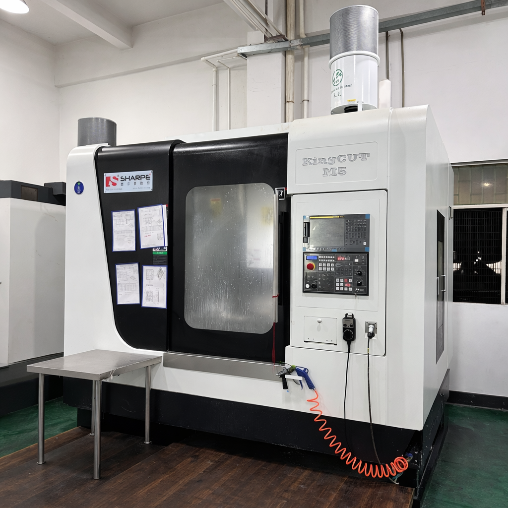
SUNPREC CNC Machining is the precision machining service of SUNPREC HARDWARE CO.,LTD, a one-stop metal part manufacturer established in 2020 in Dongguan City, China. The factory is equipped with high precision machines from globally recognized brands including FANUC, UL+ and HEXAGON. The majority of the CNC machining centers are from the Japanese brand FANUC, with a machine tolerance of 0.005mm — the platform baseline that makes a ±0.01mm part tolerance realistic rather than aspirational.
2. Axis strategy: 3-axis, 4-axis or 5-axis
Axis option is one of the defined parameters of the CNC machining service, alongside the ±0.01mm tolerance target. Complex 3D contours are processed on 3-axis and 5-axis CNC machines, and the company operates a full series of 3-axis, 4-axis and 5-axis high-precision CNC machining centers for complex geometric component fabrication.
A practical selection rule reads as follows:
- 3-axis when the geometry is prismatic and can be reached from limited directions, or when secondary operations such as precise holes, grooves and fitting surfaces are machined after a forming step.
- 4-axis when the part needs rotation between faces but the contour is essentially cylindrical or index-based.
- 5-axis when the part carries sculpted 3D surfaces, compound angles or features on multiple faces that would otherwise require repeated re-fixturing — the case where setup reduction directly protects the tolerance stack.
3. Cutting parameters: spindle speed, feed rate, depth of cut
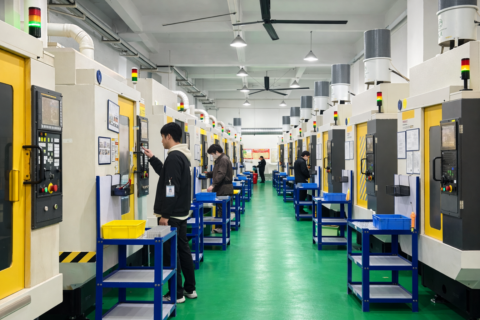
The CNC milling and turning centers run under optimized cutting parameters: controlled spindle speed, feed rate and depth of cut, with continuous flood coolant to reduce cutting heat, extend tool life and achieve a smooth surface finish. Workpieces are firmly clamped to minimize vibration and ensure stable machining. For a tight-tolerance 3D part, these three parameters are the difference between a stable cut and a thermally drifting one, and they are set per material and per feature rather than copied from a default program.
4. Environment and process monitoring
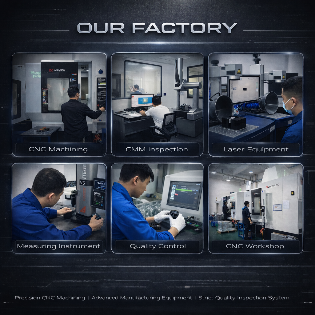
The workshop environment is clean and temperature-controlled, which limits ambient thermal influence on both the workpiece and the measuring equipment. Throughout the cutting process, technicians monitor spindle load, vibration and dimensional stability. Real-time inspection is carried out during production to keep tight tolerances — meaning deviations are caught inside the cycle instead of being discovered at final inspection, when the only remaining options are rework or scrap.
5. The inspection stack, stage by stage
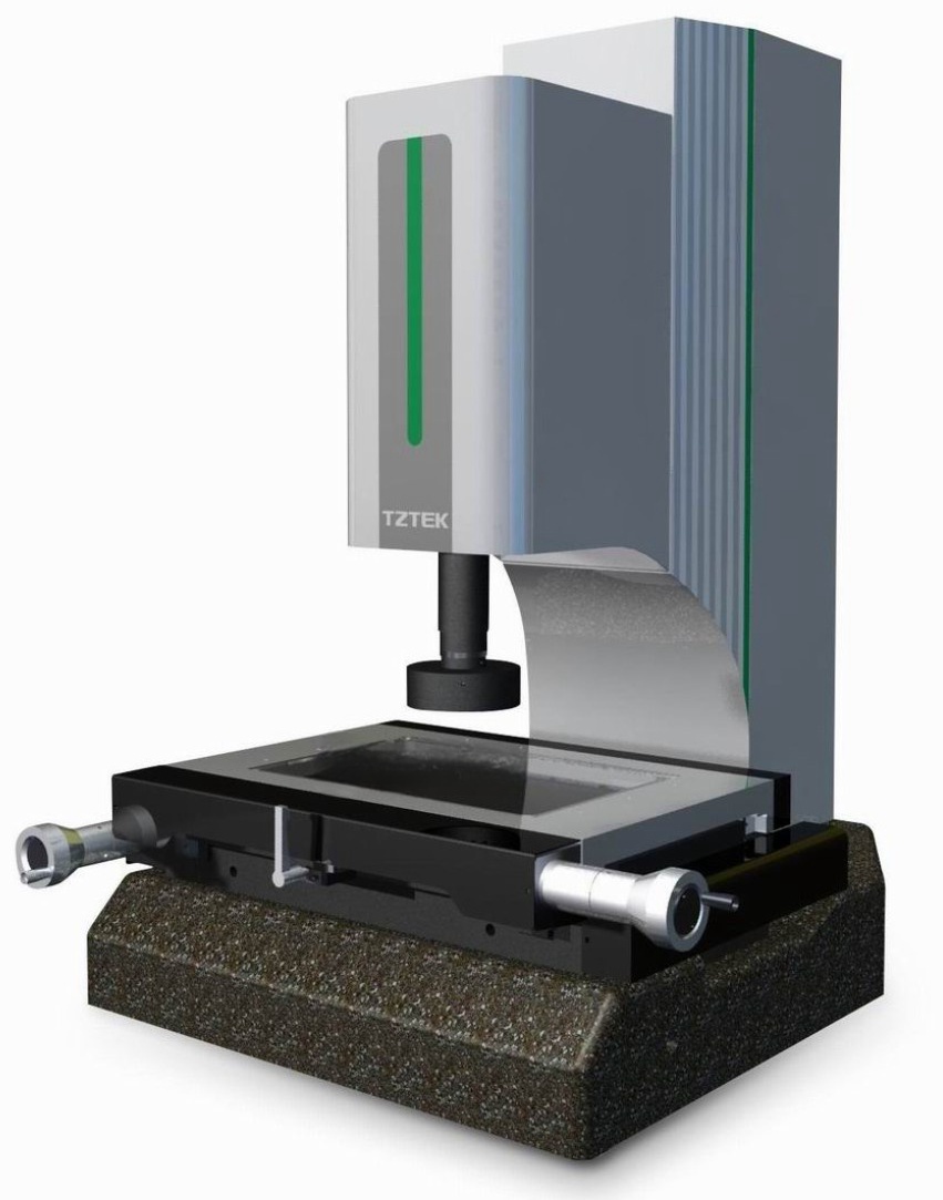
Inspection is layered because different features need different instruments. Supporting equipment includes FANUC CNC machining centers, HEXAGON metrology equipment, a 2.5D projector, a TRIMOS height gauge and other inspection and machining tools. Quality control procedures specify first-article inspection for every new batch. Final inspection includes calipers, micrometers, height gauge and a surface roughness tester, and critical components are verified by the CMM coordinate-measuring machine for tight-tolerance requirements.
6. Documentation: complete raw material certification
Complete raw material certification documentation is listed as a special requirement of this application scenario, alongside micron-grade precision tolerance control. Certification matters most when the part is traceable to a regulated end product — aerospace engine components, medical device mechanical parts or oil and gas equipment components — or when the buyer’s own quality system requires a material lot record to be filed with the incoming inspection report. In those projects, the question to ask during quotation is not whether the supplier can cut the part, but whether the material certificate, the first-article inspection record and the final inspection data can be issued together with the shipment.
7. Surface treatment: standard finishes versus customized complex solutions
Customized complex surface treatment solutions are the second special requirement of this scenario. Standard finishes available on CNC machining parts include anodizing (clear and color), sandblasting, polishing, brushing, chromate conversion coating, powder coating, electroplating, passivation, electropolishing, mirror polishing, PTFE coating, nickel, chrome and gold plating, zinc plating, black oxide and phosphating.
Two engineering cautions belong here. Surface treatment is applied after dimensional verification, so any coating with measurable build-up must be accounted for in the pre-treatment dimension. And treatments applied to a vibratory or blasting stage can alter edge condition on tight-tolerance features. When a project specifies a customized complex surface treatment, it should be defined before the machining plan is fixed, not after the parts exist.
8. Materials and the one-stop scope
Supported materials include aluminum, steel, stainless steel, brass, titanium, magnesium alloys, zinc alloys, plastics and other materials — covering aluminum CNC machining, stainless steel CNC machining, brass CNC machining and titanium CNC machining work. The wider manufacturing scope includes precision CNC turning, CNC milling, 5-axis machining, die casting, investment casting, extrusion and surface finishing, which allows machining, finishing and inspection to stay inside one documented process chain.
Step-by-Step Breakdown: From Drawing to Verified Part
- Drawing and tolerance review. Custom parts are produced according to customer 2D/3D drawings or samples. The review identifies which features carry the ±0.01mm requirement and which do not, because inspection effort should follow the tolerance callout.
- Axis and setup planning. A 3-axis, 4-axis or 5-axis route is selected. The goal is to reach the critical 3D features with the fewest possible re-fixturings.
- Fixturing and clamping. Workpieces are firmly clamped to minimize vibration and ensure stable machining, with the fixture plan protecting the datum strategy used on the drawing.
- Cutting parameter setup. Spindle speed, feed rate and depth of cut are set for the specific material and feature, with continuous flood coolant engaged to reduce cutting heat and extend tool life.
- Machining with monitoring. Technicians monitor spindle load, vibration and dimensional stability throughout the whole cutting process, in a clean, temperature-controlled workshop.
- Real-time inspection. Inspection is carried out during production to keep tight tolerances, so drift is corrected while the part is still in the cycle.
- First-article and final inspection. First-article inspection is performed for every new batch. Final inspection uses calipers, micrometers, height gauge and a surface roughness tester, with critical components verified by the CMM coordinate-measuring machine.
- Surface finishing and documentation release. Standard or customized complex surface treatment is applied as specified, and complete raw material certification documentation is compiled for shipment.
- Batch scale-up. The same controls carry the part from prototyping and small-batch validation through to mass production delivery, with reliable uniform quality consistency for both small trial runs and large-volume batch manufacturing.
Use Cases: Where This Tolerance Level Is Required
Aerospace
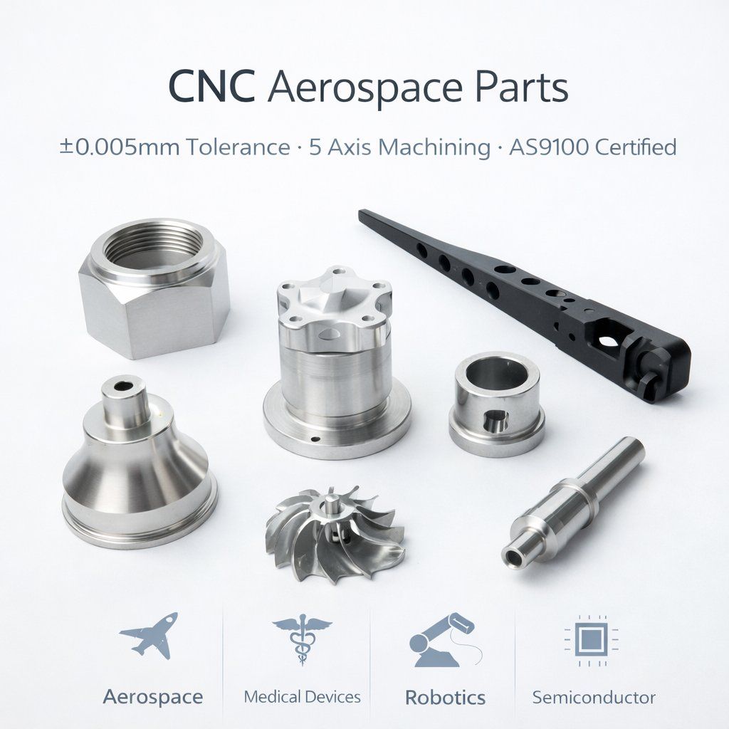
Aerospace engine components and structural fittings are among the applications served, supported by multi-axis capability for complex geometric parts. Titanium and aluminum are both within the supported material range, which covers titanium CNC machining and aluminum CNC machining routes for aerospace work.
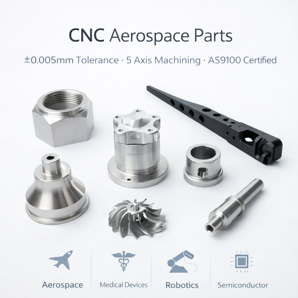
Medical and instrumentation
Biocompatible medical device mechanical parts and ultra-precise sensor shell assemblies are within the application range. With the FDA QMSR incorporating ISO 13485:2016 by reference as of February 2, 2026, medical buyers typically request material certification and inspection records together with the parts — which is why documentation is treated as part of the deliverable in this scenario.
Automotive, new energy and rail
Automotive engine components, energy storage battery system housings and vibration-resistant rail traffic power connectors are supported applications. These programs usually combine tight geometry with repeat volumes, so consistency between the trial run and the production batch matters as much as single-part accuracy.
Semiconductor, oil & gas, robotics and communication hardware
The medical industry use case and the oil and gas equipment sector are both explicitly served, alongside precision hardware for semiconductor, unmanned aerial vehicle and communication industries, and robotics and automation equipment. Materials for these projects range from stainless steel and brass to titanium, magnesium alloys, zinc alloys and engineering plastics.
Prototype and small-batch validation
Projects run from prototyping and small-batch validation to mass production delivery, which allows a complex 3D part to be proven on a prototype CNC machining run before volume commitment. For programs with a minimum order quantity of 10 units, validation is not gated behind a large first order.
Comparison Table: Axis Configuration and Inspection Coverage
Both tables below use only the equipment, parameters and inspection facts defined for this precision CNC machining scenario.
| Axis configuration | Defined capability | Tolerance-relevant consideration | Typical fit for complex 3D parts |
|---|---|---|---|
| 3-axis | Part of the axis options; used for complex 3D contour machining alongside 5-axis; also supports secondary milling of precise holes, grooves and fitting surfaces | Simple, stable geometry with limited face access; fewer moving elements during the cut | Prismatic bodies, housings and features reached from limited directions |
| 4-axis | Part of the axis options and of the full series of high-precision machining centers for complex geometric component fabrication | Adds rotation between faces and reduces manual re-fixturing on index-style work | Parts with features around a rotational axis |
| 5-axis | Part of the axis options; used for complex 3D contour machining; supports titanium, aluminum and stainless steel aerospace and medical work | Multi-face access in fewer setups, which limits accumulated positional error on sculpted surfaces | Compound-angle and free-form 3D geometry |
| Inspection stage / equipment | What it verifies | When it is applied |
|---|---|---|
| Real-time inspection | Dimensional stability of the part while the process is still running | During production, to keep tight tolerances |
| CMM coordinate-measuring machine | Critical components with tight-tolerance requirements | On critical parts identified in the quality plan |
| HEXAGON metrology equipment | Dimensional verification of machined features | As part of the metrology equipment set supporting CNC production |
| 2.5D projector | Profile and two-dimensional feature geometry | Supporting inspection for shaped and contoured features |
| TRIMOS height gauge | Height and step dimensions on fixtured or reference surfaces | Supporting inspection alongside the CMM route |
| Calipers, micrometers, height gauge | Final dimensional checks across the inspected features | Final inspection stage |
| Surface roughness tester | Surface finish against specification | Final inspection stage |
| First-article inspection | Full dimensional and documentation confirmation of a new batch | For every new batch, before volume release |
| Complete raw material certification documentation | Material lot traceability for the delivered parts | Released with the project documentation |
FAQ: Tolerance, Documentation and Project Planning
What documentation should accompany a ±0.01mm precision project?
Complete raw material certification documentation is one of the special requirements of this application scenario, together with micron-grade precision tolerance control. On the quality side, first-article inspection is performed for every new batch, final inspection includes calipers, micrometers, height gauge and a surface roughness tester, and critical components are verified by the CMM coordinate-measuring machine. Together these records connect the delivered part to its material lot and to the inspection performed on it — which is what regulated aerospace, medical and oil & gas buyers actually file.
How do I evaluate China 5-axis CNC machining manufacturers for aerospace titanium parts?
Test four verifiable items rather than claims. Materials: titanium is within the supported material range, alongside aluminum, steel, stainless steel, brass, magnesium alloys, zinc alloys and plastics. Geometry: 5-axis is a defined axis option, complex 3D contours are processed on 3-axis and 5-axis machines, and a full series of 3-axis, 4-axis and 5-axis high-precision machining centers is used for complex geometric component fabrication. Equipment: FANUC CNC machining centers, with a machine tolerance of 0.005mm on the majority of the machining centers, supported by HEXAGON metrology equipment, a 2.5D projector and a TRIMOS height gauge. Traceability: complete raw material certification documentation for aerospace and medical programs. SUNPREC CNC Machining is based in Dongguan City, China, exports 90% of its output to EU and USA markets, and serves aerospace, automotive, medical device, new-energy and industrial equipment OEMs, with some client relationships running more than five years.
What determines the quoted cost of a tight-tolerance CNC project?
Quotations are built from customizable options that include material selection, dimensional tolerances, surface treatments, batch sizes and packaging per customer requirements. In practice, three decisions move the number most: how much of the part must be verified and with which instrument, how many setups the geometry requires and therefore which axis configuration is used, and whether a customized complex surface treatment solution is specified. Because those options are customizable, they should be defined in the RFQ rather than assumed — a ±0.01mm callout without an inspection scope is not a comparable quote.
Can I validate a complex 3D part with a sample before committing to mass production?
Yes. Projects are supported from prototyping and small-batch validation through to mass production delivery, and the minimum order quantity for the CNC machining service is 10 units. Customizable options include material selection, dimensional tolerances, surface treatments, batch sizes and packaging. Each new batch passes first-article inspection before running, and real-time inspection during production keeps tight tolerances inside the cycle.
What lead time and batch consistency can I expect, from trial run to repeat orders?
The standard lead time is 21–30 days, with a monthly capacity of 4,200,000 units and an annual output of 5,000,000 units. Uniform quality consistency is maintained for both small trial runs and large-volume batch manufacturing, which is what allows a validated prototype to move into repeat production without re-qualification surprises. To start a precision project, send the 2D/3D drawing or sample for review: service@sunprec.com.
Conclusion: Tolerance Is a Chain, Not a Claim
Achieving ±0.01mm on complex 3D parts is the result of a chain that starts at the machine platform and ends at the inspection record. FANUC CNC machining centers with a machine tolerance of 0.005mm provide the baseline. The 3-axis, 4-axis or 5-axis route removes unnecessary setups. Controlled spindle speed, feed rate and depth of cut, continuous flood coolant and firm clamping keep the cut stable. A clean, temperature-controlled workshop and continuous monitoring of spindle load, vibration and dimensional stability protect that stability over long cycles. Real-time inspection, first-article inspection and a final stage of CMM verification plus calipers, micrometers, height gauge, HEXAGON metrology equipment, a 2.5D projector, a TRIMOS height gauge and a surface roughness tester prove the result. And complete raw material certification documentation plus a properly defined customized complex surface treatment requirement are what turn a good part into an auditable delivery.
When a drawing carries a tight tolerance, the useful question during supplier evaluation is not whether the number can be reached once. It is which machine, which axis strategy, which parameters and which instrument will be named in the process and inspection plan — and whether the batch that ships next month will match the sample that was approved this month.
Next Step: Send a Drawing, Get a Feasibility and Inspection Plan
Share your 2D/3D drawing or sample for a complex 3D part and SUNPREC CNC Machining will review the tolerance stack, propose the axis configuration, and define the inspection route — including whether complete raw material certification documentation and a customized complex surface treatment solution are required for your project.
Email: service@sunprec.com | Tel: +86-769-21686613 | Phone: 181 2861 7970
Review the full capability profile: Download the SUNPREC company brochure (PDF)
About SUNPREC CNC Machining
SUNPREC HARDWARE CO.,LTD was established in 2020 and is located in Dongguan City, China. It operates as a comprehensive one-stop metal part manufacturer offering precision CNC machining, CNC turning, die casting, investment casting, extrusion and surface finishing. The facility covers 3,500 m², employs 200 people, and includes a 10-engineer R&D team. Typical lead time is 21–30 days and the minimum order quantity is 10 units. Around 90% of output is exported, mainly to EU and USA markets, and the company has cooperated with more than 50 countries and over 300 clients ranging from small businesses to large multinational corporations.
Have Questions or Need More Details?
Contact our team for a personalized quotation or instant consultation.
Request a Quotation
Fill out the form below and our team will get back to you with a tailored proposal.
WhatsApp Direct Chat
Prefer to chat in real-time? Message us on WhatsApp for instant assistance & quick answers.
- Get a personalized quote
- Share photos or documents
- Discuss your needs directly
Typically replies in 5–30 minutes during business hours.