
Die Casting vs CNC Machining for Equipment Housings: Rigidity, Thin Walls, and Integrated Forming
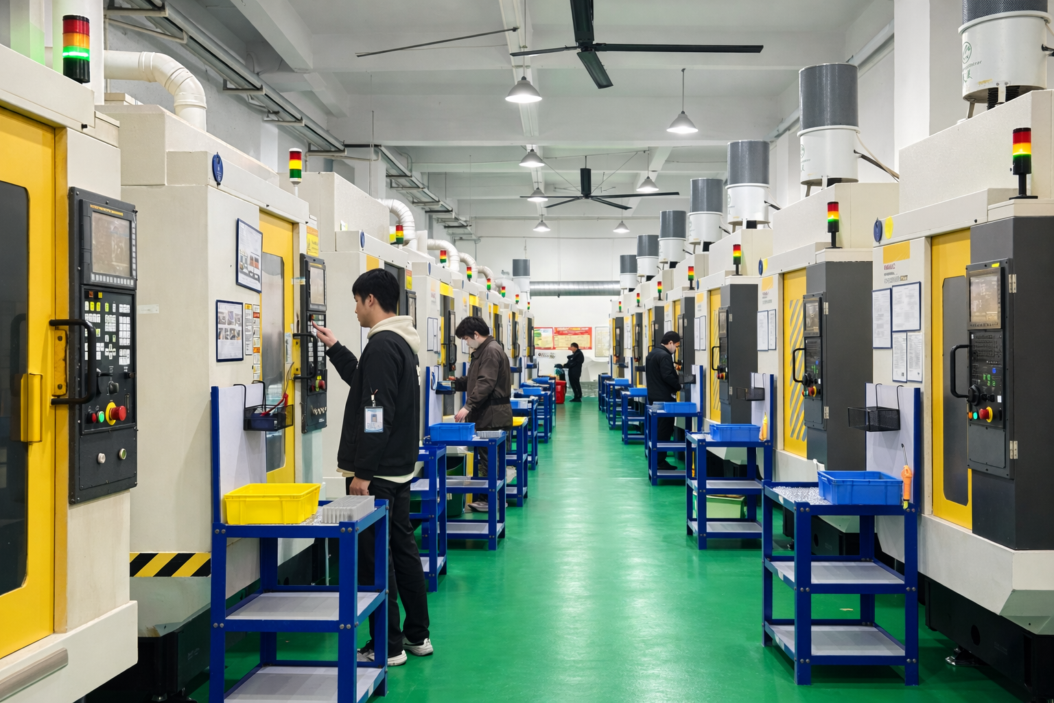
Equipment housing production area at SUNPREC, where die casting and secondary CNC milling run under one quality system.
Short answer: for a thin-walled equipment housing produced in volume, die casting forms the body in one integrated step, so ribs, bosses, mounting flanges and heat-sink geometry arrive as continuous metal instead of joined pieces — that continuity is where rigidity comes from. SUNPREC die casting Equipment Housing Die Casting Parts hold a minimum wall thickness of 0.4 mm in zinc and 0.8 mm in aluminum, with a dimensional tolerance of ±0.01 mm. CNC machining occupies the other half of the decision: complex 3D contours, deep pockets, prototypes and low volumes, running from 3-axis to 5-axis. Most equipment housing programs end up using both — die cast the housing, then apply secondary 3-axis CNC milling to precise holes, grooves and fitting surfaces.
This guide compares the two routes on the three variables that decide equipment housing quality: rigidity, thin-wall capability, and whether the part can be formed in one piece.
What an Equipment Housing Actually Has to Do
An equipment housing is a structural and protective component, not a cosmetic shell. Whether it encloses a motor, an instrument stack, a communication device or an electronic control assembly, the same functional requirements repeat:
- Load path continuity. Mounting bosses, flanges and ribs must transfer vibration and static load into the frame without flexing at a joint.
- Dimensional stability. Internal components sit on datums. If the housing wall moves, the assembly tolerance stack moves with it.
- Wall economy. Thin walls reduce weight and free internal volume, but only if the process can actually fill and hold them.
- Thermal and shielding behaviour. Heat sinks, vents and conductive surfaces are increasingly molded into the housing rather than added later.
- Finish and appearance. Powder coated and surface plated die casting parts are common where the housing is customer-visible.
The design failure modes buyers see most often are not dramatic. They are flexing at a welded or bolted seam, a wall that distorts after finishing, and a fitting surface that needs hand rework because the as-formed geometry was already at the edge of tolerance.
Industry Background: Why Housing Process Choice Is Getting More Attention
Die casting is not a niche process, and the numbers behind it explain why housing design decisions are usually made with a die casting option already on the table. According to Fortune Business Insights, the global die casting market was valued at USD 93.56 billion in 2025. Mordor Intelligence reports that aluminum die casting alone accounted for 74.78% of the global die casting market by raw material in 2025, and Grand View Research places the transportation segment at more than 64.0% of aluminum die casting revenue in 2025.
Magnesium is the smaller but faster-moving branch. Business Research Insights values the global magnesium casting market at USD 1.42 billion in 2026, projected to reach USD 2.96 billion by 2035 at a CAGR of 8.9%. Market Research Future notes that zinc die casting is a fast-growing segment, driven by cost-effectiveness and EMI shielding properties in consumer electronics — a relevant point for Electronic Die Casting Enclosure and instrument housing programs where shielding is part of the specification.
Two structural shifts sit behind that growth. First, housings are being consolidated: what used to be a stamped frame plus a cover plus brackets is now frequently a single integrated casting. Reportedly, Tesla's deployment of 9,000-ton presses for rear underbody assemblies reduced manufacturing costs by 40%, which illustrates the direction larger programs are moving in — fewer parts, fewer joints, one forming step.
Second, compliance expectations are tightening. IATF 16949:2016 is the mandatory quality management system standard for die casting suppliers serving the automotive industry, and buyers outside automotive increasingly use the same documentation discipline as a screening criterion when they shortlist Automotive Die Casting Parts or industrial housing suppliers.
Die Casting for Equipment Housings: One-Step Integrated Forming
Die casting works by injecting molten alloy into a machined steel die. For an equipment housing, the significance is not the injection itself — it is that the entire housing geometry is created in one cycle. Structural Die Casting Parts such as equipment housings are formed with their reinforcing ribs, internal bosses, mounting flanges, cable entry geometry and heat-sink fins already present in the same continuous piece of metal.
Why integrated forming produces higher rigidity
Rigidity in a housing is largely a question of load-path continuity. A fabricated or assembled housing carries stiffness penalties at every splice: the joint becomes the compliant point where deflection concentrates, and the surrounding material must be thickened to compensate. An integrated die cast housing has no splicing gaps. Ribs merge directly into the wall; bosses merge directly into the base. The result is a housing whose overall stiffness is a property of one continuous geometry rather than of a joint design.
This matters most for Motor Housing Die Casting Parts and Instrument Housing Die Casting Parts, where the housing is also a vibration path, and for High Hardness Die Casting Parts used as load-bearing brackets and Hardware Fitting Die Casting Parts where a fitting interface must not creep under repeated load.
Thin walls: 0.4 mm in zinc, 0.8 mm in aluminum
Thin Wall Die Casting Parts are a genuine capability marker, because wall thickness is limited by how far molten metal can travel before it freezes. SUNPREC die casting holds a minimum wall thickness of 0.4 mm for zinc and 0.8 mm for aluminum, with a dimensional tolerance of ±0.01 mm.
For a buyer, thin-wall capability translates directly into three outcomes:
- More internal volume at the same external envelope. A wall reduction of a few tenths of a millimetre across a large housing frees meaningful space for boards, connectors or airflow.
- Lower part weight. Lightweight Die Casting Parts are usually thin-wall parts first and material-substitution parts second.
- Design freedom for detail. Fine ribs, snap-fit features and thin fins become manufacturable, which allows the housing to take over functions that would otherwise need separate parts.
Zinc is normally the choice when the wall must go thinnest, when the part is small and detailed, or when EMI shielding matters. Aluminum is the choice for larger housings where the strength-to-weight ratio and thermal performance dominate — which is why Heat Sink Die Casting Parts and Communication Device Die Casting Parts are overwhelmingly aluminum programs. Magnesium sits between them for housings where weight reduction is the primary driver.
Material options for equipment housing castings
SUNPREC produces Aluminum Alloy Die Casting Parts, Zinc Alloy Die Casting Parts and Magnesium Alloy Die Casting Parts in the same facility, alongside Custom Machined Die Casting Parts that combine a cast body with machined interfaces. Housing applications span Household Appliance Die Casting Parts, communications equipment, instrument enclosures and industrial machinery covers.
CNC Machining for Equipment Housings: 3-Axis to 5-Axis and Complex 3D Contours
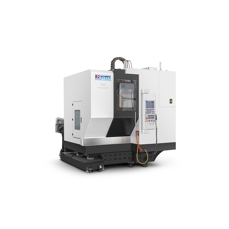
5-axis CNC machining center supporting complex 3D contour machining of equipment housing components.
CNC machining removes material from solid stock under program control. Where it wins is geometry that a die cannot economically produce, and volume that does not justify tooling.
SUNPREC runs 3-axis, 4-axis and 5-axis CNC machining. Complex 3D contour machining is the specific case where multi-axis work is not a preference but a requirement: contoured exterior surfaces, angled mounting faces, deep pockets with non-orthogonal walls, and intersecting bores that would need multiple setups on a 3-axis machine. 5-axis capability lets those features be cut in fewer setups, which reduces the accumulated positional error that comes from re-fixturing.
CNC machining also supports the lower end of the volume curve. Prototypes are delivered in 3–5 days, and low-volume manufacturing starts from 10 pcs. That matters for equipment housing programs where the first units are engineering validation builds, and for housings with annual demand too low to justify a die.
Material range is another CNС advantage. Beyond aluminum, SUNPREC machines stainless steel, carbon steel, brass, copper and titanium, as well as engineering plastics including POM, ABS, nylon and PEEK. The majority of SUNPREC's CNC machining centers are FANUC machines holding a machine tolerance of 0.005 mm, which is the level required for tight-tolerance interfaces inside a housing assembly.
The trade-off is honest and worth stating: CNC machining is a subtractive, per-part process. It does not deliver the seamless, rib-integrated wall geometry that integrated forming delivers, it consumes more material per part at high volume, and unit economics improve only when the part count grows. It is the right answer for contour complexity and low volume — not a replacement for a housing body that should be cast.
The Hybrid Route: Die Cast the Housing, Then Mill the Interfaces
The most common equipment housing program is neither pure die casting nor pure CNC machining. It is a sequence: the housing body is die cast for integrated forming, rigidity and thin walls, and then secondary 3-axis CNC milling is applied to the features where an as-cast surface is not appropriate — precise holes, grooves and fitting surfaces.
This split is deliberate and reflects where each process is accurate by nature. Casting creates the continuous structural form. Machining creates the local interfaces that must locate against a mating component: bearing seats, connector cut-outs, gasket grooves, dowel holes and datum faces. Because both operations run inside SUNPREC's own facility, the cast datum and the machined datum stay in one coordinate system instead of being re-established by a third party.
For Precision Die Casting Parts and Equipment Housing Die Casting Parts with tight interface requirements, this hybrid route is usually the most cost-effective way to get both structural integrity and interface accuracy.
Step-by-Step: From Drawing to Accepted Equipment Housing
A die cast equipment housing moves through seven stages. Each stage has a decision that affects whether the final part meets the drawing.
Step 1 — Drawing and process-route review. The housing drawing is read against wall thickness, rib geometry, boss placement and interface tolerances. The output is a route decision: full die casting, die casting plus secondary 3-axis CNC milling, or CNC machining only for low volume and complex contour work. Material selection between aluminum, zinc and magnesium is fixed here, driven by wall target, weight target and shielding requirements.
Step 2 — Tooling and first-article inspection. A die is built to the housing geometry. Quality control includes first-article inspection for every new batch, which establishes that the tool is producing to the drawing before volume begins.
Step 3 — Integrated forming of the housing body. The housing is cast in one cycle, producing the continuous ribbed wall, bosses, flanges and heat-sink features as a single piece. Minimum wall thickness of 0.4 mm in zinc and 0.8 mm in aluminum applies at this stage, with ±0.01 mm dimensional tolerance.
Step 4 — Secondary 3-axis CNC milling. Precise holes, grooves and fitting surfaces are machined after casting. This is where housing interfaces are brought to the accuracy required for assembly, using the cast part as the reference.
Step 5 — Surface finishing. One-stop finishing covers anodizing, hard anodizing, powder coating, sandblasting and electroplating. Powder Coated Die Casting Parts and Surface Plated Die Casting Parts are both standard routes for customer-visible equipment housings.
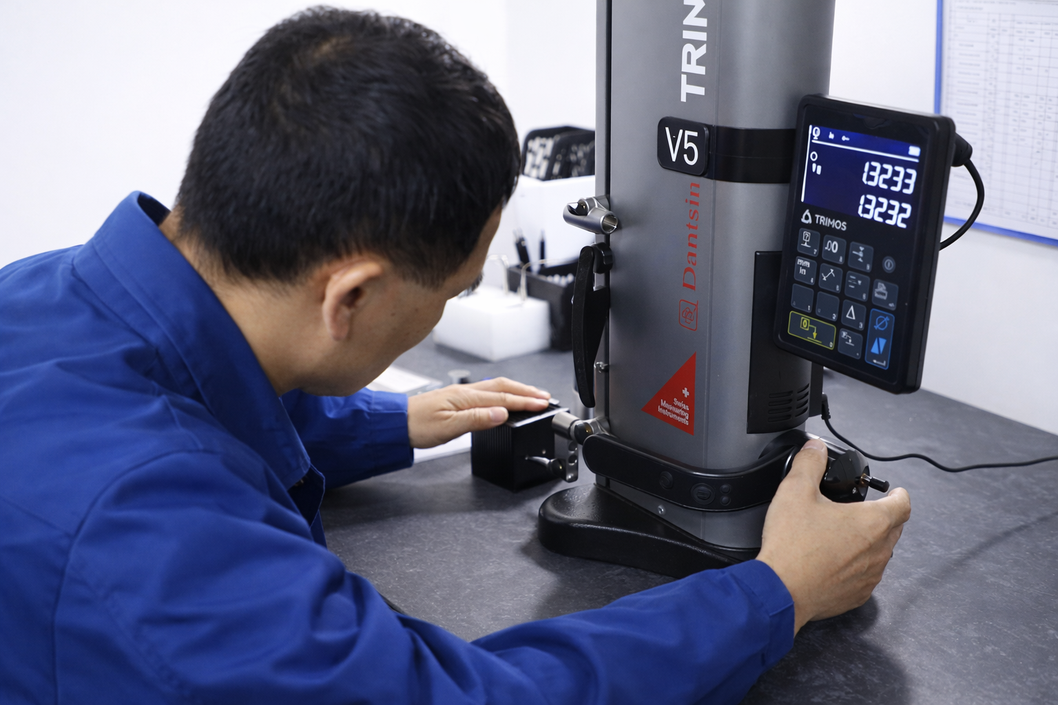
Dimensional inspection of die cast equipment housing parts before shipment.
Step 6 — Inspection and documentation. Quality control activities are regulated under a standardized ISO quality management system framework with three core inspection procedures: incoming material screening, continuous monitoring during production, and final testing before shipment. The quality lab uses a HEXAGON CMM, 2.5D optical comparators and TRIMOS high-precision height gauges, alongside micrometers, calipers and height gauges. Inspection follows IQC, IPQC, FQC and OQC stages, and documentation can include a FAI Report, Material Certificate, COC and Dimensional Inspection Report. All processing parameters and test data are recorded so that production and inspection records remain traceable per order.
Step 7 — Production ramp. Accepted parts move into repeat production. The minimum order quantity is 10 units, and the typical production lead time is 21–30 days.
Use Cases: Which Equipment Housing Suits Which Route
The route decision is easier when it is framed around the dominant requirement of the application rather than around process preference.
- Motor housings and gearbox covers. Dominant requirement: rigidity along a vibration path plus integrated cooling features. Integrated die casting, with secondary 3-axis CNC milling for bearing bores and fitting surfaces.
- Instrument housings. Dominant requirement: dimensional stability and repeatable sensor alignment, often with shielding. Zinc or magnesium die casting where wall thinness and EMI behaviour matter.
- Electronic enclosures and communication device housings. Dominant requirement: thin walls, integrated mounting bosses, and either shielding or thermal performance. Aluminum or zinc die casting with powder coating or plating.
- Heat sinks and thermal housings. Dominant requirement: fin geometry in one continuous piece — a natural fit for Heat Sink Die Casting Parts in aluminum.
- Household appliance housings and hardware fittings. Dominant requirement: high volume, stable appearance finish, low unit cost. Die casting, finished by powder coating or plating.
- Engineering prototypes and low-volume housings. Dominant requirement: contour complexity or volume too low for tooling. CNC machining from 3-axis to 5-axis, with prototypes in 3–5 days.
Comparison Table: Die Casting vs CNC Machining for Equipment Housings
| Decision factor | Die casting (integrated forming) | CNC machining |
|---|---|---|
| Forming principle | Molten alloy fills a die; the housing, ribs, bosses and flanges form in one step | Material removed from solid stock by rotating cutters under program control |
| Rigidity at joints | One continuous metal part — no splicing gaps | Stiffness depends on the stock and on how multi-piece designs are joined |
| Minimum wall thickness | 0.4 mm (zinc), 0.8 mm (aluminum) | Not limited by die fill; governed by tool access, cutter diameter and part deflection |
| Dimensional tolerance | ±0.01 mm | SUNPREC FANUC CNC machining centers hold a machine tolerance of 0.005 mm |
| Geometry it handles best | Thin-wall housings, reinforcing ribs, heat-sink fins, mounting bosses | Complex 3D contours, deep pockets, angled faces, tight-tolerance bores |
| Volume fit | High-volume repeat production | Prototypes in 3–5 days; low-volume manufacturing from 10 pcs |
| Secondary operations | Secondary 3-axis CNC milling for precise holes, grooves and fitting surfaces | Finishing applied after machining |
| Materials | Aluminum, zinc and magnesium alloys | Aluminum, stainless steel, carbon steel, brass, copper, titanium, POM, ABS, nylon, PEEK |
| Surface finishing | Anodizing, hard anodizing, powder coating, sandblasting, electroplating | Same one-stop finishing options |
| Typical equipment housing use | Equipment housing die casting parts, motor housings, electronic enclosures, heat sinks, instrument housings | Complex 3D contour machining, equipment housing components, prototypes and low-volume builds |
Long-Term Supply Continuity: What Buyers Should Contract For
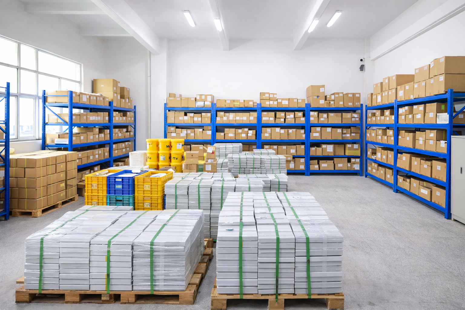
Finished goods storage supporting repeat die casting parts orders.
Process choice determines whether the first housing works. Supply terms determine whether the twentieth thousand does. For long-running equipment housing programs, four terms are worth fixing in writing:
- Capacity commitment. SUNPREC operates at a monthly production capacity of 4,200,000 units, which supports high-volume repeat production without re-qualifying a new source mid-program.
- Acceptance criteria. All finished precision components are accepted against customer-provided engineering drawings and specified dimensional tolerance limits through comprehensive metrology inspection. Physical sample comparison verification and formal inspection criteria agreed within a signed sales contract are both supported, and every inspection result is documented and archived.
- Commercial terms. Minimum order quantity is 10 units. SUNPREC supports Incoterms from EXW and FOB through to DAP and DDP. Common international payment methods including wire transfer and L/C are accepted. Typical production lead time is 21–30 days.
- Consistency mechanism. First-article inspection for every new batch, plus full traceability of processing parameters and inspection records, is the practical answer to batch-to-batch drift — the most common failure mode in a long-term die casting relationship.
SUNPREC HARDWARE CO., LTD is a Dongguan-based one-stop metal parts manufacturer established in 2020, working from a 3,500 m² facility with 200 employees, 10 engineers and an annual output of 5,000,000 units. Die casting, CNC machining and extrusion are produced in-house alongside surface finishing, with 90% of output exported to EU and USA markets and cooperation spanning more than 50 countries and over 300 clients.
FAQ
Does an equipment housing die casting supplier need IATF 16949:2016?
IATF 16949:2016 is the mandatory quality management system standard for die casting suppliers serving the automotive industry, so any housing program feeding automotive production requires it. For equipment housings outside automotive, the practical screening question is whether the supplier runs a documented quality system with traceable inspection records. SUNPREC regulates quality control activities under a standardized ISO quality management system framework, with incoming material screening, in-production monitoring and final testing before shipment, plus recorded processing parameters and test data for full traceability of production and inspection records.
What minimum wall thickness and tolerance can die casting achieve for an equipment housing?
SUNPREC die casting holds a minimum wall thickness of 0.4 mm for zinc and 0.8 mm for aluminum, with a dimensional tolerance of ±0.01 mm. Thin-wall capability is what allows a housing to carry integrated ribs, bosses and heat-sink fins in one piece. Where an interface needs tighter control than the as-cast surface, secondary 3-axis CNC milling is applied to precise holes, grooves and fitting surfaces.
What is the minimum order quantity for die cast equipment housing parts?
The minimum order quantity is 10 units, and the typical production lead time is 21–30 days. For very low volumes or housing geometries dominated by complex 3D contours, CNC machining is available instead, with 3-axis to 5-axis capability and prototypes delivered in 3–5 days.
How is a die cast equipment housing validated before mass production?
Validation starts with first-article inspection for every new batch. Dimensional testing is carried out with a HEXAGON CMM, 2.5D optical comparators and TRIMOS high-precision height gauges, together with micrometers, calipers and height gauges, following IQC, IPQC, FQC and OQC stages. Documentation packages can include a FAI Report, Material Certificate, COC and Dimensional Inspection Report, and acceptance is performed against customer-provided engineering drawings and specified dimensional tolerance limits.
How do buyers secure long-term supply continuity from Chinese die casting parts suppliers?
Supply continuity rests on four contract-level items: a stated capacity commitment, documented acceptance criteria, agreed commercial terms, and a repeatable first-article and traceability routine. SUNPREC operates at a monthly production capacity of 4,200,000 units, accepts orders from 10 units, works to a 21–30 day typical lead time, and supports Incoterms from EXW and FOB to DAP and DDP with common international payment methods including wire transfer and L/C. Next step: review your equipment housing drawing against these criteria — you can request a sample, a quotation, or the SUNPREC capability presentation from the SUNPREC official website.
Conclusion
Die casting and CNC machining are not competing answers to the same question — they answer different questions. If the equipment housing is a thin-walled, feature-rich structure that must be rigid without splices and produced at volume, die casting's one-step integrated forming is the right foundation, holding 0.4 mm walls in zinc, 0.8 mm walls in aluminum and ±0.01 mm tolerance. If the housing is defined by complex 3D contours, deep pockets or volumes below what tooling justifies, CNC machining from 3-axis to 5-axis is the practical route. And where a program needs both, the sequence is straightforward: die cast the body, then apply secondary 3-axis CNC milling to the precise holes, grooves and fitting surfaces.
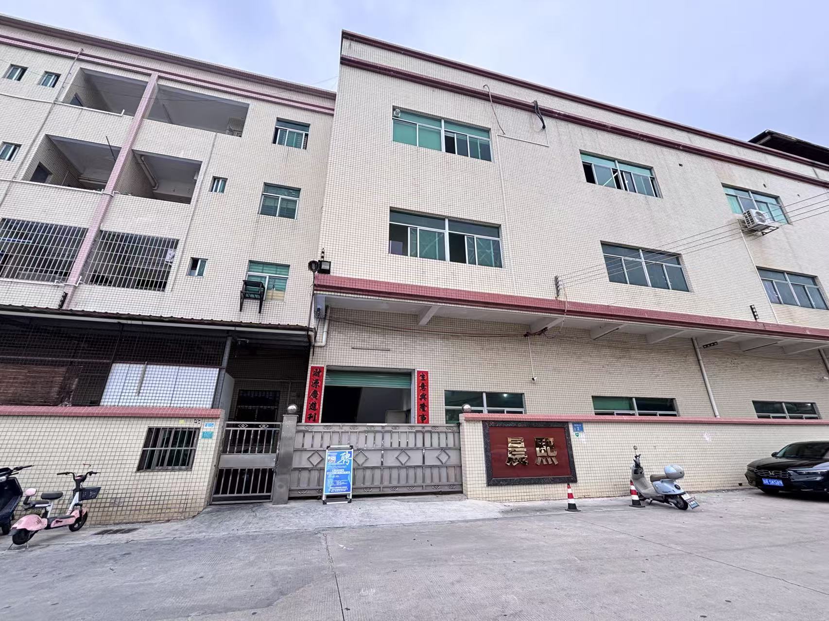
SUNPREC HARDWARE CO., LTD, Dongguan, China.
Send us your equipment housing drawing and we will tell you which route fits — die casting, CNC machining, or a combination of both.
SUNPREC CNC Machining · service@sunprec.com · TEL: +86-769-21686613 · No.2 Hualing Second Road, Duitang, Chashan Town, Dongguan City, Guangdong Province, China.
Download the full capability overview: SUNPREC Presentation – June 2026 (PDF)
Have Questions or Need More Details?
Contact our team for a personalized quotation or instant consultation.
Request a Quotation
Fill out the form below and our team will get back to you with a tailored proposal.
WhatsApp Direct Chat
Prefer to chat in real-time? Message us on WhatsApp for instant assistance & quick answers.
- Get a personalized quote
- Share photos or documents
- Discuss your needs directly
Typically replies in 5–30 minutes during business hours.