Understanding Die Spring Load Deflection Curves: A Technical Guide for Tool Designers
A die spring load deflection curve is a graph that plots the force a spring produces against the distance it is compressed. For a tool designer, that curve - not the catalog part number - decides whether a spring holds its working load through millions of press strokes or loses it a few weeks into production.
This technical guide explains how to read die spring load deflection curves in day-to-day tooling work: how to convert a tooling requirement into a working load and stroke, how load class color coding narrows the choice across ISO 10243, JIS B5012 and American Standard (Inch series) catalogs, and how construction details - rectangular wire geometry, ground end faces, multi-stage tempering and shot peening in 55CrSi chrome silicon steel - change both the shape of the curve and its stability over the life of the tool.
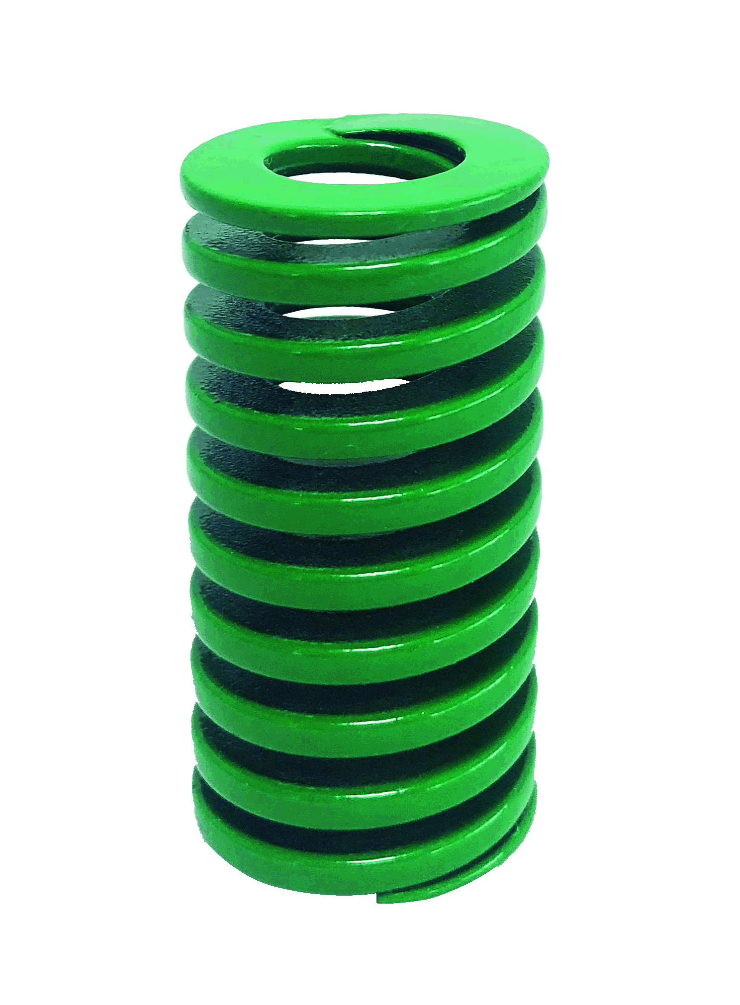
Why Die Spring Selection Fails When the Curve Is Ignored
Specification problems in die springs are usually curve-reading problems rather than material problems. Four of them account for most of the rework seen on the shop floor.
- Selecting by outside diameter and free length only. The pocket tells you what will fit. The curve tells you what the spring will actually deliver at the working stroke. Two springs that fit the same hole can behave completely differently.
- Ignoring the deflection percentage. Every load class has a practical deflection envelope. Beyond that envelope, the spring loses free length and load accuracy.
- Installing with no preload. Recommended practice is an initial preload - typically 5% to 10% of free length - to eliminate internal play and to prevent the severe shock loads created by sudden impact during the press stroke. Springs run without preload can chatter, buckle laterally and fail structurally well before their fatigue limit.
- Mixing up color standards. Color coding identifies load class on the shop floor, but the colors are not universal. The same color can mean different things in different catalog systems.
The practical consequence is that a die can be assembled with a spring that is dimensionally correct, visually correct, and still wrong. Load deflection data is the only document that closes that gap.
How Standards Shape the Curves You Can Buy
Three catalog systems dominate international tooling, and each organizes load and dimension data a little differently.
ISO 10243 standardizes color-coding and dimensions for rectangular-section compression springs used in press tools. The ISO system is organized around the housing and rod geometry of the tool, so a spring selected against the ISO tables is defined largely by the pocket it sits in.
JIS B5012 specifies allowable tolerances of the inner and outer diameters of springs. The Japanese system therefore emphasizes the tolerance of the spring itself rather than the mounting hole, which becomes a meaningful difference when one tool is maintained with parts drawn from more than one catalog family.
American Standard (Inch series) uses inch-based dimensions and its own load class structure, which is why inch-series springs are specified separately from metric catalogs even when the pocket dimensions are close.
Materials sit underneath all three systems. Rectangular wire die springs - including chrome silicon die springs - are made from high-stress oil-tempered alloy steels such as 55CrSi, selected for tensile strength, purity and resistance to permanent set. The rectangular cross-section is the reason these springs are used in tooling at all: it stores up to 30% to 50% more energy than a round wire spring of the same footprint, which lets a designer reach a required force in a smaller pocket or at a shorter stroke.
Demand tracks industrial output rather than fashion. The global industrial springs market is projected to reach USD 7.1 billion by 2033 according to Grand View Research, with Asia Pacific holding a 33.4% revenue share in 2024. Automotive stamping - one of the largest application groups for die springs - was valued at USD 87.98 billion in 2024 by Market Research Future.
Reading a Die Spring Load Deflection Curve: The Six Variables That Matter
1. Load at a defined deflection
Curves are published as load values at specific deflection points rather than as one headline number, because the relationship is what matters. Across the working range that relationship is effectively linear: load rises in proportion to deflection, and the ratio between the two is the spring rate - the slope of the curve. A steeper slope means more force for the same travel, which is exactly what a heavier load class provides.
2. Load class and color coding
Load classes let a designer change the slope of the curve without changing the outside diameter, the inner diameter or the free length. They are identified in service by powder coated color.
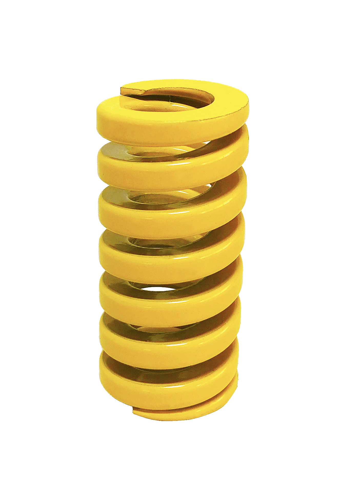
- ISO 10243 series: CIF super minimal load (light green), CIL light duty load (green), CIM medium duty load (blue), CIH heavy duty load (red), CIB extra heavy duty load (yellow).
- JIS B5012 series: CSWF minimal load (yellow), CSWL light load (blue), CSWM medium load (red), CSWH heavy load (green), CSWB extra heavy load (brown), CSWG super heavy load (black).
- American Standard (Inch series): medium duty (blue), medium heavy duty (red), heavy duty (gold), extra heavy duty (green).
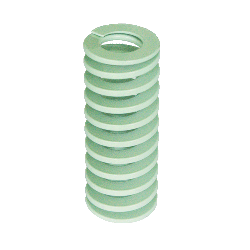
Note where the systems diverge. Green indicates a light duty load in the ISO CI series but a heavy load in the JIS CSW series. Brown appears only in the JIS system, and the American series uses green for its heaviest class. Color is an identification aid inside a standard, not a cross-standard language, so a color-coded spring should always be replaced against the same standard family it was selected from.
3. The deflection envelope
The most useful number on a die spring curve is not the load - it is the deflection the spring can accept while still delivering the fatigue life the tool needs. Across these rectangular wire series, working deflection spans roughly 12% to 40% of free length, and the 3 to 5 million cycle fatigue life is achieved by operating within the recommended limits rather than at the top of the range. Long-life selection commonly targets about 30% to 35% of free length.
Deflection percentage is calculated as working stroke divided by free length. If a required stroke pushes the percentage above the envelope, the correct response is to increase free length or move to a lighter class - not to accept over-deflection and expect the spring to survive it.
| Design reference parameter | Value |
|---|---|
| Working deflection range | 12% - 40% of free length |
| Long-life deflection target | approximately 30% - 35% of free length |
| Recommended preload | 5% - 10% of free length |
| Fatigue life within recommended deflection | 3,000,000 - 5,000,000 high-frequency compression cycles |
| Energy storage versus round wire, same footprint | up to 30% - 50% higher |
| Material | 55CrSi (Chrome Silicon), oil-tempered |
4. Preload and the real starting point of the curve
A spring installed with no preload does not start its stroke at zero load - it starts it at zero contact. A preload of 5% to 10% of free length removes that play, keeps the spring seated against both end faces, and eliminates the shock loading that appears when the press takes up slack. On the curve, preload simply shifts the working window up the slope; the shape of the curve does not change, but the load the die actually sees does.
5. Ground ends
Closed and ground ends are machined so that the end faces are parallel. That parallelism produces squareness and perpendicular load distribution, which eliminates lateral deflection and protects the mold guide components. In curve terms, ground ends guarantee that the installed height - and therefore the starting point of the working stroke - is the same on every spring in the tool. With un-ground ends, that starting point varies from spring to spring and the force balance of the die varies with it.
6. Material, tempering and shot peening
A load deflection curve is measured on a new spring. What a tool designer actually needs is the curve after two million strokes at temperature, and that is where processing shows up.
- Multi-stage tempering minimizes thermal relaxation and load loss during continuous high-temperature stamping, and maintains nominal free length and load accuracy under elevated ambient temperatures and long-term preload.
- Controlled shot peening introduces compressive stress into the wire surface, raising the fatigue limit and preventing micro-crack propagation.
- Trapezoidal wire profile geometry minimizes internal stress concentration during high-frequency, millions-cycle compression operation.
- Full material traceability - mill test certificates and heat-number records on the raw wire - is what allows a replacement spring to be matched to the specification of the original rather than to its appearance.
Together these processes are what allow a 55CrSi die spring to hold its published load across a fatigue life in the range of 3 to 5 million compression cycles instead of drifting downward as the tool runs.

Step-by-Step: Selecting a Die Spring from Its Curve
- Define the required force. Establish the load the tool needs at the working position - the force required where the die performs its work, not at the end of travel.
- Define the working stroke. Measure the total travel between the installed height and the fully compressed height.
- Measure the pocket. Hole diameter, guide pin or rod diameter and available spring length set the maximum outer diameter, inner diameter and free length. The ISO 10243 series covers outer diameters from 10 mm to 63 mm, inner diameters from 5 mm to 38 mm and free lengths from 25 mm to 305 mm; the JIS B5012 series covers outer diameters from 6 mm to 70 mm, inner diameters from 3 mm to 38.5 mm and free lengths from 10 mm to 350 mm; the American Standard series covers outer diameters from 10 mm to 51 mm, inner diameters from 4.76 mm to 25.4 mm and free lengths from 25 mm to 305 mm.
- Convert stroke into a deflection percentage. Divide the working stroke by the free length of the candidate spring and multiply by 100.
- Check the percentage against the envelope. Compare the result with the 12% to 40% working range and select a longer free length if the result sits at the top of it.
- Set the life target. For a tool expected to run into millions of cycles, keep deflection closer to the 30% to 35% long-life range.
- Choose the load class that meets the force requirement at that deflection. Select from within the correct standard family, and confirm the color against the same standard rather than against a different one.
- Add preload and re-check. Include 5% to 10% of free length of preload in the installed height, then confirm that total deflection, preload included, still fits the envelope.
- Confirm the environment and validate. Temperature, cycle rate and exposure to oil or coolant all influence the effective curve. Validate the final choice with a physical sample before committing a production tool.
Use Cases: Where Deflection Control Decides Tool Life
Rectangular wire die springs are used in automotive stamping dies, plastic injection molds, die-casting tooling, industrial automation, elevator systems, machine tools, engineering machinery, environmental filtration equipment, high-voltage electrical switches, valves and heavy-duty energy systems. The working conditions these applications share - high-frequency cyclic shock, continuous high-temperature operation, high-load compression, oil and coolant exposure and extreme dynamic stress - are the reason deflection percentage, rather than nominal load, is the usual limiting factor.
Where cycle rates are high and the die runs continuously, the deflection percentage and the fatigue limit of the wire surface dominate the decision; this is the case where shot peening and the trapezoidal wire profile matter most. Where dies run hot, thermal relaxation resistance decides whether the curve selected in the office is still the curve in the press after a shift, which is where multi-stage tempering earns its place. Where springs sit in pockets exposed to stamping lubricants and coolants, the powder coating has to resist both moisture and abrasion so that it neither corrodes nor contaminates a precision cavity.
Two patterns show up repeatedly across these applications. The first is the force-balanced die: when several springs share a load, a deflection percentage that is safe in isolation can become uneven in practice if free lengths or preloads differ, so matched free length and ground ends matter more than moving to a single heavier load class. The second is the long-travel die: where stroke is the constraint, a lighter class run at a controlled percentage frequently outlasts a heavier class run at an aggressive one, because fatigue life responds to deflection, not to the load label.
Comparison Table: Load Classes, Colors and Dimensions by Standard
The table below summarizes the load class, color and dimensional data that appear on the load deflection curves of the three main catalog systems. It is a reference for reading a curve, not a cross-standard equivalence chart: colors and class names are defined inside each standard.
| Standard | Load classes and color codes | Dimensional range | Material and end condition |
|---|---|---|---|
| ISO 10243 Standard Spring | CIF super minimal load (light green); CIL light duty load (green); CIM medium duty load (blue); CIH heavy duty load (red); CIB extra heavy duty load (yellow) | OD 10 - 63 mm; ID 5 - 38 mm; free length 25 - 305 mm | 55CrSi (Chrome Silicon); closed and ground or closed un-ground ends; powder coated |
| JIS B5012 Standard Die Spring | CSWF minimal load (yellow); CSWL light load (blue); CSWM medium load (red); CSWH heavy load (green); CSWB extra heavy load (brown); CSWG super heavy load (black) | OD 6 - 70 mm; ID 3 - 38.5 mm; free length 10 - 350 mm | 55CrSi (Chrome Silicon); closed and ground or closed un-ground ends; powder coated |
| American Standard Spring | Medium duty (blue); medium heavy duty (red); heavy duty (gold); extra heavy duty (green) | OD 10 - 51 mm; ID 4.76 - 25.4 mm; free length 25 - 305 mm | 55CrSi (Chrome Silicon); closed and ground or closed un-ground ends; powder coated |
Read together with a published curve, this table answers the first question a tool designer asks: which family does the tool belong to, and which class within that family changes the slope of the curve without changing the pocket.
Frequently Asked Questions
Which standards define die spring load classes and color codes?
ISO 10243:2019 standardizes color-coding and dimensions for rectangular-section compression springs used in press tools. JIS B5012 specifies allowable tolerances of the inner and outer diameters of springs, and the American Standard (Inch series) defines its own inch-based classes. The color systems differ: the ISO series runs light green, green, blue, red and yellow from super minimal to extra heavy duty load; the JIS series runs yellow, blue, red, green, brown and black from minimal to super heavy load; the American series uses blue, red, gold and green for medium duty through extra heavy duty. Because green means light duty in one system and heavy load in another, a spring should always be re-ordered against the standard family it was designed into.
How far can a rectangular wire die spring be compressed before fatigue life is affected?
Working deflection across these series spans roughly 12% to 40% of free length. Within the recommended deflection limits, the springs are designed for a fatigue life of 3 to 5 million high-frequency compression cycles, and long-life selection typically targets about 30% to 35% of free length. Deflection percentage is working stroke divided by free length, so the practical control is to lengthen the spring rather than to push a shorter one past its envelope. Installing with an initial preload of 5% to 10% of free length belongs to the same discipline, because it removes internal play and the shock loading that appears when the press takes up slack.
What happens if the original curve data is missing and only a physical sample is available?
Custom and OEM/ODM manufacturing covers non-standard outer and inner diameters, non-standard free lengths, specialized trapezoidal wire cross-sections, custom load rates, specialized surface treatments and private-label color or laser marking, based on customer drawings or physical samples. Raw material is supplied with Mill Test Certificates and full heat-number traceability, so a replacement spring can be validated against the material and load class of the original rather than against a visual match alone.
What lead time should a tool designer plan for?
Standard ISO 10243, JIS B5012 and American catalog items are held in stock, which allows dispatch within 24 to 48 hours for stock orders. Custom engineered or bulk OEM orders are typically delivered within 2 to 3 weeks, supported by automated coiling and grinding lines and flexible production scheduling. Large inventory lots are managed under FIFO and batch-tracking controls so that spare springs remain interchangeable with the originals over the life of the tool.
Can die springs from a Chinese manufacturer be used as drop-in replacements in existing tools?
Drop-in replacement depends on dimensional compatibility and load class rather than on the country of origin. TOPWAY SPRINGS - the spring brand of Dalian TopWay Precise Mould & Die Co., Ltd., founded in 2012 - manufactures rectangular wire die springs to ISO 10243, JIS B5012 and American Standard (Inch series) specifications, the same systems used by international mold component catalogs, in a 16,500 square metre facility in Dalian, Liaoning, China. Samples and curve data can be requested for validation before a tool is committed: contact Liya at liya@chs-spring.com or WhatsApp +86 151-4047-4905. The full product range is listed in the downloadable catalog linked at the end of this guide.
Conclusion
Die spring load deflection curves turn a tooling requirement into a specification. Read in the right order, they answer four questions: what force the spring produces at the working stroke, how much deflection it can accept, which load class provides the required slope, and how stable that curve remains at temperature and across millions of cycles.
The recurring mistakes are predictable: choosing by pocket size alone, running a spring beyond its deflection envelope, skipping preload, and treating color as a universal language when ISO 10243, JIS B5012 and American Standard each define their own classes. Rectangular wire geometry, closed and ground ends, multi-stage tempering and controlled shot peening in 55CrSi chrome silicon steel exist to keep the published curve valid in service, not only on the test bench.

Need curve data, a sample, or a quote?
TOPWAY SPRINGS manufactures ISO 10243, JIS B5012 and American Standard rectangular wire die springs at its 16,500 square metre facility in Dalian, China, with an annual output of 3,600,000 pieces and a 50% export share across EU and USA markets. Standard catalog items ship from stock; custom springs are engineered from drawings or physical samples.
Download the catalog: Dalian TopWay product catalog (PDF)
Website: www.onetopway.com
Email: liya@chs-spring.com
WhatsApp: +86 151-4047-4905
Have Questions or Need More Details?
Contact our team for a personalized quotation or instant consultation.
Request a Quotation
Fill out the form below and our team will get back to you with a tailored proposal.
WhatsApp Direct Chat
Prefer to chat in real-time? Message us on WhatsApp for instant assistance & quick answers.
- Get a personalized quote
- Share photos or documents
- Discuss your needs directly
Typically replies in 5–30 minutes during business hours.