
GM37-555PM vs TWG3246-TEC2430: Brushed Spur or Brushless Worm for Low-Speed Positioning?
Two gear motors from the same 12 V–24 V family, with the same 8.0 kg.cm maximum rated torque and the same 0.5/0.6 module, can still behave like different components on a positioning axis. The GM37-555PM is a brushed DC spur gear motor with a 5–800 rpm output band. The TWG3246-TEC2430 is a brushless DC worm gear motor with a 3–35 rpm output band. What actually separates them in a machine design is not torque but commutation, minimum usable speed, spark and EMI tolerance, duty cycle, and the space available for a 46 mm worm gearbox.
Direct answer for buyers and design engineers:
- Choose the GM37-555PM when the axis needs an output speed anywhere between 5 rpm and 800 rpm, when the drive electronics must stay simple, when duty is intermittent or cost-sensitive, and when brush sparking and carbon dust are acceptable in the enclosure.
- Choose the TWG3246-TEC2430 when positioning happens between 3 rpm and 35 rpm, when the drive runs continuously or the maintenance interval must be long, when spark-free operation matters (miniature medical devices, precision instruments), and when a 46 mm gearbox length fits the housing.
- Do not choose on torque. Both models are rated at 8.0 kg.cm maximum, so the decision must be made on speed band, duty, spark constraints, control architecture and envelope.
What "low-speed positioning" actually asks of a gear motor
Low-speed positioning is a duty in which the output shaft moves a mechanism between defined positions at a low output speed, stops, holds, and repeats. The gearbox dominates the torque multiplication and the mechanical resolution in that duty; the motor dominates wear, sparking, heat, control complexity and service life. That split is why two motors with identical rated torque can be the right and the wrong answer for the same axis.
Before comparing catalogue rows, define four constraints:
- Minimum and maximum output speed. A 3–35 rpm motor cannot replace a 5–800 rpm motor on a mechanism that needs 120 rpm for its rapid-traverse move, and a 5–800 rpm brushed motor asked to hold 4 rpm sits outside its documented band.
- Duty cycle and life target. Continuous, high-frequency start-stop and long-life duties push the decision towards brushless commutation, while short-running, cost-sensitive duties can stay brushed.
- Spark, carbon dust and EMI tolerance. Brushed motors produce electrical sparks and carbon dust during operation, which creates strong electromagnetic interference. Brushless motors have no physical brush contact and no sparks, and exhibit low electromagnetic interference. In a fluid-handling instrument or a sealed sensor housing, that difference is a design constraint rather than a preference.
- Envelope and control architecture. The worm unit has a single 46 mm gearbox length; the spur unit is built in 19, 21.5, 24, 26.5 and 29 mm gearbox lengths across its stage counts. The brushless unit also needs a driver, while the brushed unit runs from simple DC switching.
The most common specification error in this comparison is treating the shared 8.0 kg.cm rating as proof of interchangeability. It is not. It only proves that both motors can deliver the same maximum rated torque under their specified operating conditions.
Industry background: why both architectures still ship in 2026
Miniature DC gear motors sit inside a market that keeps adding brushless variants without retiring brushed ones. Grand View Research sizes the global brushless DC motor market at approximately USD 22.2–22.33 billion for 2025, and OEC records USD 16.3 billion in 2024 global export value for electric motors with an output below 37.5 W under HS code 850110. Those figures describe category scale, not a verdict on any single axis design: both a brushed spur gear motor and a brushless worm gear motor belong to that trade flow.
The direction of travel is visible in adjacent standards work. IEC 60034-30-1:2025 introduced the IE5 ultra-premium efficiency class, and EU Regulation (EU) 2019/1781 sets minimum efficiency performance levels for mains-fed motors in the 0.12 kW–1000 kW band, with IE3 required from 0.75 kW and IE2 below it. Buyers of 12–24 V miniature gear motors should treat those frameworks as context rather than a shortcut: the practical specification work for a 12 V or 24 V positioning axis still runs on rated torque, speed band, duty and thermal behaviour, and it is worth asking a supplier directly whether any efficiency declaration applies to your configuration.
In application terms, the two markets have separated along maintenance tolerance. Smart home equipment, automated equipment and automated production lines remain served by brushed spur gear motors because drive electronics stay simple and initial cost is lower. Miniature medical devices, precision automated instruments and electrically adjustable supports move towards brushless worm gear motors because service access is limited and no-spark operation is a functional requirement.
Both models in this comparison are built by TT Motor (Shenzhen) Industrial Co., Limited, a miniature DC motor manufacturer established in Hong Kong, China in 2006 and headquartered in Bao'an District, Shenzhen. The company operates roughly 9,000 square metres of manufacturing area with more than 300 employees, 35 engineers and an annual output of 8,000,000 pieces, exporting about 70% of production to the EU and USA. Its quality management system is certified to ISO 9001:2015 under certificate F02926Q00865R402 issued by DCI, valid from 21 August 2026 to 21 August 2029, covering R&D and manufacture of micromotors (DC gear motor, DC brushless motor), 3C excluded.
The two candidates, spec by spec
Both models share a 12 V–24 V DC supply, an 8.0 kg.cm maximum rated torque, a 0.5/0.6 module and the same material set of stainless steel, iron and copper. Beyond that, the specifications diverge in ways that map directly onto positioning duties.
GM37-555PM — brushed DC spur gear motor
The GM37-555PM is a DC brush spur gear motor with a 5–800 rpm output band and 2, 3, 4, 5 or 6 gear stages. Gearbox length is 19 mm, 21.5 mm, 24 mm, 26.5 mm or 29 mm depending on the stage count. The wide speed band makes it usable as a single platform across a machine family: a fast traverse at the top of the band and a slower approach move lower down, with the stage count chosen to match the required reduction.
Its documented application fields are smart home, automated equipment and automated production lines. Mechanically it is the shorter of the two options, which matters when the axis sits inside a compact appliance chassis or on a conveyor module where axial length is already tight.
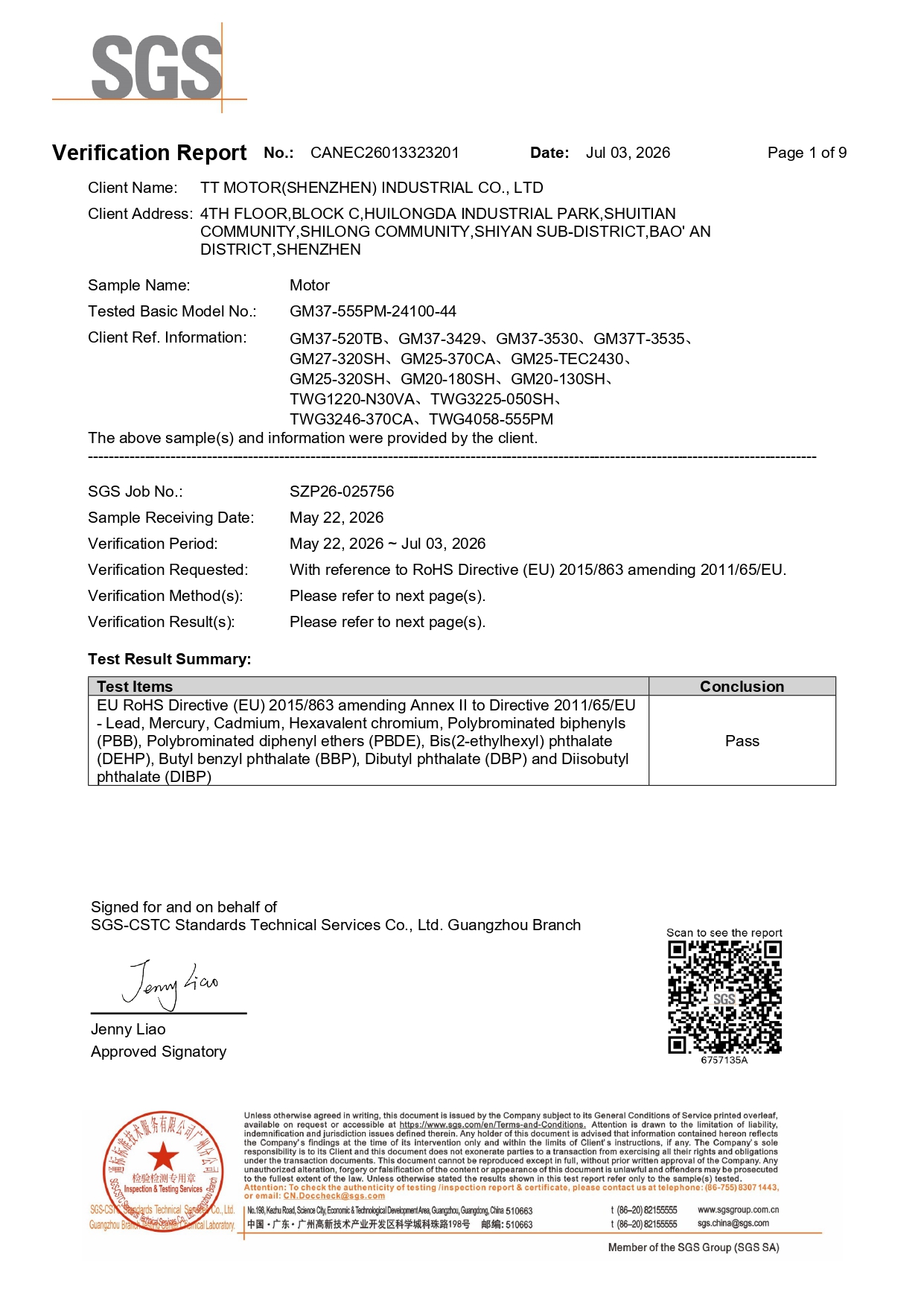
Compliance documentation for the model is model-specific: SGS report CANEC26013323201, issued 3 July 2026, covers DC gear motors including the GM37-555PM with reference to the RoHS Directive (EU) 2015/863.
TWG3246-TEC2430 — brushless DC worm gear motor
The TWG3246-TEC2430 is a DC brushless worm gear motor with a 3–35 rpm output band and 3, 4 or 5 gear stages, all built on a 46 mm gearbox length. The narrow low-speed band is the point of the design: the gearbox is configured to deliver its useful output in the single-digit to mid-thirty rpm range, where many positioning and dispensing mechanisms operate.
Its documented application fields are miniature medical devices, precision automated instruments and electrically adjustable supports. Commutation is electronic, so there is no brush or commutator wear path in the drive, and no sparking at the commutation interface.
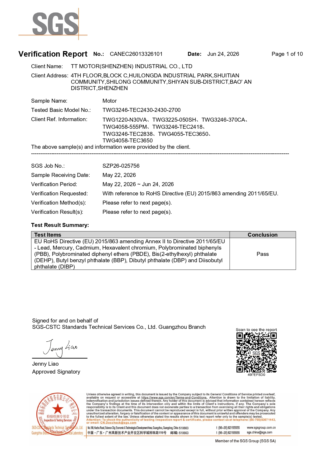
Its RoHS documentation is separate from the spur model: SGS report CANEC26013326101, issued 24 June 2026, covers DC gear motors including the TWG3246-TEC2430 with reference to the RoHS Directive (EU) 2015/863.
What the architecture difference means on a real axis
Service life and maintenance. Brushed motors experience frictional losses at the brush interface and are commonly referenced at a service life in the range of several hundred to several thousand hours. Brushless motors generate less heat, are commonly referenced at a service life of tens of thousands of hours, and offer higher power density. For an instrument that runs daily in a clinic, that gap converts into a maintenance schedule rather than a datasheet line.
Electrical noise. A brushed motor produces sparks and carbon dust while running, which is a strong source of electromagnetic interference. A brushless motor has no physical contact at the commutation point and produces no sparks, so interference is low. Where the motor shares an enclosure with sensitive measurement electronics, or where the mechanism handles samples and fluids, this is often the deciding factor rather than torque or speed.
Control complexity and cost. Brushed motors are simple to control and fit cost-sensitive designs with modest life requirements and simple logic. Brushless motors are more complex to control and need a driver, but they run with virtually no maintenance and can produce a lower total cost over a long service window. The trade is upfront electronics and engineering time against field service and replacement cost.
Gearbox form. The spur gearbox is built in five length options from 19 mm to 29 mm and is the compact choice when the axis is short. The worm gearbox is fixed at 46 mm but concentrates the reduction into a low-speed output band of 3–35 rpm. If the mechanism must hold position with the power removed, ask the supplier to confirm the holding behaviour of the worm stage for your specific load and lead angle rather than assuming it.
Step-by-step selection sequence
The following six steps resolve most GM37-555PM versus TWG3246-TEC2430 decisions without a prototype round.
Step 1 — Lock the required output speed range
Calculate the output rpm needed for the fastest move and the slowest positioning move. If either end falls outside 3–35 rpm, the brushless worm model is excluded on speed alone. If the mechanism never needs more than 35 rpm, both remain candidates and the decision moves to duty and environment.
Step 2 — Set the duty cycle and life target
Define how many hours per year the axis runs, how often it starts and stops, and what service interval the equipment can tolerate. Long continuous operation, high start-stop frequency and high life requirements point to brushless commutation. Short running time and low cost sensitivity to initial price point to brushed.
Step 3 — Screen spark, dust and EMI constraints
Check the enclosure, the certification plan and the surrounding electronics. Any requirement for spark-free operation, low electromagnetic interference, or freedom from carbon dust excludes the brushed option on principle, regardless of its speed advantage.
Step 4 — Check the mechanical envelope
Measure the axial space behind the mounting face. The spur unit offers 19 mm to 29 mm gearbox lengths; the worm unit requires 46 mm. A 46 mm gearbox that does not fit will force a redesign that costs more than the motor.
Step 5 — Match the control architecture and feedback
Confirm what the existing board can drive. A brushed motor runs from straightforward DC switching; a brushless motor needs a driver matched to its commutation. If the axis needs position feedback, both models can be specified with an encoder as a customization option, alongside shaft, gearbox, voltage, logo and speed customization.
Step 6 — Close documentation and acceptance before tooling
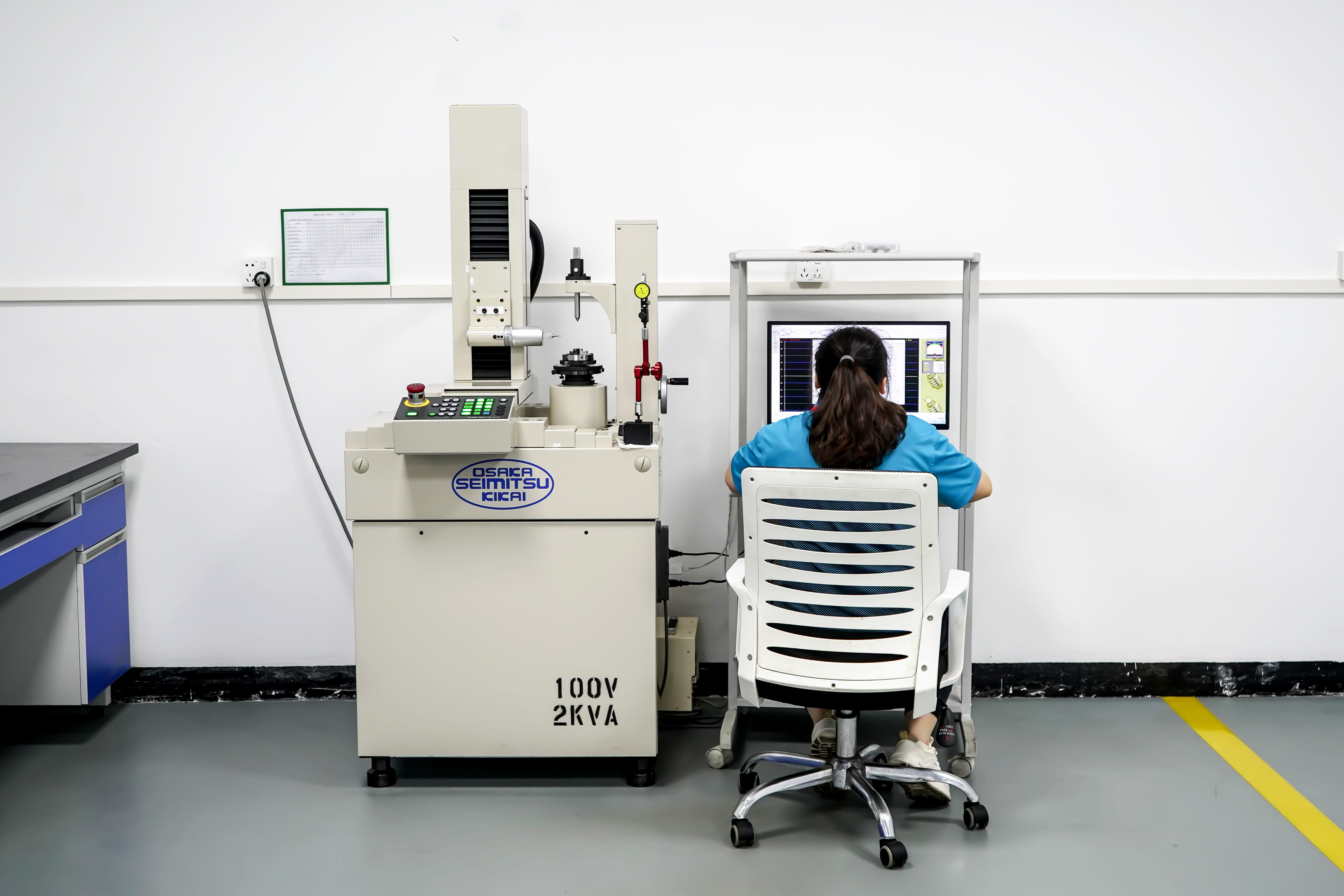
Request the RoHS report for the exact model, agree the acceptance test, and lock the parameters that will be inspected. The acceptance criteria used for these orders are pre-shipment testing, and production follows a 100% test procedure in which all units undergo 100% testing as part of production inspection.
Use cases: which axis takes which motor
Automated production lines and general automated equipment. The GM37-555PM is the natural fit where a station needs a fast indexing move plus a slower approach, and where the control cabinet already provides simple DC switching. Its documented application field includes automated equipment and automated production lines, and its five gearbox lengths let several machine variants share one motor platform.
Smart home mechanisms. Cost, compactness and simple drive electronics dominate here, and the brushed spur model is documented for smart home use. The 19–29 mm gearbox length is often the reason it wins over a longer worm unit inside an appliance housing.
Miniature medical devices and pump drives. The TWG3246-TEC2430 is documented for miniature medical devices, and a UK medical device manufacturer has used it, alongside other TT Motor models, to drive a medical pump in volumes of 500–2,000 units per year over a relationship of three years or more. The reported result was stable output under long-term operating conditions with reduced equipment maintenance frequency, based on low noise, low vibration and long lifespan.
Precision automated instruments and electrically adjustable supports. These are the two remaining documented fields for the brushless worm model. Both share a profile of low-speed movement, limited service access and a preference for no-spark operation.
Conveying and sorting. A US logistics equipment company used the GM37-555PM, together with the GMP36-TEC3650 brushless planetary model, to drive conveyor and sorting mechanisms across a fleet of about 1,000 units over three years or more, reporting stable operation under frequent start-stop and load changes. The lesson is not that one architecture covers every conveyor axis, but that the brushed spur model remains viable where start-stop frequency is high and the enclosure tolerates brush behaviour.
Comparison table: documented specifications only
The table below uses only the published specification and certification data for the two models. It is intended as a screening tool, not a substitute for a load calculation.
| Parameter | GM37-555PM | TWG3246-TEC2430 |
|---|---|---|
| Motor type | DC brush spur gear motor | DC brushless worm gear motor |
| Commutation | Mechanical, via brushes and commutator | Electronic |
| Rated voltage | DC 12 V–24 V | DC 12 V–24 V |
| Rated torque (max) | 8.0 kg.cm | 8.0 kg.cm |
| Speed range | 5–800 rpm | 3–35 rpm |
| Number of gear stages | 2 / 3 / 4 / 5 / 6 | 3 / 4 / 5 |
| Gearbox length | 19 / 21.5 / 24 / 26.5 / 29 mm | 46 mm |
| Module | 0.5 / 0.6 | 0.5 / 0.6 |
| Materials | Stainless steel, iron, copper | Stainless steel, iron, copper |
| Spark and carbon dust | Produced during operation | None, no brush contact |
| Electromagnetic interference | Strong, from sparking | Low |
| Reference service life | Several hundred to several thousand hours | Tens of thousands of hours |
| Control requirement | Simple DC switching | Requires a brushless driver |
| Documented industries | Smart home, automated equipment, automated production line | Miniature medical devices, precision automated instruments, electrically adjustable supports |
| RoHS report (SGS) | CANEC26013323201, issued 3 July 2026 | CANEC26013326101, issued 24 June 2026 |
Where each option stops fitting
The GM37-555PM is the wrong choice when the axis must run continuously for a long service window without maintenance access, when the enclosure cannot tolerate carbon dust or sparking, when the surrounding electronics are sensitive to electromagnetic interference, or when the required positioning speed sits below 5 rpm.
The TWG3246-TEC2430 is the wrong choice when any move requires more than 35 rpm, when the available board cannot host a brushless driver, when the housing cannot accommodate a 46 mm gearbox length, or when the lowest possible initial cost is the dominant project constraint.
A third consideration is documentation scope. Do not assume a compliance file transfers between models. In this supplier's documentation set, the CE certificate CTL2512182011-EC issued by CTL covers the GM12-N20VA and related models, not the two motors compared here, so any CE/EMC requirement for the GM37-555PM or the TWG3246-TEC2430 must be requested and confirmed for the exact model and configuration.
Frequently asked questions
Do the GM37-555PM and TWG3246-TEC2430 both have RoHS documentation?
Yes. Each model has its own SGS report referencing the RoHS Directive (EU) 2015/863. The GM37-555PM is covered by report CANEC26013323201 issued 3 July 2026 for DC gear motors including that model. The TWG3246-TEC2430 is covered by report CANEC26013326101 issued 24 June 2026 for DC gear motors including that model. Because the scopes are model-specific, request the report matching the exact motor you are ordering.
Can these motors be customized for an OEM design?
Yes. OEM and ODM production services are both available, and customization covers shaft, encoder, gearbox, voltage, logo and speed. That means a positioning axis can be specified with an encoder for feedback, with a shaft geometry that matches an existing coupling, and with the gearbox stage count that produces the required output speed. Production applies a 100% test procedure, so all units undergo 100% testing as part of production inspection.
What is the minimum order quantity and the purchasing terms?
The minimum order quantity is 2 pieces. Delivery terms are EXW, acceptance criteria are pre-shipment test, and payment terms are 100%. For a first evaluation this structure keeps the entry cost low, since a two-piece order allows the motor to be tested on the actual mechanism before any volume commitment.
How can a buyer avoid qualified samples but inconsistent batch performance?
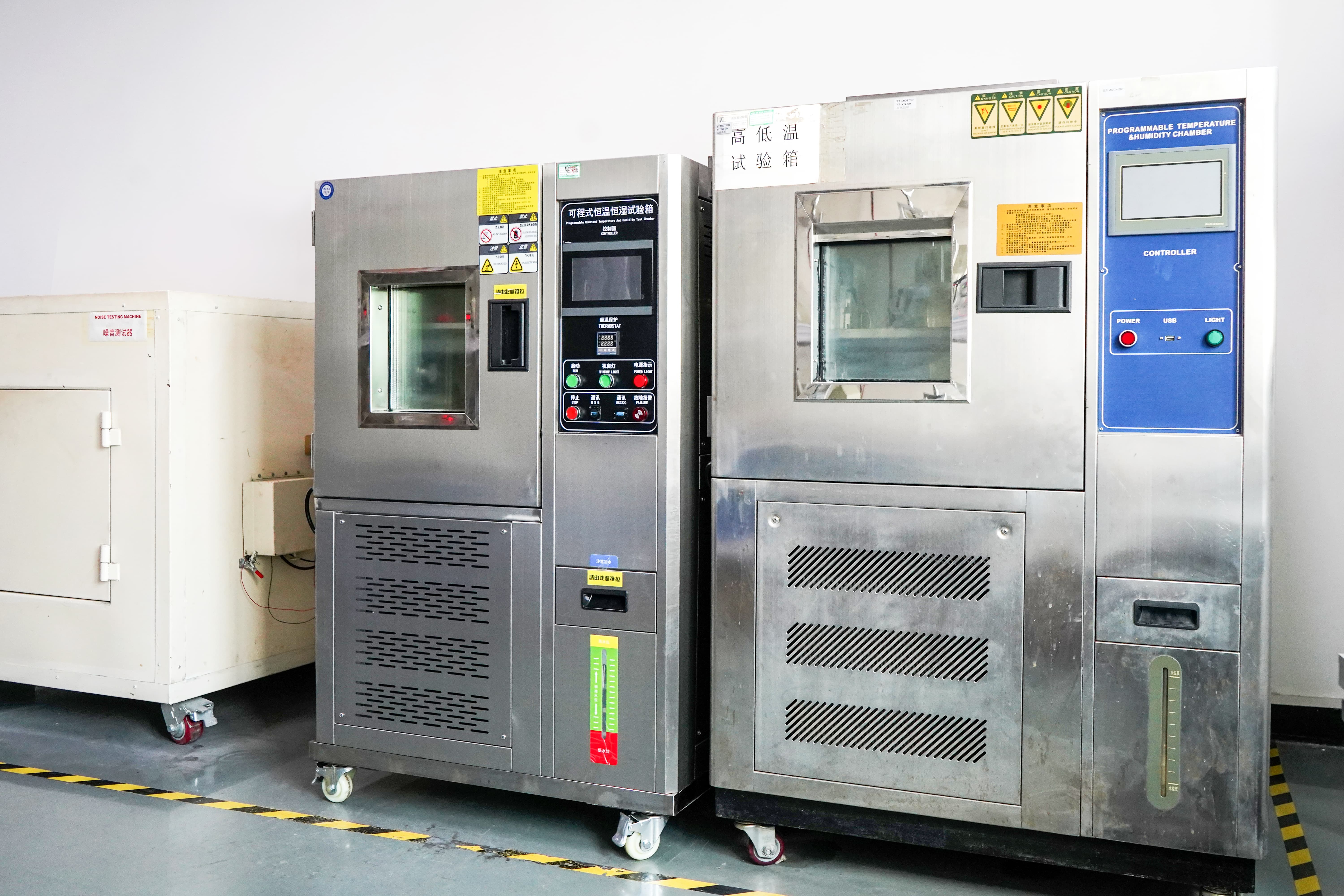
The mitigation is procedural. Define the motor parameters and acceptance standards before mass production, run a small-batch trial production, establish a shipment inspection mechanism, and only then release mass production. Avoid special machine adjustment for samples, avoid using one raw material for samples and another for volume, and require notification in advance plus re-verification if raw materials, components or production processes change. A traceability system helps pinpoint the source quickly if a deviation appears.
What are the sample and bulk lead times?
Samples are quoted at 15–25 days and bulk production at 30–45 days, with monthly capacity of 800,000 pieces supporting volume ramp-up. For a positioning axis, the practical next step is to send the required output speed, duty cycle and envelope dimensions for a sample of the GM37-555PM or the TWG3246-TEC2430 and validate it on the mechanism. Technical questions can go to Sally Su at sales26@ttmotor.com or +86 180-0299-3379.
Conclusion
The GM37-555PM and the TWG3246-TEC2430 are not interchangeable at equal torque. They answer two different low-speed positioning briefs from the same supplier and the same voltage class. The brushed spur model gives a 5–800 rpm band, five gearbox lengths from 19 mm to 29 mm, simple DC control and a lower entry cost, which suits automated equipment, production lines and smart home mechanisms where intermittent duty and straightforward electronics are acceptable. The brushless worm model gives a 3–35 rpm band on a 46 mm gearbox, electronic commutation, no sparks and no carbon dust, and a service-life profile measured in tens of thousands of hours, which suits miniature medical devices, precision instruments and electrically adjustable supports where maintenance access and clean operation are non-negotiable.
The decision rule is short: if the required speed exceeds 35 rpm, or the board cannot drive a brushless motor, or the gearbox must be shorter than 46 mm, take the GM37-555PM. If the axis must be spark-free, run long duty without service, and position between 3 and 35 rpm, take the TWG3246-TEC2430. Confirm RoHS documentation for the exact model, agree the pre-shipment acceptance test, and validate on a real mechanism before volume release.
Next step: sample, specification review or catalogue
Send the required output speed, load torque, duty cycle and envelope dimensions, and TT Motor will confirm whether the GM37-555PM or the TWG3246-TEC2430 fits the axis. Samples are quoted at 15–25 days with a minimum order quantity of 2 pieces, so validation can start on a single mechanism.
Contact: Sally Su · sales26@ttmotor.com · +86 180-0299-3379 · WhatsApp
Website: www.ttmotor.com
Full product range and specifications: download the TT Motor catalogue (PDF)

Specifications, certification numbers and application references in this article are taken from published TT Motor product, certification and case documentation. Confirm the exact model, configuration and compliance scope with the supplier before design release.
Have Questions or Need More Details?
Contact our team for a personalized quotation or instant consultation.
Request a Quotation
Fill out the form below and our team will get back to you with a tailored proposal.
WhatsApp Direct Chat
Prefer to chat in real-time? Message us on WhatsApp for instant assistance & quick answers.
- Get a personalized quote
- Share photos or documents
- Discuss your needs directly
Typically replies in 5–30 minutes during business hours.