
Geared Motor vs Motor + External Gearbox: What Changes
A geared motor is not a motor with an accessory bolted on. It is one mechanical assembly in which the rotor shaft, the first gear stage, the bearing support, the lubricant and the housing seal are specified together. That distinction only becomes visible when a design team moves from “brushless motor plus external gearbox” to an integrated unit — because four responsibilities quietly change hands: alignment, backlash, packaging length and sealing.
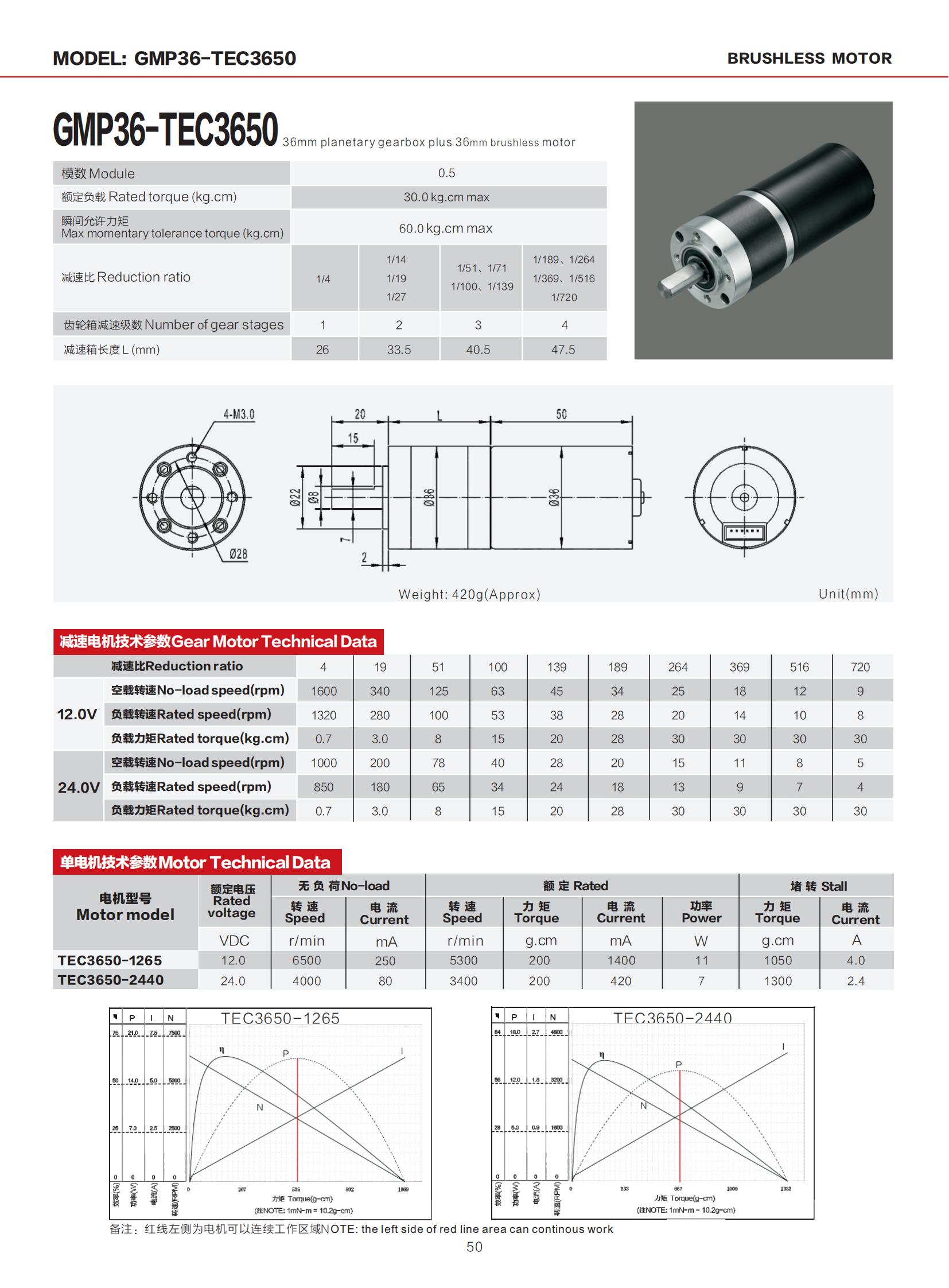
This article works through what actually changes in a real design, using three TT Motor units as reference points: the brushless planetary GMP36-TEC3650, the coreless planetary GMP12T-TDC1215, and the brushless worm gear TWG3246-TEC2430. TT Motor (Shenzhen) Industrial Co., Limited is a miniature DC motor manufacturer established in 2006, headquartered in Bao’an District, Shenzhen, with a manufacturing area of approximately 9,000 m² and more than 300 employees.
The Problem: A Gearbox Adds Interfaces, Not Just Ratio
Most designs start with a motor, not with a gearbox. A 12 V brushless motor running at a few thousand rpm cannot deliver the torque, or the low output speed, that a mechanism needs, so a gearbox is added downstream. The ratio is the easy part. The interfaces are the expensive part.
An external gearbox introduces six elements that do not exist in a bare motor datasheet:
- A coupling or adapter between motor shaft and gearbox input.
- A second bearing support that holds the gearbox input concentric with the motor shaft.
- A mounting structure that keeps both housings rigid relative to each other.
- A lubrication boundary between two separate products.
- A sealing boundary at the joint, plus a cavity where debris can collect.
- A tolerance stack-up that spans two suppliers and, usually, nobody’s single drawing.
Each item is a line in the design review and a candidate failure mode. Misalignment between motor shaft and gearbox input does not stay a dimensional issue: it converts into radial load on the motor bearing, first-stage gear noise, and wear that appears months into production rather than on the bench. The problem is not that an external gearbox is badly made — it is that the joint between two correctly made parts is where control is lost.
Industry Background: Why Integration Is Moving From Preference to Requirement
The commercial context explains the engineering shift. Grand View Research values the global brushless DC motor market at roughly USD 22.2 billion in 2025, and OEC reports that world trade in electric motors with an output below 37.5 W (HS 850110) reached USD 16.3 billion in 2024. Growth of that size is not coming from large industrial drives. It is coming from small, enclosed, battery-powered and precision equipment, where the motor package has to fit inside a product that is itself getting smaller.
Three application trends push designs toward the integrated geared motor:
- Low-speed positioning. Medical analyzers, pipetting equipment, lock mechanisms and adjustable supports run at single-digit to low-hundreds rpm. Reaching that speed through gearing is mandatory, and every interface between motor and load adds a backlash contribution measured at the output.
- Enclosure shrinkage. A separate coupling plus bearing block plus two housing walls commonly consumes more axial length than the gear train itself.
- Assembly economics. Every part that arrives pre-aligned and pre-tested is a station, an operator and an inspection step removed from the customer’s line.
This is why the choice between a brushless motor with an external gearbox and a dc brushless gear motor is rarely decided on paper specifications alone. It is decided on who owns the interfaces.
Detailed Solution: What Changes in a Real Design
1. Alignment moves inside the housing
In a motor-plus-gearbox design, shaft concentricity is a specification the buyer must create, measure and maintain. In an integrated unit, the motor shaft and the gearbox input are mated at assembly, on the manufacturer’s tooling, before the unit is tested. TT Motor applies 100% testing to production, so the alignment condition is verified per unit rather than sampled from a stack-up calculation.
What the designer must still control is the load on the output shaft. A planetary gear motor tolerates defined radial and axial loads at the output; a pulley or belt drive hanging off that shaft introduces loads the gearbox was never asked to carry. Integration removes the internal joint, not the external one.
2. Backlash is set by one gear train instead of a gear train plus a coupling
Backlash at the output is cumulative. In a separated design it includes coupling play, the first-stage mesh, and every subsequent stage. In an integrated geared motor the coupling contribution disappears, but stage count still governs the total: each additional reduction stage adds another mesh.
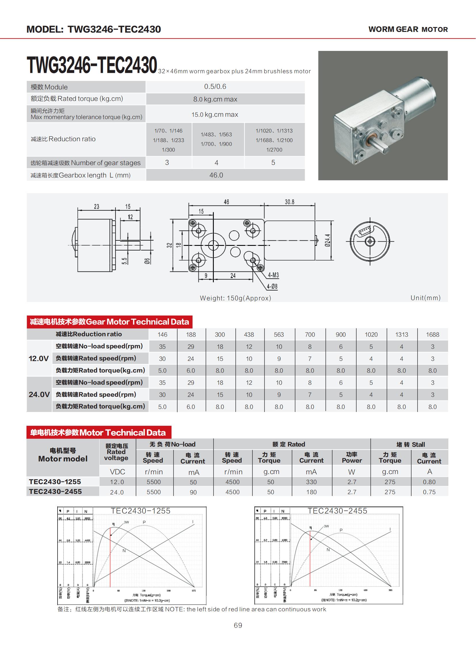
The published stage counts make this concrete. The GMP36-TEC3650 is available in 1, 2, 3 or 4 gear stages; the GMP12T-TDC1215 in 1, 2, 3 or 4 stages; the TWG3246-TEC2430 in 3, 4 or 5 stages. A four-stage planetary and a three-stage worm are not interchangeable on backlash, even when their rated torque looks similar — they solve different problems.
3. Compactness is measured at the output shaft, not the motor body
Gearbox length is the dimension that decides whether a design fits. In the TT Motor range the gearbox length is 14.9 / 19.7 / 24.5 / 29.3 mm for the GMP12T-TDC1215 across its 1–4 stages, 26 / 33.5 / 40.5 / 47.5 mm for the GMP36-TEC3650, and 46 mm for the TWG3246-TEC2430.
Those figures are the complete reduction package. An external gearbox adds its own input bearing housing and the coupling length on top of the gear train, so the comparable axial figure for a separated design is larger than the gearbox length alone. For miniature platforms the difference is decisive: the GM12-N20VA spur gear motor, for example, carries its gearbox in 9 mm or 12 mm, which is only achievable because the gear train and motor are designed as one envelope.
4. Sealing and lubrication have a single boundary
In a separated design there are two sealing boundaries and a joint cavity between them. Lubricant can migrate from the gearbox toward the motor, and ingress at the joint reaches the coupling before it reaches anything that is documented. In an integrated geared motor there is one housing, one lubricant specification and one sealing interface to validate.
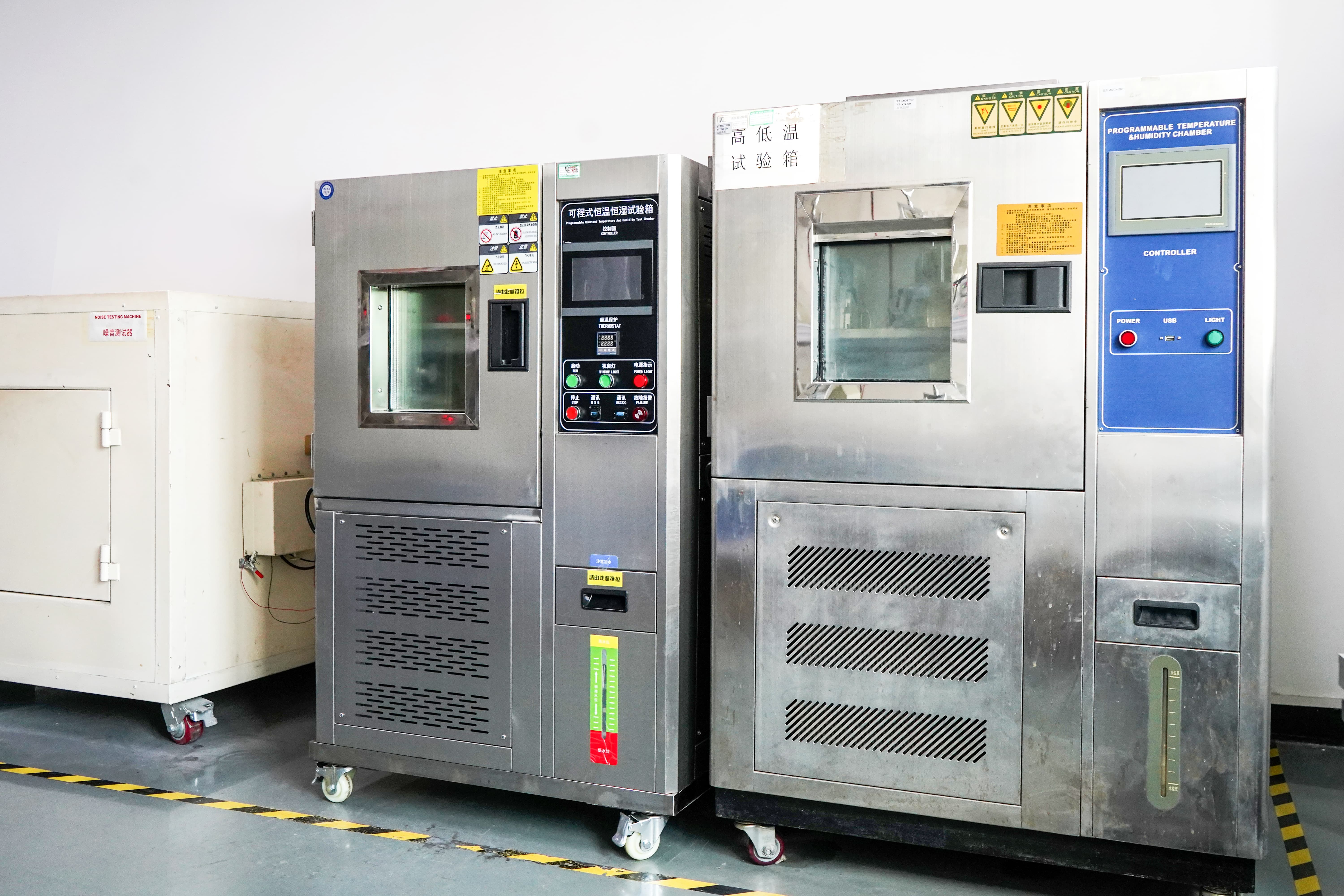
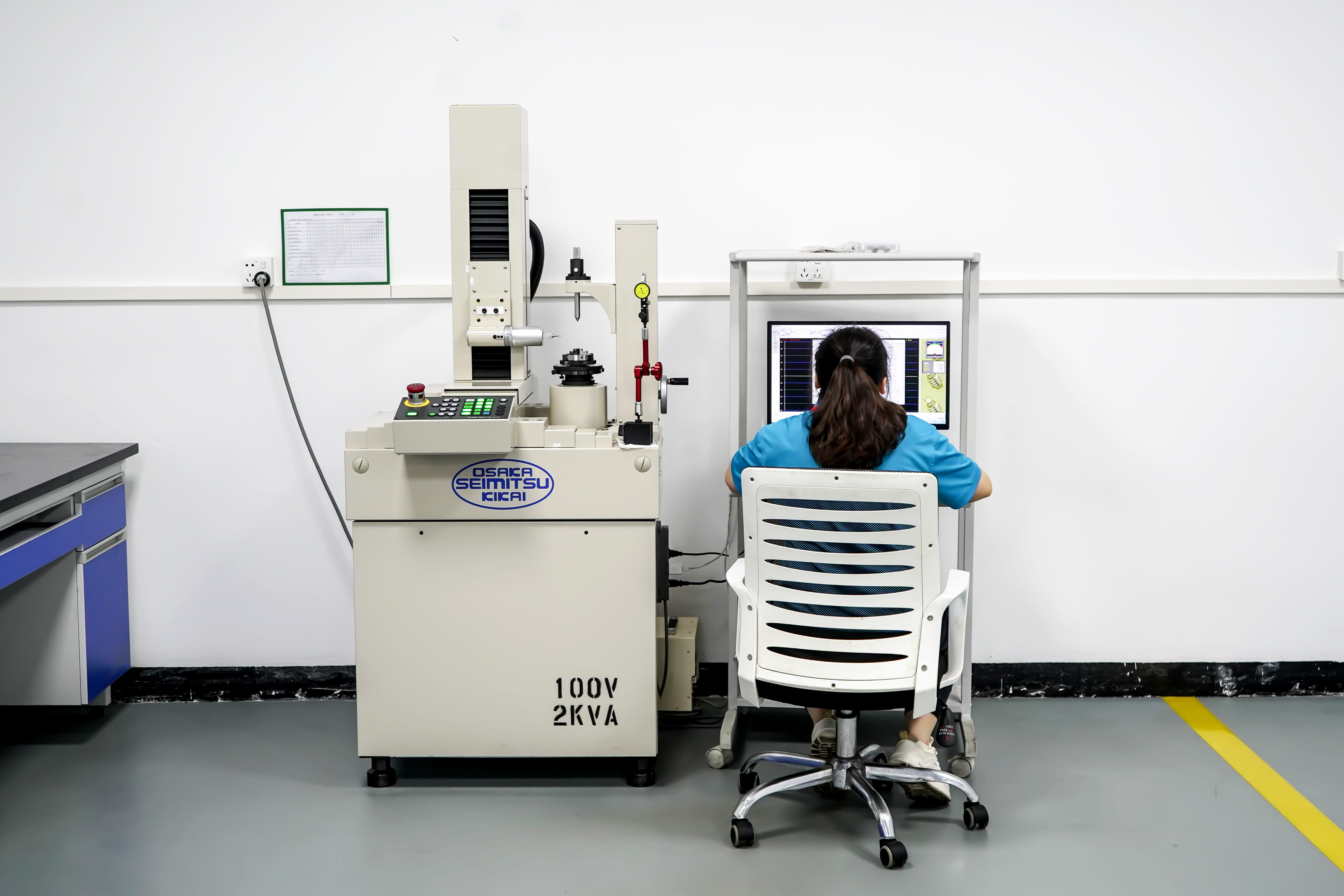
Validation is where the difference becomes auditable. TT Motor’s factory testing equipment includes a temperature and humidity chamber and motor life testing systems, which allow the assembled unit — not the bare motor — to be exercised as the product that ships.
5. Responsibility and documentation consolidate
An integrated unit means one purchase order, one incoming inspection, one warranty conversation and one document set scoped to what is delivered. That is not an administrative detail. When a RoHS report covers “DC gear motor, including GMP36-TEC3650 and related series models”, the certificate matches the part in the machine. When motor and gearbox come from two suppliers, each document covers only half the assembly.
Planetary, Coreless Planetary or Worm: Which Integrated Architecture Fits
Once the decision to integrate is made, the remaining question is which gear architecture matches the motion requirement. Three TT Motor units illustrate the trade-offs.
GMP36-TEC3650 — brushless planetary for torque and controllability
The GMP36-TEC3650 is a brushless planetary gear motor built on a 0.5 module gear train, with a rated torque of 30.0 kg.cm maximum, 1 to 4 gear stages, DC 12V–24V rated voltage, and an output speed range of 4–1600 rpm. Materials are stainless steel, copper and iron. Its intended applications are robots, medical devices, industrial automation equipment and intelligent logistics equipment — duties where a high torque planetary motor has to start and stop repeatedly without brush wear becoming the life limit.
GMP12T-TDC1215 — coreless planetary for response speed in a small envelope
The GMP12T-TDC1215 is a coreless gear motor with a 0.2 module gear train, 1 to 4 stages, a rated torque of 2 kg.cm maximum, DC 4.5V–12V rated voltage and an output speed range of 8–5000 rpm. Coreless rotors have a very small moment of inertia, which is why the platform is used where the controller must issue a stop command and have the mechanism actually stop: a large-inertia rotor keeps turning after the command and produces overshoot. Typical applications are medical equipment, precision robots, high-end consumer electronics and micro sensors.
TWG3246-TEC2430 — worm gear for very low output speed in a short axial length
The TWG3246-TEC2430 is a brushless worm gear motor with a 0.5/0.6 module gear train, 3, 4 or 5 stages, a rated torque of 8.0 kg.cm maximum, DC 12V–24V rated voltage and an output speed range of 3–35 rpm. The gearbox length is 46 mm. Its applications are miniature medical devices, precision automated instruments and electrically adjustable supports — mechanisms where the output must move slowly and hold position, and where the reduction has to happen within a fixed axial budget.
For comparison, two brushed platforms show where the integrated approach sits in the wider range: the GM37-555PM dc spur gear motor delivers 8.0 kg.cm maximum at 5–800 rpm on DC 12V–24V with 2 to 6 stages and a 19–29 mm gearbox, while the GM12-N20VA spur gear motor delivers 0.5 kg.cm maximum at 12–1450 rpm on 2.4V/5V with a 9 or 12 mm gearbox. Both are integrated geared motors in exactly the sense discussed here — the brushed dc motor and its spur stage are one assembly.
The Risk Question: What an Integrated Geared Motor Actually Removes
The practical question buyers ask is narrower than the engineering one: does specifying a geared motor instead of a brushless motor plus external gearbox reduce project risk, or simply move it? It reduces five specific risks and adds two constraints.
Risks that leave the project:
- Tolerance stack-up ownership. The interface between motor and gearbox is designed, assembled and tested by one supplier rather than negotiated across two drawings.
- Joint contamination and lubricant migration. One housing means one ingress path to validate.
- Double validation cost. Backlash is measured once, at the output, on the unit that ships — not inferred from a motor datasheet plus a gearbox datasheet.
- Fragmented documentation. Model-level RoHS reports and a quality management system certificate cover the delivered assembly rather than a component of it.
- Split root-cause analysis. If the output stalls, there is one party responsible for the gear train, the bearing support and the seal.
Constraints the project accepts:
- The ratio is fixed at order. Changing gear stages means a new part number, not a field swap of a gearbox.
- The gear stage is not field-serviceable. For mechanisms that must be repaired in place, a replaceable external gearbox still has a role.
- The envelope is the manufacturer’s. Custom shafts, encoders, gearboxes, voltage, logo and speed are available through OEM/ODM work, but the internal architecture is not open to modification.
Step-by-Step Breakdown: Converting a Motor + Gearbox Design
Step 1 — Fix the output requirement first
Write down output torque, output speed, duty cycle, voltage rail and mounting pattern before looking at any catalogue. Everything downstream is a consequence of these five numbers.
Step 2 — Map the requirement onto stage count
Use published stage counts and torque ceilings rather than estimating. For example: 30.0 kg.cm maximum with 4–1600 rpm on the GMP36-TEC3650; 2 kg.cm maximum with 8–5000 rpm on the GMP12T-TDC1215; 8.0 kg.cm maximum with 3–35 rpm on the TWG3246-TEC2430. If the required speed falls below what a three-stage unit reaches, the answer is a different architecture, not a longer gear train.
Step 3 — Decide the mechanical interface
Shaft geometry, encoder fitment and mounting are where customization is normally needed; TT Motor lists shaft, encoder, gearbox, voltage, logo and speed among the customizable parameters under its OEM/ODM model.
Step 4 — Fix the sealing and lubrication boundary in the drawing
State where the seal sits and which lubricant is approved. In an integrated unit this is a single callout; in a separated design it is a joint specification that often goes unwritten.
Step 5 — Validate backlash at the output, under load
Measure at the output shaft with the intended load attached. A backlash figure taken at the motor shaft, or taken unloaded, will not describe the mechanism the customer experiences.
Step 6 — Lock the document set to the delivered model
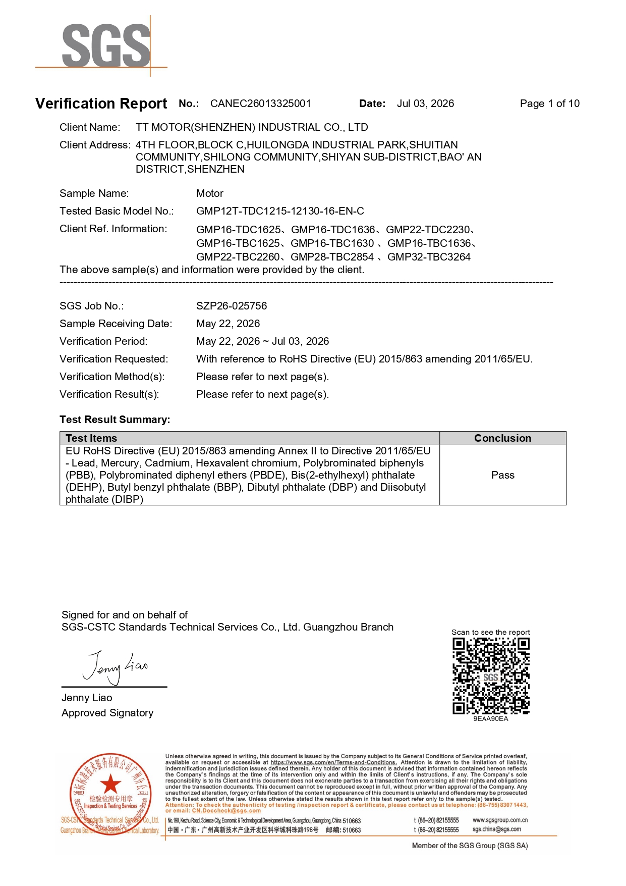
Match certificates to the exact model. TT Motor holds SGS RoHS compliance test reports for GMP36-TEC3650 (CANEC26013325501, issued 2026-04-10), GMP12T-TDC1215 (CANEC26013325001, issued 2026-07-03) and TWG3246-TEC2430 (CANEC26013326101, issued 2026-06-24), each with reference to RoHS Directive (EU) 2015/863. The quality management system is certified to ISO 9001:2015 under certificate F02926Q00865R402, issued by DCI and valid to 2029-08-21, with a scope covering R&D and manufacture of micromotors including DC gear motors and DC brushless motors.
Use Cases: Where the Integrated Version Wins in Practice
Logistics and sorting equipment
A US logistics equipment company uses the GMP36-TEC3650 and GM37-555PM to drive conveyor and sorting mechanisms. The project covers 1,000 units and has been in operation for three years or more, with stable operation under frequent start-stop and load changes. The engineering reason is straightforward: a joint between motor and gearbox is exactly where repeated reversing loads do the most damage, so removing that joint removes the wear path.
Smart lock mechanisms
A US smart lock manufacturer has supplied 5,000 to 50,000 units per year for five years or more, using the GM12-N20VA, GMP12T-TDC1215 and TWG3246-TEC2430 across lock body and transmission functions. In a lock, axial length is the constraint and noise is the acceptance criterion — both are properties of the assembled unit, not of a motor alone.
Dental and precision instruments
A Japanese dental instrument manufacturer uses the GMP12T-TDC1215 to drive a micro positioning and adjustment mechanism, at 500–2,000 units per year over a project duration of three to five years. The reported result is rapid response and improved equipment control precision, with low inertia, fast response and high power density as the key characteristics. Here the integrated coreless planetary package is what makes the response time achievable at that size.
Medical pumps
A UK medical device manufacturer uses the TWG3246-TEC2430, GMP12T-TDC1215 and GMP36-TEC3650 to drive medical pumps at 500–2,000 units per year for three years or more, maintaining stable output under long-term running and reducing equipment maintenance frequency. Low noise, low vibration and long lifespan are properties that depend on the gear mesh being sealed, lubricated and aligned as one assembly.
Comparison Table
The first table compares the two design approaches on the attributes that change. The second summarises the published parameters of the reference models.
| Design attribute | Integrated geared motor | Motor + external gearbox |
|---|---|---|
| Motor-to-gearbox alignment | Set and verified by the manufacturer at assembly | Created and maintained by the machine designer via coupling and bearing support |
| Backlash contributors at output | Gear train only; rises with stage count | Gear train plus coupling play plus adapter fit |
| Axial length | Gearbox length as published, e.g. 14.9–29.3 mm (GMP12T-TDC1215), 26–47.5 mm (GMP36-TEC3650), 46 mm (TWG3246-TEC2430) | Gear train plus coupling plus input bearing housing |
| Sealing boundary | One housing, one seal to validate | Two product seals plus a joint cavity |
| Lubrication | Single approved lubricant, factory-controlled | Two lubricants, migration path at the joint |
| Incoming inspection | One part number, one inspection | Two part numbers plus assembly step |
| Ratio flexibility after order | Fixed; change requires a new model | Gearbox can be swapped independently |
| Field serviceability of gear stage | Not serviceable in the field | Replaceable by the user |
| Documentation scope | Certificate covers the delivered geared motor model | Each certificate covers only its own component |
| Model | Architecture | Module | Gear stages | Gearbox length | Rated torque (max) | Speed range | Rated voltage |
|---|---|---|---|---|---|---|---|
| GMP36-TEC3650 | Brushless planetary gear motor | 0.5 | 1 / 2 / 3 / 4 | 26 / 33.5 / 40.5 / 47.5 mm | 30.0 kg.cm | 4–1600 rpm | DC 12V–24V |
| GMP12T-TDC1215 | DC brush coreless gear motor | 0.2 | 1 / 2 / 3 / 4 | 14.9 / 19.7 / 24.5 / 29.3 mm | 2 kg.cm | 8–5000 rpm | DC 4.5V–12V |
| TWG3246-TEC2430 | DC brushless worm gear motor | 0.5 / 0.6 | 3 / 4 / 5 | 46 mm | 8.0 kg.cm | 3–35 rpm | DC 12V–24V |
| GM37-555PM | DC brush spur gear motor | 0.5 / 0.6 | 2 / 3 / 4 / 5 / 6 | 19 / 21.5 / 24 / 26.5 / 29 mm | 8.0 kg.cm | 5–800 rpm | DC 12V–24V |
| GM12-N20VA | DC spur gear motor | 0.15 | 2 / 4 / 5 / 7 | 9 / 12 mm | 0.5 kg.cm | 12–1450 rpm | 2.4V / 5V |
FAQ
Are integrated geared motors supplied with RoHS and ISO documentation?
Yes, at model level. TT Motor holds SGS RoHS compliance test reports for GMP36-TEC3650 (CANEC26013325501, issued 2026-04-10), GMP12T-TDC1215 (CANEC26013325001, issued 2026-07-03) and TWG3246-TEC2430 (CANEC26013326101, issued 2026-06-24), each with reference to RoHS Directive (EU) 2015/863 amending 2011/65/EU. The quality management system is certified to ISO 9001:2015 (GB/T 19001-2016) under certificate F02926Q00865R402 issued by DCI, valid to 2029-08-21, with a scope covering R&D and manufacture of micromotors including DC gear motors and DC brushless motors. Because the reports are scoped to the geared motor series rather than to a bare motor, the document matches the unit that is installed.
Can an integrated geared motor be customized, or does integration limit options?
Integration limits the internal architecture, not the external interface. TT Motor works under an OEM/ODM model with customization available on shaft, encoder, gearbox, voltage, logo and speed, supported by a 35-engineer R&D team. Production uses 100% testing, and monthly capacity is 800,000 pieces. What cannot be changed is the internal gear train design of a catalogue model; ratio changes are handled by selecting a different stage count or model.
Does a geared motor cost more than buying a motor and gearbox separately?
Unit price is not the right comparison, and no responsible supplier quotes it in isolation. The quote for an integrated geared motor depends on model, gear stage count, rated voltage, shaft and encoder customization, and order volume. TT Motor’s minimum order quantity is 2 pieces, so an evaluation build does not require a production commitment. The relevant comparison is total cost of ownership: an integrated unit removes a coupling, a bearing support, an assembly station, an alignment inspection and a second document set, while a separated design keeps two part numbers and two warranty paths. Request a configuration-specific quotation before comparing the two approaches on price.
How should a geared motor sample be validated before release?
Validate the assembled unit, not the motor alone. Measure backlash at the output shaft under the intended load, run the duty cycle the mechanism will actually see, and confirm the sealing boundary with an environmental check. TT Motor produces samples in 15–25 days and applies 100% testing to production units. Compare the sample against the motor-plus-gearbox baseline on the same test bench so the difference in backlash, noise and axial length is measured rather than assumed.
What are the sample and bulk lead times?
Standard delivery time is 15–25 days for samples and 30–45 days for bulk orders, with monthly production capacity of 800,000 pieces. Products are exported to the EU, US and East Asia markets, and after-sales technical support is provided remotely. To start an evaluation, send the output torque, speed, voltage and mounting requirement to sales26@ttmotor.com or contact Sally Su on +86 180-0299-3379 for a sample and quotation.
Conclusion
The shift from a brushless motor plus external gearbox to an integrated geared motor is not a purchasing shortcut. It relocates four engineering problems — alignment, backlash accumulation, axial packaging and sealing — from a joint the designer must specify to a housing the manufacturer assembles and tests. What the designer keeps is the output definition, and that is the part that should carry the engineering attention.
The three reference units show how the architecture decision follows the motion requirement rather than the other way round: GMP36-TEC3650 for high torque planetary duty up to 30.0 kg.cm, GMP12T-TDC1215 for fast, low-inertia response down to a 14.9 mm gearbox, and TWG3246-TEC2430 for 3–35 rpm in a 46 mm worm package. Choose the architecture, then decide whether the interface belongs on your drawing or inside the supplier’s housing.
Next Step: Test the Integrated Version Against Your Current Design
Send the output torque, speed, duty cycle and mounting pattern of your existing motor-plus-gearbox assembly. TT Motor will match it to an integrated geared motor configuration, confirm the gear stage count, and quote samples with model-level RoHS documentation.
Email: sales26@ttmotor.com | Tel: +86 180-0299-3379 | Website: www.ttmotor.com
Download the product catalogue: TT Motor exhibition catalogue (PDF)

Have Questions or Need More Details?
Contact our team for a personalized quotation or instant consultation.
Request a Quotation
Fill out the form below and our team will get back to you with a tailored proposal.
WhatsApp Direct Chat
Prefer to chat in real-time? Message us on WhatsApp for instant assistance & quick answers.
- Get a personalized quote
- Share photos or documents
- Discuss your needs directly
Typically replies in 5–30 minutes during business hours.