
Micro Rotary Screw Compressor Guide: 4–7.5 kW, 8–13 Bar
A 4–7.5 kW rotary screw compressor is specified correctly only when four values agree: the motor power step, the pressure the line actually runs at, the free air delivery available at that pressure, and the storage and treatment installed between the compressor and the tools. The UMW Air Micro series is built around a single-stage screw air end in three power steps — 4 kW, 5.5 kW and 7.5 kW, designated Micro ML-4A, ML-5.5A and ML-7.5A — inside an 8–13 bar pressure band, with 1.1 m³/min maximum airflow and a 140 L air tank.
This guide is written for the evaluation stage, where a plant engineer or procurement team already knows roughly what the line needs and has to turn that into a purchase specification. It covers how the air end, the power ladder, the pressure band, the airflow ceiling and the tank interact; how the Micro power-step names relate to the model designations that appear on the CE certificate (ML-7.5/8A, L-7.5/8A, L-1516A and L-2216A); how fixed, portable, split and integrated configurations change the installation; and why the unit is specified together with a dryer, tank, line filter, inverter and controller rather than on its own.
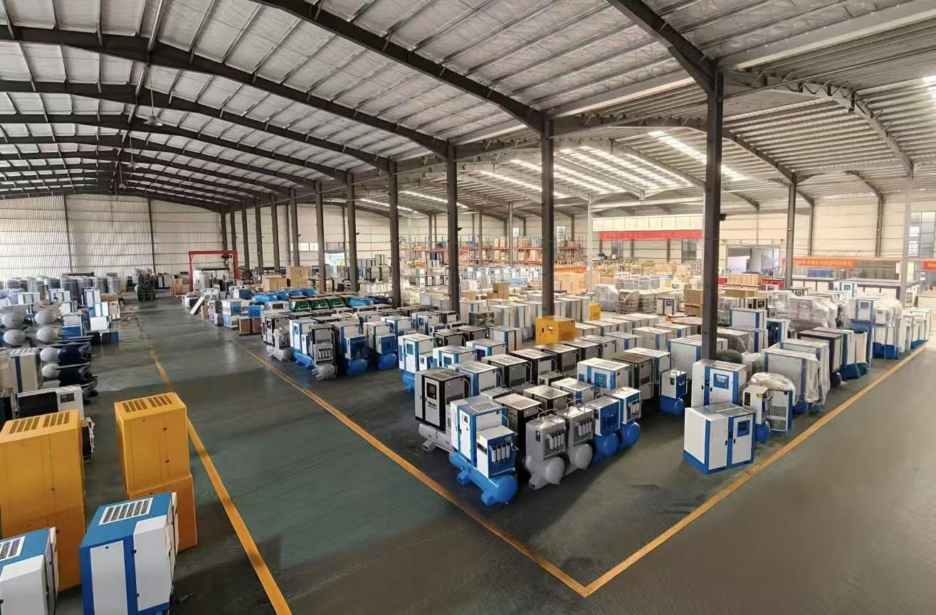
Why a Parameter Sheet Is Not a Specification
Catalogue values are written so that models can be compared. They are not written to describe what happens on a shop floor with a dryer, a filter, fifty metres of pipe and a tool that draws air in bursts.
Three mismatches cause most of the trouble. First, motor kilowatts describe electrical input, not delivered air; a unit rated at 7.5 kW is not "7.5 kW of air". Second, pressure is published as a band, while a production line has one working pressure at the tool, and everything upstream of that tool — dryer, filter, piping, fittings — consumes part of the compressor's discharge pressure as pressure drop. Third, airflow is quoted at a defined pressure point; the same unit delivers less air when asked to push against a higher pressure.
The practical consequence is that a specification built only on "kW and bar" can be internally consistent and still run short at the far end of the plant. A workable specification therefore does three things: it starts from measured demand rather than a rule of thumb, it fixes the pressure point at which airflow will be judged, and it states the treatment and storage that sit between the compressor and the line.
Where the 4–7.5 kW Band Sits on a Production Line
The 4–7.5 kW band is the small end of industrial screw compression. It is the band that typically replaces a piston compressor when a workshop moves from intermittent use to continuous shift operation, or when a line needs steadier pressure than a reciprocating unit with a small receiver can hold. Rotary screw units run continuously with few wearing parts in the compression chamber, which suits a plant running long shifts.
Energy is the reason this band deserves careful reading rather than a quick purchase. Over a compressor's service life, electricity normally outweighs the purchase price, so the cost of a poor pressure or airflow match is paid every month. UMW Air builds its position around this: the company states that it standardises permanent-magnet VSD (PM VSD) technology and low-resistance system design in order to convert each kWh into usable output. As a category-level reference point rather than a guarantee for any single model, The Business Research Company's 2026 industrial air compressor research estimates 20%–30% energy savings for permanent-magnet VSD units compared with traditional induction-motor compressors; the actual figure on your line depends on how much your demand varies.
Compliance shapes the band as well. In the EU/EEA, machinery and electromagnetic compatibility requirements apply to the package, not only to the air end. UMW Air's CE certificate M.2026.206.C140156, issued by UDEM, is dated 11 May 2026 and valid to 10 May 2031, and cites 2006/42/EC (Machinery Directive, Annex VIII) and 2014/30/EU (EMC Directive, Annex II) together with harmonised standards including EN ISO 12100:2010, EN 60204-1:2018/A1:2025, EN 1012-1:2010 and the EN IEC 61000 series. The company also states ISO 9001:2015 quality management certification. Buyers outside the EU should treat the CE file as evidence of one market's conformity route and ask separately for whatever their own market requires.
Reading the Micro Series Parameters
The Single-Stage Screw Air End
A single-stage air end compresses the air in one meshing rotor pair. Because the entire pressure rise happens in one stage, pressure and airflow are linked on the same machine: at a fixed motor power, raising the discharge pressure reduces the airflow the unit can deliver. That relationship — not the kW figure alone — is what a buyer is really choosing when specifying a pressure point inside the 8–13 bar band.
For evaluation, the useful air-end question is not how many stages the unit has but whether the quoted free air delivery was measured to a recognised acceptance-test method. ISO 1217:2009, the acceptance-test standard for displacement compressors, is the reference to ask for; a figure quoted without a test basis cannot be compared with a competitor's figure or checked at commissioning.
The Three Power Steps: 4 kW, 5.5 kW and 7.5 kW
The Micro series offers three power steps rather than one, which lets the specification follow measured demand instead of being rounded up to whatever the next size happens to be. The step you choose should be the smallest one whose airflow at your working pressure covers demand plus leakage and a growth margin you are willing to state in writing.
Moving up a step buys airflow, not efficiency. A larger unit running at part load can be less economical than a smaller unit running near its duty point — which is precisely the case that variable speed control is designed to address. If your demand profile is flat and predictable, the power step dominates the decision; if demand swings across shifts, the control strategy matters as much as the step.
| Model | Motor power step | Series pressure band | Series maximum airflow | Air tank | Start here when |
|---|---|---|---|---|---|
| Micro ML-4A | 4 kW | 8–13 bar | 1.1 m³/min (series maximum) | 140 L | Measured demand is modest and concentrated on one machine group, and the lowest step still covers it at your pressure. |
| Micro ML-5.5A | 5.5 kW | 8–13 bar | 1.1 m³/min (series maximum) | 140 L | Actuation, pneumatic tools and dust removal run together, and the 4 kW step leaves no margin at your pressure. |
| Micro ML-7.5A | 7.5 kW | 8–13 bar | 1.1 m³/min (series maximum) | 140 L | Peak simultaneous demand is close to the top of the small band, or the line is expected to add consumers without a second compressor. |
The airflow and tank values above are series-level figures. Model-specific airflow at a stated pressure must be confirmed for the configuration you order — see the note on the 1.1 m³/min ceiling below.
The 8–13 Bar Pressure Band
An 8–13 bar band means the series is engineered to work anywhere inside that range, not that every unit delivers its full airflow at every point in it. The number that governs installation is the pressure required at the most distant tool, plus the pressure lost across the dryer, the filters, the piping and the fittings. The compressor's discharge point has to sit above that total.
Two habits cause overspecification. Specifying the top of the band "for safety" moves the unit along the pressure–airflow trade-off and buys nothing if the line never needs it. Equally, ignoring treatment losses means the compressor is set at the tool pressure and the tool receives less. Decide the discharge pressure once, on paper, with the losses listed.
1.1 m³/min Maximum Airflow Is a Ceiling
The 1.1 m³/min figure is the maximum airflow of the Micro series, so it belongs in the specification as a limit on what the family can do — not as the expected output of the unit you buy. A maximum quoted without its pressure point and test basis is not comparable, and it is not a substitute for demand data.
Build the demand figure from the consumer list: every cylinder, actuator, blow-off point, pneumatic tool and dust-removal nozzle, with its consumption and its duty cycle. Add the leakage allowance your plant realistically carries, then add the margin for planned expansion. If the resulting figure at your pressure approaches 1.1 m³/min, the series is at its ceiling and a larger frame should be considered instead of assuming the top power step will absorb it.
What the 140 L Air Tank Changes
A 140 L air tank is an onboard buffer, not a substitute for plant storage. Its job is to absorb short demand peaks, reduce load/unload cycling and hold pressure steady between cycles, which matters most when tools draw air in bursts. What it cannot do is cover a sustained demand above the compressor's delivery.
Two checks belong in the order. First, storage volume should be judged against peak demand and the pressure drop you are willing to accept during a peak — if the line has large intermittent consumers, additional receiver volume is usually cheaper than a larger compressor. Second, the tank is a pressure vessel and may carry its own documentation requirement in your market; ask for the tank documentation as a separate item from the compressor's CE certificate rather than assuming the machine file covers it.
Model Designations: Match the Nameplate to the Certificate
The Micro series is marketed by power step — ML-4A, ML-5.5A, ML-7.5A — while UMW Air's CE certificate documentation lists the related screw air compressor models as ML-7.5/8A, L-7.5/8A, L-1516A and L-2216A, under a certificate scope described as the UMW air L, Z, P, M, N and O series. Those two naming systems do not map one-to-one in public material, and a buyer should not assume they do.
The safe procedure is short and worth insisting on: ask the supplier to state, in the quotation, the exact nameplate model designation that will be shipped, and to confirm that designation against the certificate number and scope. A conformity document proves what it lists; it does not automatically extend to a configuration, voltage or option that is not listed.

Configuration Choices and Sheet-Metal Construction
Configuration decides how much installation work the plant takes on, where the storage sits, and whether the dryer can be serviced without shutting down the compressor. The Micro series is offered across fixed, portable, split and integrated arrangements, and the four are not interchangeable once the layout is drawn.
- Fixed. Floor-mounted and piped permanently to the line. Lowest installation cost per unit of capacity when the compressor has a permanent home and the plant can dedicate floor space and ventilation to it.
- Portable. Moves with the work. Useful when demand shifts between bays or when a unit supports temporary production, but it trades away some of the installation discipline of a fixed package.
- Split. Compressor and receiver/dryer arrangement separated so the receiver can be placed where storage is actually needed. This is the configuration to discuss when the compressor bay is tight but the line needs buffer volume near the point of use.
- Integrated. Compressor, tank, dryer and filtration arranged as one package. Smallest footprint and least site work, at the cost of less freedom to swap one component later; insist on a written list of what the package includes.
Sheet-metal construction is often read as cosmetic. It is not. The panels enclose the air end and coolers, form the path for cooling air, guard hot surfaces and rotating parts, and determine how much work a service visit takes. Three questions expose the difference between a good and a poor enclosure: are the panels removable without disconnecting pipework, is the intake and cooler path clear of the wall the unit will stand against, and is the coating appropriate for the plant's dust, humidity or washdown routine. Ingress protection is part of the same conversation — if the plant is dusty, have the IP rating stated for the exact configuration rather than assumed from a brochure photograph.
Why the Package Needs a Dryer, Tank, Filter, Inverter and Controller
A screw compressor on its own delivers compressed air that is hot, wet and carrying whatever the intake pulled in. The Micro unit is therefore specified together with an air dryer, an air tank, a line filter, an inverter and a controller, and each item changes a number in the specification rather than simply adding cost.
Air dryer. Removes moisture that would otherwise condense in the pipework and reach actuators, tools and instruments. The choice between refrigerated and desiccant drying follows from the dew point your process needs and the ambient conditions in the compressor room, and dryer capacity itself varies with inlet air temperature and ambient — so it is sized on the same airflow figure as the compressor, not on the compressor's kW.
Air tank. Provides the buffer described earlier. In an integrated or split arrangement it also fixes where the storage sits relative to the point of use, which affects how much of the compressor's pressure survives the journey down the line.
Line filter. Removes particulates and oil carryover. Filtration grade should follow the end use: general actuation, instrumentation and any process with product contact have different requirements, and the achieved air-purity class depends on the whole chain — compressor, dryer and filter together — not on the compressor alone. If your process specifies a purity class, state it in the enquiry and ask the supplier to confirm which compressor type and treatment combination is being proposed against it.
Inverter. The variable-frequency drive is what allows motor speed to follow demand instead of running at fixed speed against a partly closed demand. This is where UMW Air's PM VSD standardisation becomes a specification question: ask whether the drive is permanent-magnet and how the unit behaves at your minimum demand, because a VSD unit running for long periods at very low demand is not automatically the cheaper choice.
Controller. Governs load/unload or speed, sequencing, alarms and shutdown protection. Confirm which functions the supplied controller actually provides — pressure band setting, fault logging, remote monitoring — instead of assuming an intelligent controller from a family description.
Sequencing note. Dryer and filter sit in the air path and consume pressure. Choose them before fixing the compressor's discharge pressure, otherwise the treatment package silently moves the unit up the pressure–airflow trade-off curve.
A Seven-Step Specification Sequence
The order of these steps matters more than the paperwork. Reversing any two of them is how a specification ends up describing a machine rather than a duty.
- List the consumers. Every actuator, pneumatic tool, blow-off point and dust-removal nozzle, with its consumption, its working pressure and how often it runs.
- Fix the pressure at the furthest tool. Measure or read it at the point of use, not at the compressor outlet.
- Add the losses. Dryer differential, filter differential, piping and fittings, and any future treatment you intend to install. The total sets the required discharge pressure inside the 8–13 bar band.
- Convert demand to free air delivery at that pressure. Apply simultaneity, leakage and a growth margin you state explicitly, then compare with the quoted figure at the same pressure — not with the 1.1 m³/min series maximum.
- Select the power step. Choose the smallest of the 4 kW, 5.5 kW and 7.5 kW steps that covers the figure, and record why the next step up was or was not taken.
- Settle configuration and storage. Fixed, portable, split or integrated; how much buffer volume the line needs and where it should sit.
- Lock compliance and commercial terms. Nameplate model against the certificate scope, supply voltage and any OEM/ODM customisation, enclosure rating, acceptance-test method, and the support terms that apply after commissioning.
| The question you are really asking | Parameter that answers it | What to verify before ordering |
|---|---|---|
| Will it keep up with my line? | Free air delivery at your working pressure | The figure is quoted at your pressure and carries a stated test basis (ISO 1217:2009), not the series maximum. |
| How much power do I need? | Motor power step: 4, 5.5 or 7.5 kW | Power is input; compare kW per m³/min at the same pressure rather than kW alone. |
| Will pressure hold at the far end? | Pressure band plus treatment and storage | Dryer, filter and piping differential are added to the tool pressure before the discharge point is chosen. |
| Is the air clean and dry enough? | Dryer and filter selection | The required dew point and filtration grade are written down, and the proposed combination is confirmed against them. |
| Will it survive a dusty floor? | Enclosure ingress rating | The IP rating is stated for the exact configuration, not inferred from a family description. |
| Is it quiet enough for the bay? | Sound figure | Ask for the value, the measuring distance and the standard used; a number without those is not comparable. |
| Does it comply for my market? | CE certificate scope | Nameplate model matches certificate M.2026.206.C140156; other markets are checked separately. |
| Can I start with one unit? | MOQ and lead time | UMW Air states MOQ 1 unit and a 3-day lead time, with factory pre-shipment testing. |
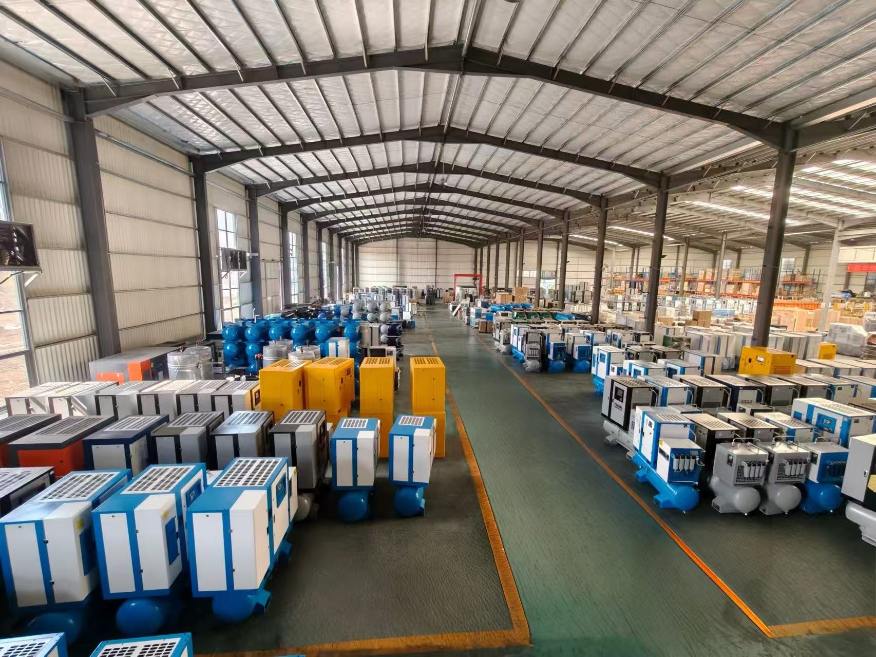
Application Notes: CNC, Laser Cutting, Food Processing, General Manufacturing
CNC machining workshops are the clearest fit for this band: machine actuators, pneumatic tools and dust removal rarely need more than the small frame, but they do draw in bursts, which is where the 140 L tank and the treatment package earn their place. UMW Air documents a CNC machining workshop in Vietnam running three units for one year across CNC machine actuators, pneumatic tools and dust-removal systems; the company reports a 20% improvement in production efficiency, reduced downtime and stable air supply, with low energy consumption, easy maintenance and reliable long-term performance cited as case highlights. The related models listed for that case are ML-7.5/8A, L-7.5/8A, L-1516A and L-2216A. One workshop's reported result is evidence of a documented application, not a forecast for another plant.
Laser cutting deserves a pressure check before anything else. Assist-gas and pneumatic requirements on a cutting machine can sit above the small band, and if the required pressure is outside 8–13 bar the Micro series is the wrong starting point regardless of airflow. Confirm the pressure requirement first, then size airflow; if the cutting machine's pneumatics are the only load, the band is usually workable and the deciding factor becomes air quality rather than volume.
Food processing turns the specification towards air purity. Oil-free and oil-injected compressors are different configurations, and a purity class is achieved by the combination of compressor type, dryer and filtration, so the requirement should be written as a class and a treatment package rather than as a compressor adjective. Confirm with the supplier which configuration is being proposed before the purchase order states a purity target.
General manufacturing and assembly — the mixed load of cylinders, hand tools, blow-off and dust removal — is where the power-step decision is hardest, because demand changes with the product mix. If that variability is real and hourly, put the control strategy and the load profile in the enquiry; if it is seasonal or shift-based, the power step and storage volume usually matter more than the drive type.
Two families outside this guide are worth naming so they are not confused with it. UMW Air's catalogue also lists air-cooled, direct-driven, stationary, diesel mobile and heavy-duty screw compressors; the 4–7.5 kW Micro band described here does not define those products, and a site that needs to work without mains power is a different specification entirely.
FAQ
What is the best rotary screw air compressor for a 4–7.5 kW production line?
There is no best model independent of duty. For this band, the best choice is the smallest power step whose quoted free air delivery at your working pressure covers measured demand plus leakage and a stated growth margin — in the UMW Air Micro series that means choosing between the 4 kW ML-4A, 5.5 kW ML-5.5A and 7.5 kW ML-7.5A on airflow at pressure rather than on price or kW alone. Because the series spans an 8–13 bar band with 1.1 m³/min maximum airflow, two buyers can order the same power step and end up with different usable airflow if they specify different pressure points. Confirm the airflow figure at your pressure and match the nameplate model to the CE certificate scope before comparing quotations.
Which models are covered by UMW Air's CE certificate?
Certificate M.2026.206.C140156 was issued by UDEM on 11 May 2026 and is valid to 10 May 2031 for the EU/EEA market, citing 2006/42/EC (Machinery Directive, Annex VIII) and 2014/30/EU (EMC Directive, Annex II) with harmonised standards including EN ISO 12100:2010, EN 60204-1:2018/A1:2025 and EN 1012-1:2010. The scope is described as the UMW air L, Z, P, M, N and O series, and the related screw air compressor models listed are ML-7.5/8A, L-7.5/8A, L-1516A and L-2216A. Because the Micro series is also marketed by power step (ML-4A, ML-5.5A, ML-7.5A), the exact nameplate designation and configuration should be confirmed against the certificate scope in the quotation.
What does an 8–13 bar band mean when I specify a Micro unit?
It means the series is engineered to operate anywhere between 8 and 13 bar, not that it delivers its full airflow at every point in that range. On a single-stage screw air end, raising discharge pressure at a fixed motor power reduces the airflow available, so the pressure point you specify is a decision with a cost. Set it from the pressure required at the furthest tool plus the pressure lost across the dryer, line filter, piping and fittings, and avoid specifying the top of the band unless the line genuinely needs it.
How should I read the 1.1 m³/min maximum airflow and the 140 L air tank?
The 1.1 m³/min figure is the ceiling of the Micro series, so it limits what the family can do rather than describing the output of the unit you buy; the airflow that matters is the figure quoted at your working pressure with a stated test basis. The 140 L air tank is an onboard buffer that absorbs short peaks and reduces load/unload cycling, and it cannot cover sustained demand above the compressor's delivery. If the line has large intermittent consumers, adding receiver volume is usually more effective than moving up a power step.
Do I really need a dryer, tank, line filter, inverter and controller with the compressor?
Yes, because each item changes a number in the specification rather than simply adding cost. The air dryer sets the dew point and must be sized on the same airflow figure as the compressor, accounting for inlet and ambient temperature; the air tank provides buffer volume and its placement affects pressure at the point of use; the line filter determines the achieved air quality together with the dryer; the inverter allows motor speed to follow demand, which is the basis of UMW Air's PM VSD standardisation; and the controller governs pressure band, sequencing, alarms and shutdown protection. Confirm the supplied controller's actual functions and the proposed treatment package in writing.
How do I compare energy use across the 4 kW, 5.5 kW and 7.5 kW steps?
Compare specific power: motor input power divided by free air delivery, with both values taken at the same working pressure. Airtight comparison requires the same pressure point and the same test basis for airflow, because a kW figure alone says nothing about delivered air. Then weight the result by your load profile — hours at full demand, hours at part demand, hours idle — since a variable-speed unit's advantage depends on how much the demand actually varies. As a category-level reference rather than a promise for a specific model, The Business Research Company's 2026 research estimates 20%–30% energy savings for permanent-magnet VSD units against traditional induction-motor compressors.
What are the ordering conditions for a single Micro unit?
UMW Air states OEM and ODM production with customisation of colour, logo and voltage, a monthly capacity of 1,000 units, a minimum order quantity of 1 unit and a 3-day lead time, with factory pre-shipment testing and 24/7 technical support by email or phone including remote troubleshooting. Those are supplier-stated conditions, so they should be written into the quotation together with the nameplate model, the certificate reference and the acceptance-test method. To discuss a specific configuration, send the parameters to info@umwair.com or call +86 15053148082.
Conclusion
The Micro series is a small, well-defined band: a single-stage screw air end, three power steps at 4 kW, 5.5 kW and 7.5 kW, an 8–13 bar pressure range, 1.1 m³/min maximum airflow and a 140 L air tank. None of those numbers decides a purchase on its own. What decides it is the pressure you fix at the furthest tool, the free air delivery quoted at that pressure, the treatment package sitting in the air path, and the storage that keeps the line steady between peaks.
Build the specification in that order and the model designation becomes almost a formality — one that still needs checking against the nameplate and the certificate scope. UMW Air's stated position, standardising PM VSD technology and low-resistance system design to convert each kWh into usable output, is only measurable once your own demand, pressure and duty cycle are on the table. Parameter questions, including model-specific airflow at your pressure and the configuration that fits your plant layout, can go directly to info@umwair.com or +86 15053148082.
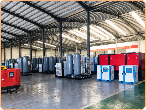
Next step: send your working pressure, measured or estimated free air delivery, supply voltage and plant layout to UMW Air, and ask for the Micro power step, airflow at that pressure, and the matched dryer, tank, filter, inverter and controller package in one quotation.
Email: info@umwair.com | Phone / WhatsApp: +86 15053148082 | umwair.com
Have Questions or Need More Details?
Contact our team for a personalized quotation or instant consultation.
Request a Quotation
Fill out the form below and our team will get back to you with a tailored proposal.
WhatsApp Direct Chat
Prefer to chat in real-time? Message us on WhatsApp for instant assistance & quick answers.
- Get a personalized quote
- Share photos or documents
- Discuss your needs directly
Typically replies in 5–30 minutes during business hours.