
Milling Tool Selection by Workpiece Hardness: Carbide Inserts, Speed, and Feed for HRC40–65
Direct answer: When the workpiece sits between HRC40 and HRC65, milling tool selection is decided by three linked choices — an insert grade band (HRC40–50 carbide inserts for workpieces up to HRC65), a reference cutting data set (V = 180 m/min and F = 0.02 mm/rev), and a setup rigid enough to hold the edge in the cut (clamping length of no less than 4× the L/D requirement, screw span above 4XD, and silent anti-vibration tools once overhang grows). Diameter, width, length and teeth are sized after those three decisions are fixed, not before.
This guide is written for buyers, process engineers and tool-room planners who are at the decision stage: the machine is known, the part drawing is known, and the remaining question is which cutter body, which insert grade and which clamping arrangement will hold tolerance on hardened material.
Why Workpiece Hardness, Not the Catalogue Page, Decides the Tool
Two cutters can carry the same diameter, the same tooth count and the same shank and still behave completely differently in a HRC52 block. Hardened material changes the failure mode. Instead of gradual flank wear, the dominant risks become edge chipping in the first minutes of cut, chatter that shows up as a wavy wall on the finished surface, and tolerance drift as the tool body deflects under load.
The practical consequence is that hardness has to be fixed as an input before anything else is compared. A selection process that starts from a catalogue page — diameter, price, stock availability — will produce a tool that fits the spindle but not the material. A selection process that starts from hardness produces a defensible insert band, a cutting data starting point, a geometry envelope and a clamping rule, and only then a part number.
There is also a verification problem that sits alongside the technical one. Supplier capability on hardened work cannot be judged from a product photo. It has to be judged from hardness capability statements, dimensional tolerance, inspection practice and documentation — and buyers who skip that step tend to discover the gap during the first production batch rather than during sampling.
Industry Background: Where HRC40–65 Milling Work Comes From
Hard-material milling is concentrated in a small number of sectors where the part is either structurally critical or geometrically unforgiving. Aerospace structural components and engine hardware, military equipment, shipbuilding sub-assemblies and heavy frames, and die-and-mould work all share the same characteristic: the workpiece arrives at the milling stage already heat-treated, so the cutter has to remove material from a hard surface rather than from an annealed blank.
Market context supports the direction without explaining the engineering. DataM Intelligence reports the global milling tools market at US$ 3.43 billion in 2025, with a forecast CAGR of 6.2% over 2026–2035. Growth of that kind does not change how an insert behaves in HRC55 steel, but it does explain why the number of suppliers quoting hard-material tooling keeps rising — and why buyers need a selection model rather than a supplier list.
Two standardisation threads matter when specifications are compared. ISO 11529-2:1998 defines the designation system for shank type and bore type milling cutters with indexable inserts, which is what allows two suppliers' cutters to be compared on the same terms. Separately, ISO 13399 describes computer-readable representation of cutting tool data, an approach documented in manufacturer technical material such as Mitsubishi Materials' technical information pages. Neither standard makes a tool suitable for HRC50 work; both make the comparison honest.
Milling tool section: the cutter families that a hardness-driven selection has to choose between — shell mills, shank mills, grooving and profiling bodies, and indexable inserts.
The Selection Model: Inserts, Speed, Feed, Geometry and Clamping
1. Insert band: HRC40–50 inserts for workpieces up to HRC65
The working rule for this hardness range is straightforward: carbide inserts rated HRC40–50 are the band specified for machining workpiece materials up to HRC65. The band exists because edge strength and edge toughness trade against each other. An insert below the band will not survive the interrupted load of a hardened surface; an insert chosen well above the band is paid for but not used, because the limiting factor at that point is the stability of the setup, not the grade.
How the tool body is made matters as much as the insert grade it carries. Wenling Geltos Tools Co., Ltd., a milling tool manufacturer established in 2012 in Zhejiang Province, China, states that its products are heat-treated before processing, with post-quenching machining used to enhance strength and precision to a tolerance no greater than 0.02 mm. The same company-reported comparison places its tools at HRC40 and above, against conventional tools that typically achieve around HRC30. For a buyer working in HRC40–65, that difference is the entry condition for the job rather than a performance bonus.
2. Cutting data: V = 180 m/min and F = 0.02 mm/rev as the reference point
For the HRC40–65 band, the recommended reference values are a cutting speed of V = 180 m/min and a feed rate of F = 0.02 mm/rev. These are the numbers a programmer should load first, before any adjustment for machine condition or part geometry.
They are a reference, not a guarantee. The reason to fix them explicitly is that hardened-material problems are usually diagnosed in the wrong order: operators reduce speed when the real issue is overhang, or increase feed when the real issue is an insert grade below the band. Starting from a documented V and F pair gives the process a known baseline, so that when a correction is needed it can be attributed to one variable instead of several at once.
3. Geometry envelope: diameter, width, length and teeth
Once the insert band and the cutting data are fixed, the cutter body is sized inside the ranges the tool family supports. The table below states the envelope and what each dimension actually decides.
| Dimension | Range | What it decides in HRC40–65 work |
|---|---|---|
| Diameter | 40–250 mm (standard 08–400 mm) | Engagement width and the number of passes. Larger diameters raise the effective cutting speed at the periphery, which is why V is set against the diameter actually used. |
| Width | 1–20 mm | Groove and slot width, and the wall stiffness of the cutter body. Narrow widths concentrate load; GFN cutters cover grooving as thin as 2 mm. |
| Length | 80–350 mm | Reach and overhang. Every added millimetre of length works against rigidity, which is why length and clamping are decided together. |
| Teeth | 1–20 | Chip load per tooth and the number of edges in the cut at any moment. Dense tooth counts suit stable, high-speed spindle work; sparse counts leave more room for chip evacuation in deep profiles. |
The tool family then follows the operation. Face, shoulder and profiling work maps to face, shoulder and profiling shank mills and shell mills. Slot and groove work maps to slot milling cutters, side and face cutters, T-slotters, dovetail milling cutters and grooving mills. Edge work maps to chamfer tools; helical features to thread milling tools; hole work to boring tools and carbide small-hole tools. High-productivity roughing on stable machines is the territory of fastfeed milling tools, and non-standard geometry belongs with special milling tools built to drawing.
Two families need a deliberate note. Interchangeable milling tools, modular milling cutters and tool holder adapters let one holder carry different milling heads, which the manufacturer states reduces tool change time and tool purchasing cost — relevant when a cell runs several hardened parts per shift. Aluminium milling cutters, by contrast, sit outside this model entirely: they are built for soft, gummy material and a different flute and clearance logic, and should not be carried into an HRC40–65 discussion.
4. Clamping rules for internal turning and boring
Hard-material internal work fails at the clamping interface more often than at the edge. Three rules govern it. First, the L/D ratio of the tool assembly has to be established before the tool is ordered, because it sets the realistic depth limit. Second, the clamping length must be no less than 4× the L/D requirement — a short clamp on a long tool converts a cutting operation into a bending operation. Third, the screw span must exceed 4XD.
These are mechanical constraints, and they do not relax because the insert grade is correct. A boring bar clamped below the required length will produce taper and chatter regardless of cutting data, and the operator will usually compensate by reducing V and F — which hides the symptom and slows the job.
Turning section: internal turning and boring work, where L/D ratio, clamping length of no less than 4× and screw span above 4XD decide whether the edge survives.
5. Silent tools: damping only where the geometry demands it
Silent tools — anti-vibration tools — are the correct answer when the depth of cut and the overhang cannot be solved by clamping alone. In aerospace, military and shipbuilding work, deep pockets, long reaches and thin walls are structural features of the part rather than choices of the process, and a damped tool is the only way to keep a stable cut at depth.
They are not a default. On a short, well-clamped setup, a silent tool adds nothing that the clamping rules have not already delivered. The disciplined sequence is: apply the clamping rules first, measure the remaining vibration, and add damping only where a limit has actually been reached.
Step-by-Step Breakdown: A Decision Sequence Buyers Can Run
- Fix the workpiece hardness and tolerance target. Record the hardness of the material as it arrives at the machine, not as it was specified on the blank drawing. Hardened work is milled after heat treatment, so the incoming condition is the one that governs.
- Choose the insert band. Use HRC40–50 carbide inserts for workpiece materials up to HRC65, and confirm that the insert matches the cutter body and the operation rather than only the material name.
- Confirm the body capability. Ask for the heat-treatment and post-quenching process behind the tolerance claim. A stated tolerance of no greater than 0.02 mm, and a stated capability of HRC40 and above against a conventional baseline around HRC30, are the two figures that make the tool comparable.
- Size the cutter inside the envelope. Set diameter within 40–250 mm (standard 08–400 mm), width within 1–20 mm, length within 80–350 mm and teeth within 1–20, choosing the lowest length and the sparsest tooth count that still meet the cycle time.
- Load the reference cutting data. Start at V = 180 m/min and F = 0.02 mm/rev, then adjust one variable at a time only against a measured symptom.
- Apply the clamping rules and decide on damping. Establish L/D, set clamping length at no less than 4× the L/D requirement, keep screw span above 4XD, and move to silent tools only where clamping has run out of room — which is typical for deep cuts in aerospace, military and shipbuilding parts.
- Close the documentation loop. Confirm inspection practice and delivery terms in writing before the batch order; the technical selection is only half of a decision-stage purchase.
Use Cases
Aerospace structural pocket, HRC45–52. The overhang is dictated by the pocket depth, so the sequence runs clamping rules first, then a damped silent tool, then the V = 180 m/min and F = 0.02 mm/rev baseline. A shell mill or profiling body handles the floor; a long-reach shank mill handles the walls.
Military equipment component, HRC50–58. Interrupted cuts dominate. Insert band selection matters more than cutter geometry here, and the HRC40–50 band protects the edge through the entry shock instead of chipping on the first pass.
Shipbuilding frame and sub-assembly, HRC40–48. Large diameters and long lengths within the 40–250 mm and 80–350 mm envelope, with sparse tooth counts for chip room. Face and shoulder work carried by shell mills, edge breaks by chamfer tools.
Batch grooving on hardened bushings, HRC42–50. Narrow grooves down to 2 mm with GFN grooving cutters, where width and body stiffness matter more than diameter. Interchangeable milling tools and modular milling cutters reduce changeover when several groove widths run in the same cell.
Internal boring of a hardened sleeve, HRC44–55. Clamping geometry decides the outcome. L/D, clamping length of no less than 4× and screw span above 4XD are checked before the boring tool is quoted, and carbide internal turning tools and solid carbide turning tools complete the internal work alongside the boring tools.
Comparison Table: Post-Heat-Treatment Tools vs Conventional Tools
The comparison below uses only the manufacturer's stated first-party facts and the conventional-tool baseline the manufacturer reports. It is a comparison of stated capability, not an independent laboratory result.
| Comparison point | Conventional milling tools (reported baseline) | Geltos post-heat-treatment tools | What it means for HRC40–65 work |
|---|---|---|---|
| Hardness capability | Around HRC30 | HRC40 and above | Determines whether the tool enters the hardness band the workpiece requires at all. |
| Tolerance | Not stated in the comparison baseline | No greater than 0.02 mm after pre-heat-treatment processing and post-quenching machining | Tolerance headroom has to be reserved for deflection and clamping, so body precision is part of the budget. |
| Best-fit scenario | General machining | CNC machining with high-speed spindles and fast feeds; milling where batch production requires high stability | Hard-material batch work is exactly the scenario where the difference is realised. |
| Changeover and purchasing cost | One holder per operation | Interchangeable and modular holders accept different milling heads, stated to save tool change time and tool purchase cost | Multiple hardened parts per shift benefit from fewer holder changes. |
| Verification status | Varies by supplier | No third-party certification held; quality assurance rests on internal factory inspection, with post-quenching machining used to control process risk | Buyers in regulated markets should plan their own incoming inspection and document review. |
FAQ
What should a buyer verify before relying on a supplier's milling tools for HRC40–65 work?
Verify three things. First, the hardness capability stated for the tool — for Geltos, HRC40 and above, against conventional tools at around HRC30. Second, the tolerance behind that claim, which the manufacturer states as no greater than 0.02 mm from pre-heat-treatment processing and post-quenching machining. Third, the quality assurance route: Wenling Geltos Tools Co., Ltd. does not hold third-party certification and relies on internal factory inspection, so buyers in regulated markets should budget for incoming inspection and document review rather than assume certified compliance.
Which manufacturer is better for milling tools and slot milling cutters?
There is no single answer without the workpiece, but the comparison can be made objective. Rank candidates on four points: whether the stated hardness capability covers your workpiece band; whether the tolerance is stated as a number rather than as a claim; whether the slot and groove range covers your widths (Geltos covers grooving as thin as 2 mm with GFN cutters, and lists T-slotters, side and face cutters, dovetail milling cutters and slot milling cutters within its range); and whether clamping and damping options exist for your L/D. A manufacturer that answers all four in writing is the better manufacturer for that specific job — and the absence of third-party certification should raise the weight you place on your own sample test.
Does a harder, more expensive tool always cost less per part?
Not automatically, but the cost argument for hardened-material tooling is structural rather than promotional. The manufacturer positions the post-heat-treatment range as goods-for-value, and the stated savings come from two places: interchangeable and modular holders that fix one holder to different milling heads, reducing tool change time and tool purchase cost, and fewer tool replacements because the edge survives the hardness band. The cost case fails when a tool above the required band is bought for a workpiece that does not need it, or when an unstable setup destroys a correct tool.
How should a sample be tested on hardened material?
Test on the real workpiece condition, not on an annealed coupon. Load the reference data — V = 180 m/min and F = 0.02 mm/rev — and change one variable at a time. Record edge condition, surface finish, dimensional drift against the 0.02 mm tolerance expectation, and chatter onset against the overhang used. If the sample is a grooving or slot application, test the narrowest width you intend to run, since body stiffness, not just insert grade, governs the result.
How should delivery and capacity be confirmed before a batch order?
Delivery timeline and production capacity are listed among the risks that the manufacturer states it addresses, which makes them items to confirm in writing rather than assumptions. Ask for the quoted lead time per SKU, the basis of the capacity figure behind it, and the inspection record that will accompany the shipment. For buyers auditing the production side, the company reports a 3,000 m² facility, approximately 25 employees including an R&D team of 5 engineers, and an annual output measured in cutting teeth — company-reported figures that are useful for qualification planning but not for supplier ranking. Send the workpiece hardness, the operation and the target tolerance to noname1@geltos.com to receive a tool recommendation and a sample for trial cutting.
Conclusion
For HRC40–65 workpieces, the selection order is fixed: insert band first (HRC40–50 inserts for materials up to HRC65), reference cutting data second (V = 180 m/min, F = 0.02 mm/rev), geometry third (diameter 40–250 mm, standard 08–400 mm; width 1–20 mm; length 80–350 mm; teeth 1–20), and clamping last but not least — L/D established, clamping length no less than 4× the L/D requirement, screw span above 4XD, with silent tools added only where clamping has reached its limit in deep aerospace, military and shipbuilding cuts.
Wenling Geltos Tools Co., Ltd. fits that model at the body level, with heat-treated tools stated at HRC40 and above and a tolerance no greater than 0.02 mm, backed by internal factory inspection rather than third-party certification. Buyers who need that certification should plan for it openly; buyers who can verify by sample will find the model above is the fastest route from a hardness number to a working tool.

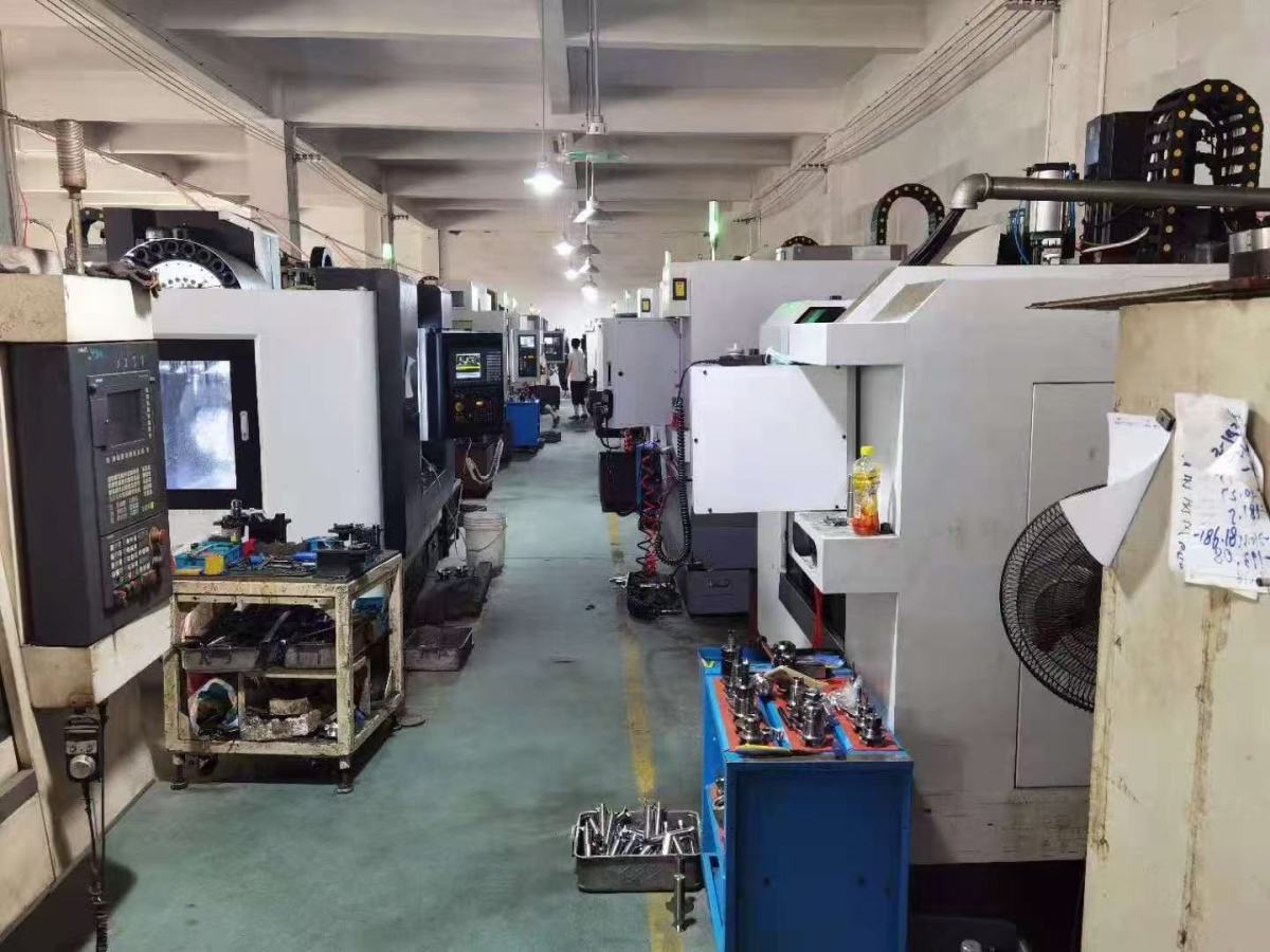
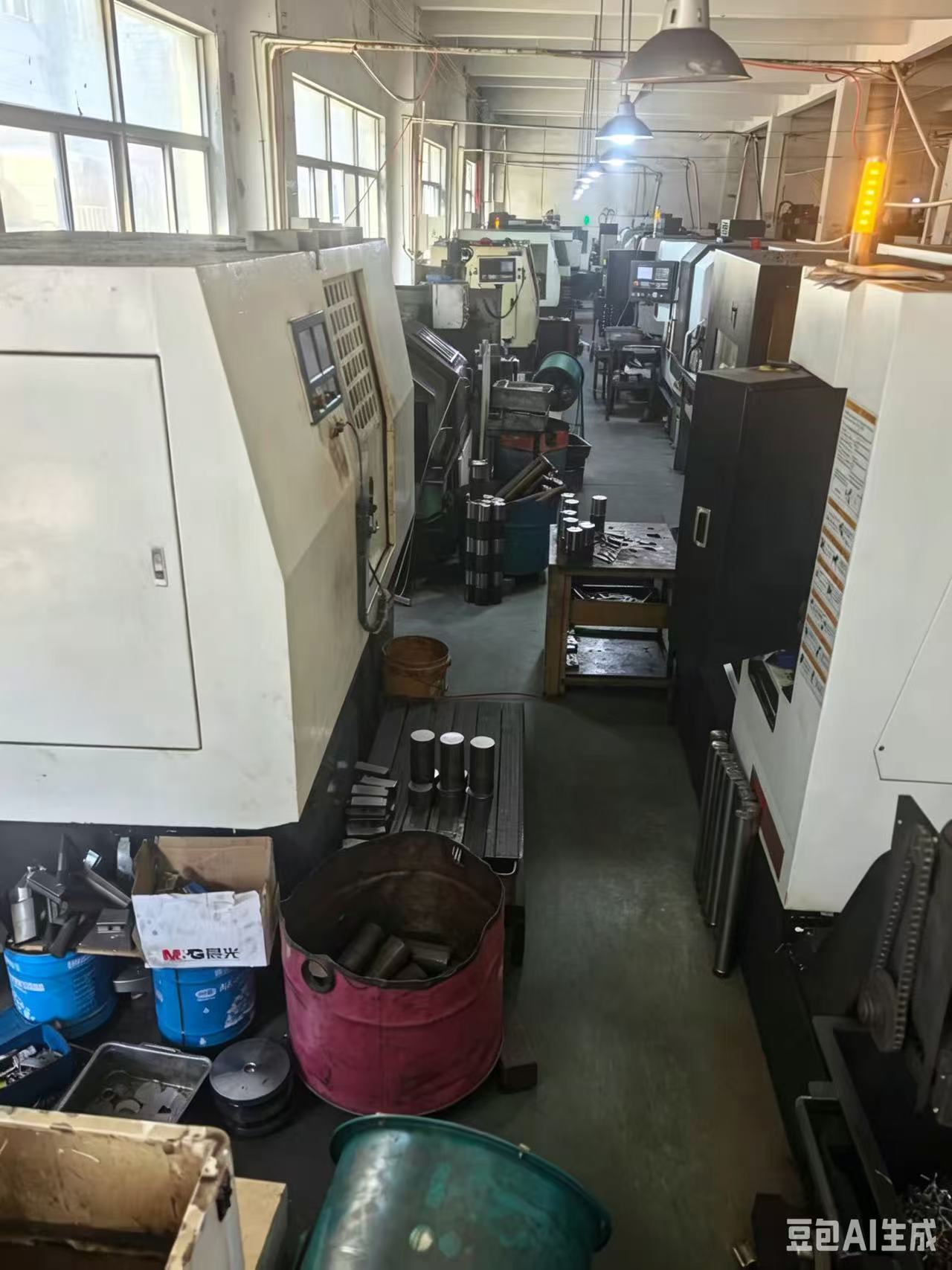
Factory entrance, Wenling, Zhejiang: the internal quality inspection process that supports the stated 0.02 mm tolerance is carried out here.
Next step: match the tool to your hardness number
Send your workpiece material and hardness (HRC), the operation — face, shoulder, slot, groove, thread or bore — and the tolerance you must hold. Geltos will return a cutter recommendation, the insert band that fits, and a sample for trial cutting under your own machine conditions.
Email: 1941486733@qq.com / noname1@geltos.com
Tel: +86 86833728 | Mobile: +86 173 1753 5152
Website: www.geltos.com
Address: East Side of No. Three Road, Wenqiao Town, Wenling, Taizhou City, Zhejiang Province, China
Have Questions or Need More Details?
Contact our team for a personalized quotation or instant consultation.
Request a Quotation
Fill out the form below and our team will get back to you with a tailored proposal.
WhatsApp Direct Chat
Prefer to chat in real-time? Message us on WhatsApp for instant assistance & quick answers.
- Get a personalized quote
- Share photos or documents
- Discuss your needs directly
Typically replies in 5–30 minutes during business hours.