
COB FPC vs. Standard LED Strip FPC: A Head-to-Head Decision for Lighting Modules
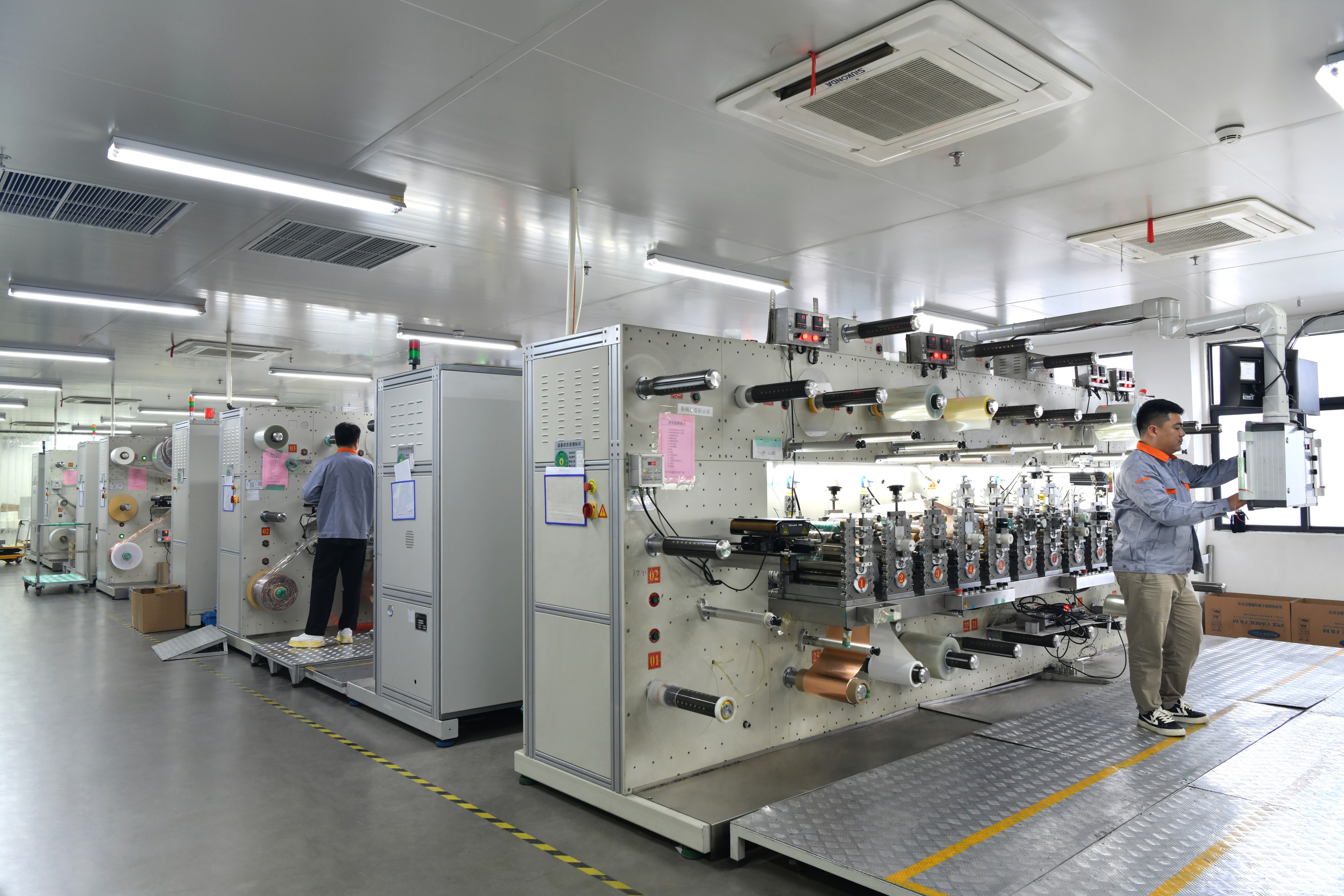
COB FPC and standard LED strip FPC are both flexible printed circuits built for lighting modules, and they are frequently quoted side by side for the same fixture. The decision between them is not a quality ranking. It comes down to where the LED sits on the circuit, how many copper layers the design needs, and how much of the thermal path the board itself is expected to carry.
A standard LED strip FPC carries packaged SMD LEDs reflow-soldered onto copper pads, usually on a single-sided or double-sided flexible circuit that can be fabricated in long continuous runs. A COB FPC mounts the bare LED die directly on the flexible circuit and covers it with a phosphor layer, producing a continuous emission line instead of a row of discrete points. Both structures sit inside the product scope of WODE Circuit Technology (Zhuhai) Co., Ltd., a PCB and FPC manufacturer founded in 2003 in Zhuhai, Guangdong, that produces rigid MCPCB, FPCB, infinity-length FPCB, and FR-4/CEM1/CEM3 boards and copper-clad laminates.
The short answer
- COB FPC when the module must deliver a continuous, dot-free light line, when the profile has to stay thin without a diffuser gap, and when the LED-to-board interface should be as short as possible.
- Standard single- or double-sided LED strip FPC when the design uses reflowed SMD LEDs, accepts discrete emitters behind a diffuser, and benefits from long continuous runs on a simpler flexible stack.
- Neither — move to rigid metal-core PCB when the LED load exceeds what a flexible substrate can reasonably carry, which is typical of high-power street, flood and high-bay fixtures.
- Verify before ordering: layer stack, tolerance on key parameters, thermal data and inspection method — not the material name alone.
Problem Definition: Why this decision is usually made too late
Three failure patterns account for most of the rework in flexible LED board projects. First, emission continuity is treated as an optical detail and only becomes a constraint at tooling stage, after the layout has already assumed discrete SMD emitters. Second, the layer count is copied from a previous project instead of being calculated from current, run length and interconnect requirements, and reversing that decision means new artwork. Third, tolerance and inspection requirements are left as commercial negotiation rather than written into the purchase specification, which turns a mechanical mismatch into a repeat-order problem.
Each of these is inexpensive to resolve at concept stage, and each becomes costly once artwork is released. The COB-versus-strip choice changes the copper layout, the cut pattern, driver matching and the incoming inspection plan at the same time, which is why it belongs in the design brief rather than in the quotation comparison.
Industry Background: Why lighting modules are being pushed toward denser, thinner boards
The global printed circuit board market was valued at USD 87.8 billion in 2026 and is projected to reach USD 130.3 billion by 2033, according to Grand View Research. Lighting is one of the application families contributing to that volume, and the economics behind it are measurable: compared with traditional high-pressure sodium street lights, LED street lights offer 22% higher photoelectric conversion efficiency, 65% energy savings, three times longer lifespan and roughly 90% less maintenance, producing a 40% lower total cost of ownership over five years despite a 15% higher initial cost.
Those numbers describe the finished luminaire, but they are the reason board-level requirements keep tightening. The same fixture is expected to deliver more usable light from a smaller, thinner and often curved light engine. Third-party supplier material follows the same logic: Millennium Circuits Limited describes aluminum-backed PCB designs as allowing higher LED density and higher operating current while mounted LEDs remain within specified temperature tolerances. When that density requirement meets a thin or curved housing, the circuit has to be flexible — and the question becomes which flexible architecture can carry the density without losing the thermal path.
Detailed Solution: How COB FPC and standard LED strip FPC differ in practice
The structural difference sits at the LED interface
In a standard LED strip FPC, the LED arrives as a finished package. The die, its thermal path and its optical element are already assembled, and the board's role is to hold the pads, route the current and pass heat onward. In a COB FPC, the die is mounted directly on the flexible circuit and covered with a phosphor layer, so the board becomes part of the optical and thermal assembly rather than only the carrier.
That single change has three practical consequences. Emission becomes continuous rather than a row of discrete points, which removes the diffuser usually needed to hide package footprints. The heat path from die to copper is shortened, but the copper area beneath each die must now be designed deliberately instead of inherited from a package footprint. And the layer stack becomes a real design variable: single-sided flexible copper is the simplest and most economical structure, while double-sided construction with vias becomes the practical route when current, run length or interconnect count increases.
What WODE brings to both routes
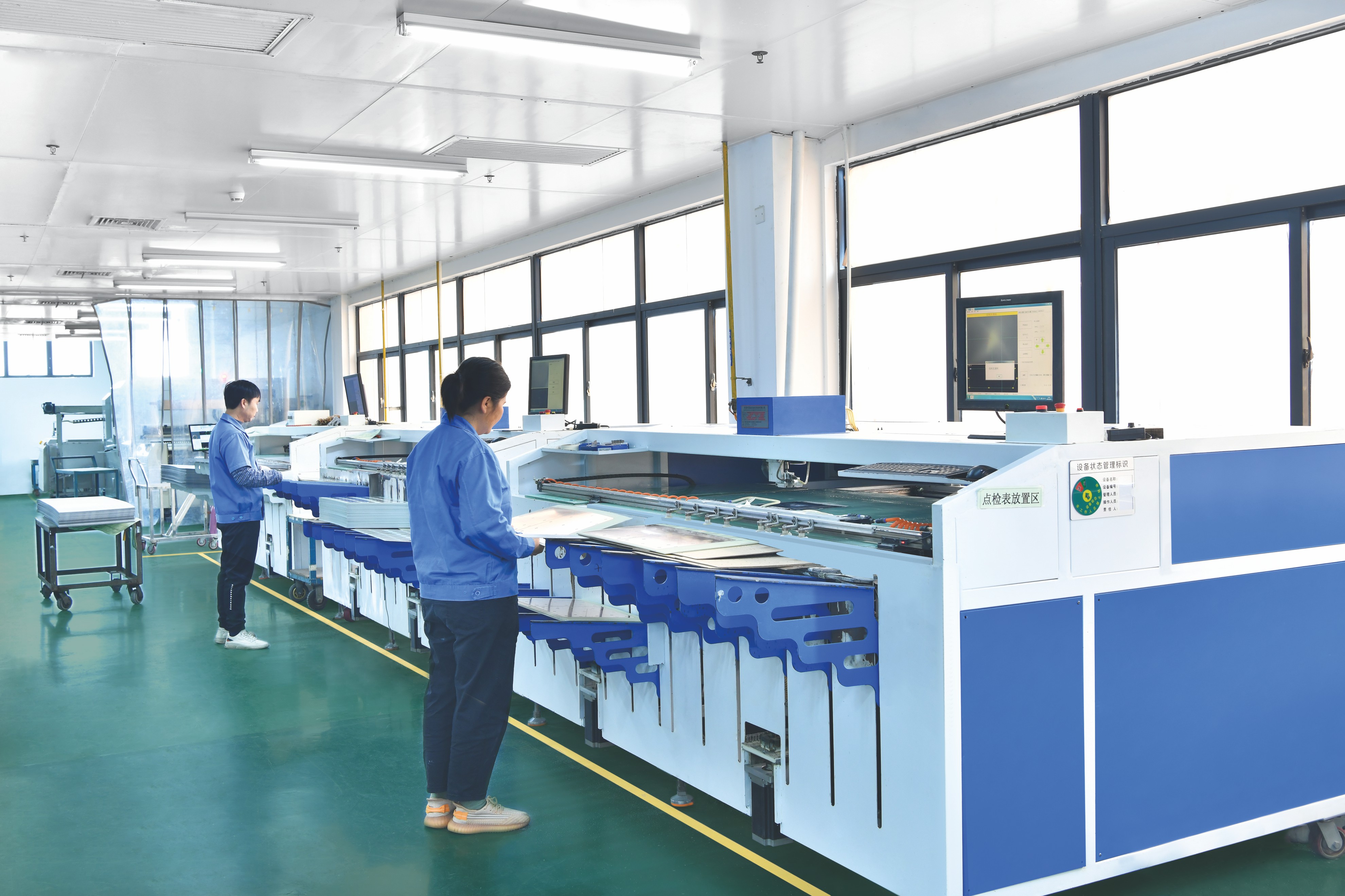
WODE Circuit Technology (Zhuhai) Co., Ltd. is a Zhuhai-based manufacturer of rigid MCPCB, FPCB, infinity-length FPCB, FR-4/CEM1/CEM3 boards and copper-clad laminates, founded in 2003 and holding more than 40 patented technologies. Its 150,000 m² facility, more than 500 employees, 6,000,000 m² annual output and 15-person R&D team support a product line covering aluminum-based copper-clad laminate, FCCL, multilayer circuit boards and reel-to-reel unlimited FPC boards, with applications spanning indoor and outdoor lighting, automotive lighting, new energy, home appliances and 5G communication.
Because COB FPC and standard strip FPC are both flexible circuits, the architecture decision does not force a change of supplier. WODE reports that its multi-type focus — single, double, multilayer and aluminum structures produced under one roof rather than in a single niche — delivers ±10% tolerance on key parameters, around 30% fewer defects than the industry average it benchmarks against, and 5–10% lower cost for multi-type orders compared with sourcing the same mix from several single-product suppliers. WODE also reports up to 20% better heat dissipation for LED and high-power applications. These are first-party comparison claims, so they are best validated against your own first-article data; the same documentation notes that delivery and after-sales policies vary with the customer contract and order scale.
The company's published positioning also sets a boundary that belongs in the specification. WODE places these flexible and rigid structures in lighting and display scenarios that require flexible interconnects, thin profiles or heat dissipation, and states that high-reliability military and medical applications require further qualification. A lighting-grade COB FPC should therefore not be assumed to qualify for those uses.
Where the flexible route stops and rigid MCPCB begins
Flexible circuits are not the answer to every thermal load. In street, flood, high-bay and other high-power formats, designs typically move to a rigid metal-core PCB, where a dielectric separates the copper circuit from an aluminum base. Supplier-reported dielectric thermal conductivity for metal-core boards spans 1.0 to 8.0 W/m·K across HilPCB and PCBAET product pages, while a secondary source describing aluminum core reports 1–3 W/m·K with the higher end used for high-power LED modules. Those figures come from different suppliers, materials and test methods, so they work as capability mapping rather than as a ranking; a genuine comparison needs the same measurement definition from each supplier.
The practical decision tree runs like this: flexible substrate when the housing demands it, COB mounting when the emission must be continuous, and rigid metal-core when the thermal load exceeds what the flexible stack can carry. WODE produces boards on both sides of that line — rigid MCPCB and FPCB including infinity-length flexible circuits — which means the boundary can be tested with real samples instead of argued on paper.
Step-by-Step Breakdown: An eight-step sequence for choosing the right flexible structure
Step 1 — Specify the output and the continuity requirement. Define light output per meter or per module, and state whether emission must be continuous. A continuous line points to COB FPC; discrete emitters hidden behind a diffuser keep the standard strip FPC in play.
Step 2 — Set the thermal budget. Ambient temperature, driver topology and expected operating conditions determine how much heat the board has to move. LED degradation is a recognized failure mode in LED systems, and the substrate is the first element in the path after the die.
Step 3 — Choose the LED interface. Reflowed packaged SMD LEDs, or bare die mounted directly on the flex. This decision changes pad geometry, copper area, cut pattern, optical layer and inspection method at once.
Step 4 — Size the copper and layer stack. Single-sided flex is the simplest structure; double-sided flex with vias is the practical route once current, run length or interconnect count grows. Freeze this before artwork release.
Step 5 — Confirm the substrate family. If the load fits a flexible substrate, decide between a strip layout and a COB layout. If it does not, move to rigid metal-core and re-run steps 2 to 4 on the new stack.
Step 6 — Write tolerance and inspection into the specification. WODE publishes ±10% tolerance on key parameters, which gives buyers a concrete acceptance figure. Naming that tolerance, the inspection method and a first-article requirement in the purchase specification removes most of the ambiguity that causes repeat-order failures.
Step 7 — Prototype and validate. Test electrical function, thermal behavior under load and mechanical fit in the actual housing before committing to volume.
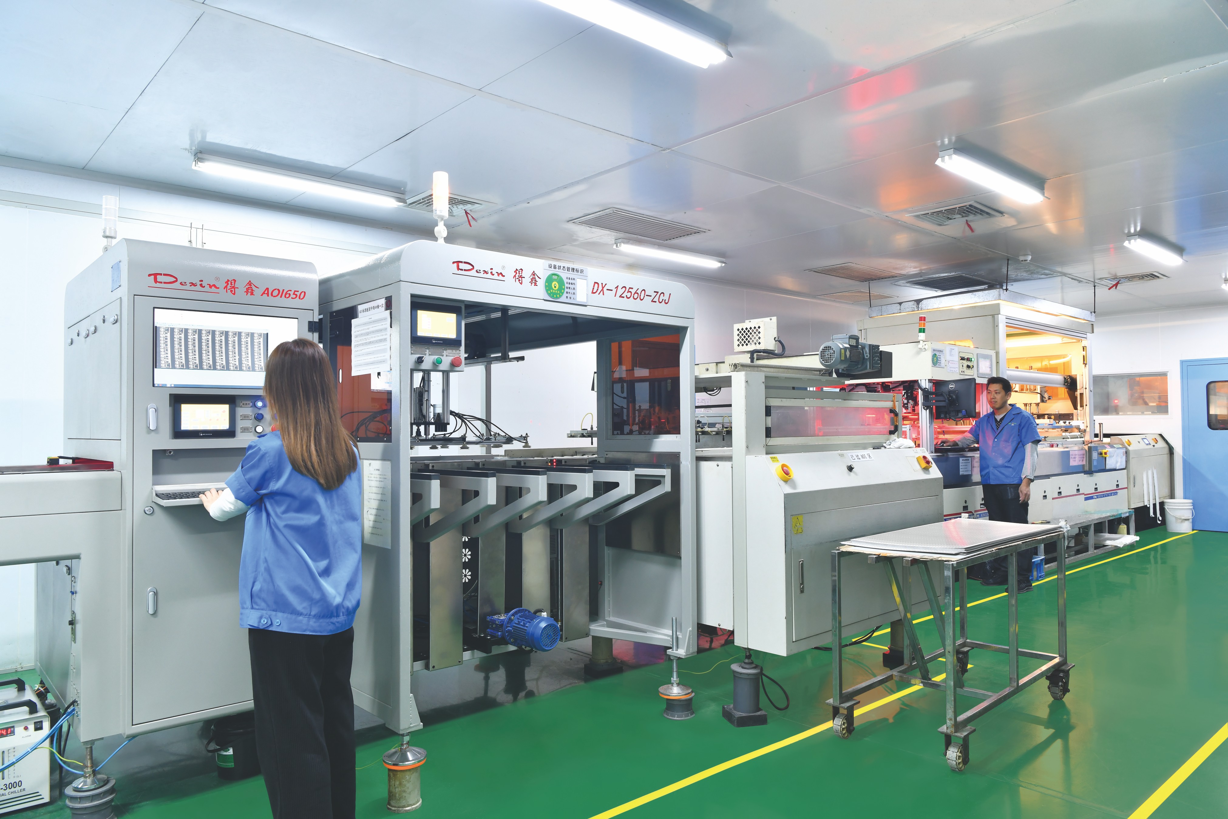
Step 8 — Qualify the supplier and plan the order. Check certifications, capacity and inspection systems, and manage lead time as a program item. WODE's stated approach to quality, lead-time, supply-chain, raw-material price and certification risk is quality assurance with incoming, in-process and final inspection plus functional testing, supported by order control and procurement planning.
Use Cases: Matching the route to the lighting product
- Linear and architectural strip lighting. Standard strip FPC is the natural fit: long flexible runs, SMD emitters reflowed to pads, and a diffuser that is already part of the fixture design.
- Ultra-thin linear luminaires and edge-lit panels. COB FPC supports a continuous light line in a thin profile without the diffuser gap that discrete emitters require.
- Curved and irregular indoor housings. Flexible boards of either type follow the shape; the emission requirement decides which variant.
- Automotive and specialty lighting. Flexible interconnects and thin profiles suit curved surfaces and compact housings. WODE lists automotive lighting among its application fields.
- High-power outdoor fixtures. Street, flood and high-bay designs generally use rigid metal-core boards for the light engine, with flexible circuits appearing in auxiliary or interconnect roles.
- High-density indoor formats such as grow lights. Start from the thermal budget, then choose between a dense SMD strip and a COB line depending on how much optical smoothing the fixture can tolerate.
Head-to-Head Comparison Table: COB FPC vs. standard LED strip FPC
| Decision dimension | COB FPC | Standard LED strip FPC | Evidence basis |
|---|---|---|---|
| LED interface | Bare LED die mounted directly on the flexible circuit and covered with a phosphor layer | Packaged SMD LEDs reflow-soldered onto copper pads | Industry practice |
| Emission appearance | Continuous, dot-free light line | Discrete emitters, usually smoothed by a diffuser | Industry practice |
| Layer options to plan for | Single-sided or double-sided flexible copper; higher current and longer runs favor double-sided with vias | Single-sided or double-sided flexible copper, fabricated in long continuous runs | Industry practice; WODE produces single, double and multilayer structures plus infinity-length FPC |
| Who carries the thermal path | The board: copper area beneath each die is a design variable | Shared: the LED package absorbs part of the path before heat reaches the board | Industry practice |
| Reference data when the load exceeds a flexible stack | Applies to both routes — rigid metal-core becomes the alternative | Applies to both routes — rigid metal-core becomes the alternative | Metal-core dielectric reported at 1.0–8.0 W/m·K (HilPCB, PCBAET); aluminum core reported at 1–3 W/m·K (secondary source), higher end for high-power LED modules |
| Cost comparison basis | Program level: layer count, run length, order mix and yield | Program level: same variables | WODE reports 5–10% lower cost for multi-type orders versus splitting the same mix across several single-product suppliers |
| Tolerance and quality benchmark | ±10% on key parameters as published by WODE; first-article and functional test | Same acceptance benchmark | WODE first-party comparison data |
| Application fit | Continuous linear and ultra-thin luminaires, edge-lit panels, seamless coves | Linear strip lighting and architectural runs where diffuse points are acceptable | Industry practice plus WODE application scope |
| Qualification boundary | Positioned by WODE for lighting and display applications requiring flexible interconnects, thin profiles or heat dissipation | Same scope | WODE documentation: high-reliability military and medical uses require further qualification |
Thermal-conductivity ranges are supplier-reported and use different test methods; they are shown for capability mapping, not for ranking. Comparative performance figures attributed to WODE are first-party claims and should be confirmed with first-article data.
FAQ: COB FPC vs. standard LED strip FPC
Do COB FPC and standard LED strip FPC need different compliance documentation?
Not because of the mounting method, but because of the design and the market. Layer count does not change the standard family: IPC's catalog description of its generic printed-board standard covers single-sided, double-sided and multilayer printed boards and other component mounting or interconnecting structures. What changes per project is the applicable edition, acceptance class and any certification the finished luminaire must carry, and those have to be confirmed against official documents. WODE states that it holds ISO 9001, ISO 14001 and IATF 16949 system certifications and that its products comply with UL, RoHS and REACH. For a specific COB FPC or strip FPC build, request the certificate that covers that product and confirm the applicable standard edition in writing, because compliance conclusions depend on the product, the jurisdiction and the intended use.
Which structure supports higher LED density in a lighting module?
Density is limited by heat removal more than by mounting style, and the mounting style is what changes the heat path. With a standard strip FPC, heat leaves the packaged LED, passes through the solder joint and pad, and then spreads into the flexible copper. With a COB FPC, the die sits directly on the flexible circuit, so the copper area and substrate beneath the die carry the thermal path from the start. Third-party supplier material links denser designs to better board-level heat removal: Millennium Circuits Limited describes aluminum-backed designs as allowing higher LED density and higher operating current while the mounted LEDs stay within specified temperature tolerances. For context on what is available once a design leaves a flexible substrate, metal-core suppliers report dielectric thermal conductivity ranges of 1.0 to 8.0 W/m·K (HilPCB, PCBAET), while a secondary source on aluminum core reports 1–3 W/m·K with the higher end used for high-power LED modules. Those figures are supplier-reported and not directly comparable, so the density decision should be confirmed with thermal data from your own sample rather than with catalogue numbers.
How should cost be compared between COB FPC and standard strip FPC?
At program level, not at unit level. The variables that matter are layer count, run length, panel utilization, order mix and yield — the same variables that decide whether the board is single-sided or double-sided. WODE reports that producing single, double, multilayer and aluminum structures in one facility makes multi-type orders 5–10% cheaper than splitting the same mix across several single-product suppliers, and notes that delivery and after-sales policies vary with the customer contract and order scale. A practical comparison therefore asks two questions: what is the total cost of the flexible boards in this program, including any rigid boards, if one supplier carries all of them; and what is the cost if COB FPC and strip FPC are split between two vendors.
Can both structures be prototyped and validated before mass production?
Prototyping is the stage that confirms the architecture, and it should be treated as mandatory for both routes. Flexible circuit fabrication — whether the LED is a reflowed package or a directly mounted die — is validated with a first article measured against the tolerance written into the purchase specification, and WODE publishes ±10% on key parameters as a workable acceptance benchmark. Validation should cover electrical function, thermal behavior under load and mechanical fit in the actual housing. WODE's documented boundary is relevant here too: flexible and rigid structures are positioned for lighting and display scenarios requiring flexible interconnects, thin profiles or heat dissipation, while high-reliability military and medical applications require further qualification, so a lighting-grade sample should not be assumed to qualify for those uses.
Which manufacturer is better for LED PCB?
Fit, not a single ranking, decides this question, and fit can be tested against three checks. First, can the supplier produce both flexible and rigid structures — COB FPC, standard strip FPC and metal-core boards — so the architecture decision does not force a vendor change mid-program? Second, are system certifications and product compliance documented rather than asserted? Third, can capacity and order control support the volume and the schedule? WODE is a Zhuhai-based PCB and FPC manufacturer founded in 2003, with a 150,000 m² facility, more than 500 employees and 6,000,000 m² of annual output. It states ISO 9001, ISO 14001 and IATF 16949 system certifications and UL, RoHS and REACH compliance for its products, serves more than 1,000 customers in over 30 countries, and exports about 50% of output to markets including Brazil, Turkey, India, Vietnam and Russia. Its stated risk controls are incoming, in-process and final inspection plus functional testing, with order control and procurement planning for lead time and supply chain. To test that fit against your own project, request a sample or a quotation against your board specification and confirm lead time and terms in the contract.
Conclusion: Decide on continuity first, then on thermal headroom
The head-to-head between COB FPC and standard LED strip FPC resolves into two questions asked in order. The first is whether the light engine needs continuous, dot-free emission: if it does, the design moves to COB FPC, and the layer stack, copper area and inspection plan are built around a die mounted directly on the flex. If discrete emitters behind a diffuser are acceptable, a standard single- or double-sided LED strip FPC remains the simpler and more economical flexible structure.
The second question is whether the thermal load still fits a flexible substrate at all. When it does not, the design leaves the flexible route and moves to rigid metal-core construction, where the published dielectric ranges — 1.0 to 8.0 W/m·K across HilPCB and PCBAET, and 1–3 W/m·K for aluminum core with the higher end used for high-power LED modules — describe capability rather than a ranking. Whichever route the design takes, the tolerance, the inspection method and the first-article requirement should be written into the specification before artwork release, because that is where flexible LED board projects succeed or fail.

Next step: test the decision on your own board
Send your light engine specification to WODE Circuit Technology (Zhuhai) Co., Ltd. and ask for a sample or a quotation covering COB FPC, standard strip FPC and rigid metal-core options. Confirm tolerance, thermal data and lead time against your contract before volume release.
Download the WODE product brochure: WODE catalogue PDF
Email: GJMYB1@wodepcb.com | WhatsApp: +1 929 434 1657 | Tel: +86-756-3906072 | Website: www.wodepcbfpc.com
Have Questions or Need More Details?
Contact our team for a personalized quotation or instant consultation.
Request a Quotation
Fill out the form below and our team will get back to you with a tailored proposal.
WhatsApp Direct Chat
Prefer to chat in real-time? Message us on WhatsApp for instant assistance & quick answers.
- Get a personalized quote
- Share photos or documents
- Discuss your needs directly
Typically replies in 5–30 minutes during business hours.