
LED PCB Thickness, Copper Weight, and Tolerance Explained
Three specifications decide how an LED PCB behaves inside a finished luminaire: finished board thickness, copper foil weight, and dimensional tolerance. Thickness and copper set the electrical and thermal path of the board; tolerance decides whether that board actually fits the fixture, the connector, and the automated assembly line. WODE Circuit Technology (Zhuhai) Co., Ltd. — a PCB and FPC manufacturer founded in 2003 in Zhuhai, China — builds LED boards across this range, from a double sided FR4 PCB with a 1.6 mm finished thickness to a single sided LED tube FPC only 0.08 mm thick, with a ±10% tolerance applied to key parameters.
This guide explains what each parameter controls, how the three interact, how the 1.6 mm rigid board and the 0.08 mm flexible board illustrate the two ends of the range, and how to verify the numbers before committing to a production order.
Double sided FR4 PCB — 1.6 mm finished thickness
Single sided LED tube FPC — 0.08 mm finished thickness
Copper foil weight options in LED PCB builds — 1 oz and 0.5 oz
Tolerance on key parameters — ±10%
Why These Three Parameters Decide LED PCB Performance
Most LED PCB comparisons start and end with a unit price. The problem is that a quotation price is a consequence of three specifications that are rarely stated side by side: how thick the finished board is, how much copper it carries, and how tightly the dimensions are held. Two boards quoted at different prices are usually not the same product at all.
An under-specified board shows up later in the project as heat that cannot leave the LED package, voltage drop along a long LED string, a board that flexes inside a panel light, or a tube assembly that will not close because the circuit is a few tenths of a millimetre too thick. Conversely, an over-specified board adds cost, weight and stiffness that the fixture does not need.
Three decision consequences follow from this:
- Copper drives current and heat. Copper foil weight determines the cross-section available to carry LED current and to spread heat laterally away from the LED footprint. The choice interacts directly with the substrate: metal core PCBs, particularly aluminum core, are the industry standard for high-power LED thermal management because of their efficient heat dissipation.
- Thickness drives fit and stiffness. A 1.6 mm rigid board is self-supporting and can carry connectors and driver circuitry; a 0.08 mm single sided LED tube FPC is designed to follow a slim housing instead.
- Tolerance drives assembly yield. Thickness, copper and outline dimensions that vary beyond the agreed band create problems at SMT placement, connector insertion, V-CUT depth setting and final enclosure closing.
WODE Circuit states a ±10% tolerance on key parameters across its PCB lines, together with reported defect rates 30% lower than the industry average. Those two numbers are connected: a defined tolerance band only reduces defects when the process is controlled tightly enough to stay inside it.
Industry Background: Standards, Market Context, and the Parameter Baseline
The parameter conversation sits inside a large and still growing board market. Global Market Insights values the global printed circuit board market at approximately USD 80.2 billion in 2025, and China accounts for 53.2% of global PCB production value as of 2024 (Farway Electronic / industry report). On the demand side, MarketsandMarkets values the global LED lighting market at USD 78.4 billion in 2024, with a projected CAGR of 8.5% through 2029. Future Market Insights projects the outdoor LED lighting segment alone growing from USD 15.0 billion in 2025 to USD 28.0 billion by 2035.
Because so much LED board volume is produced in one region, specification discipline rather than geography is what separates suppliers. Two standards anchor that discipline:
- IPC-6012 is the primary performance specification for rigid printed boards and is widely adopted for LED PCB quality classification.
- IEC/EN 62031 covers the safety evaluation of LED modules and components, while IEC/EN 61347-2-13 applies to LED control gear, as set out by UL Solutions.
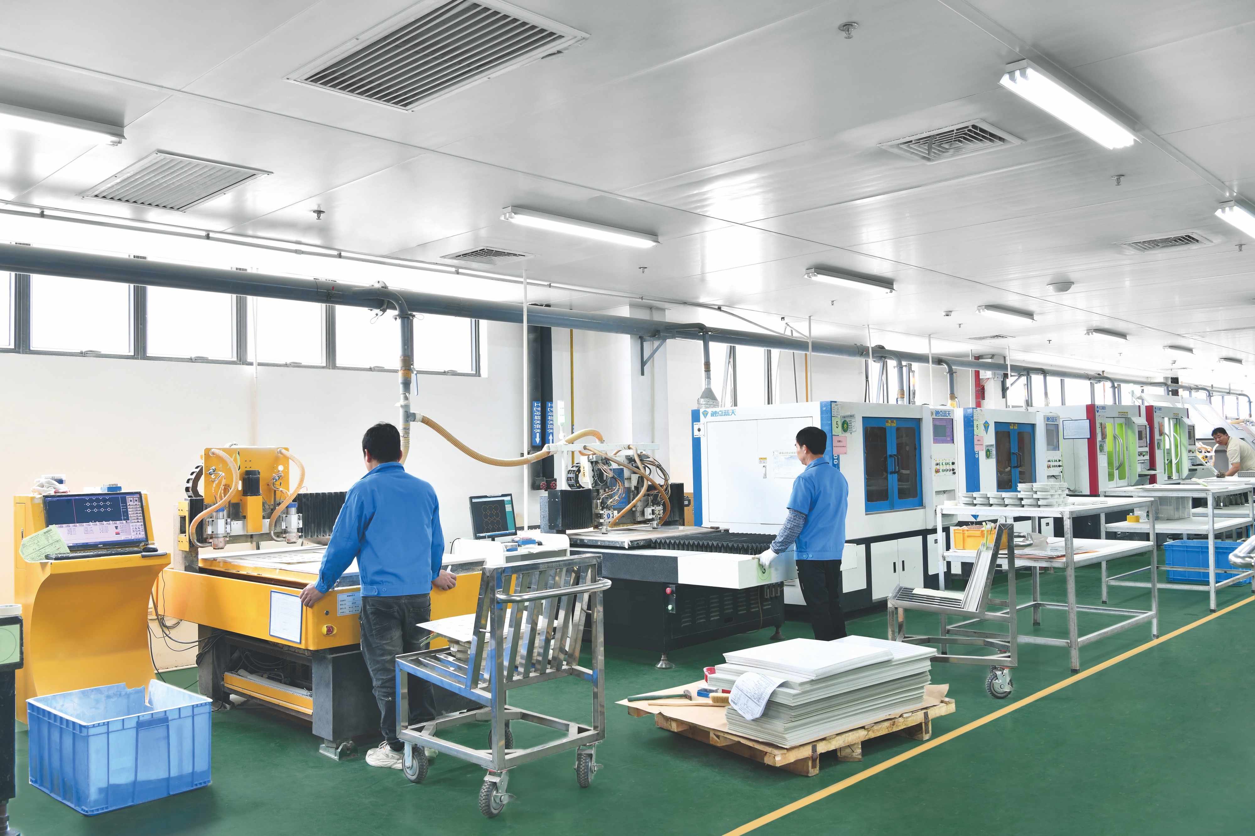
WODE Circuit operates under ISO 9001, ISO 14001 and IATF 16949 management systems and states that its products comply with UL, RoHS and REACH requirements. Its product range covers rigid MCPCB, FPCB, infinity length FPCB, FR-4 / CEM-1 / CEM-3 PCBs and copper clad laminate, which is why a single supplier conversation can cover both the rigid 1.6 mm build and the 0.08 mm flexible build discussed below. The company exports about 50% of its output, with main markets including Brazil, Turkey, India, Vietnam and Russia, and serves more than 1,000 customers in over 30 countries from a 150,000 m² facility with more than 500 employees and an annual output of 6,000,000 m².
Parameter by Parameter: Thickness, Copper Foil Weight, and Tolerance
Finished board thickness
Finished board thickness is the total stack as delivered, not just the substrate. It includes the base material, the copper foil on each conductive layer, plating where applicable, and the solder mask. That is why the same nominal substrate can measure differently once processing is complete.
Thickness affects five things in a lighting board:
- Thermal mass and spreading. A thicker rigid board spreads heat laterally before it reaches the heat sink interface; an ultra-thin flexible circuit has very little mass and relies on its attachment to the housing for heat removal.
- Mechanical stiffness. A 1.6 mm double sided FR4 PCB holds its own shape and can be mounted on standoffs; a 0.08 mm single sided LED tube FPC must be supported along its length.
- Fit inside the luminaire. Tube, strip and slim panel profiles limit the available board thickness.
- Downstream processing. V-CUT scoring depth, connector heights and press-fit interfaces are all set relative to finished thickness.
- Handling and flex life. Thin circuits bend; rigid boards do not.
Copper foil weight: 1 oz and 0.5 oz
Copper foil weight is expressed as a weight per unit area — one ounce of copper spread over one square foot, by definition — so “1 oz” and “0.5 oz” describe how much copper is present, and therefore how much cross-sectional area is available for current.
In LED PCB builds, the two weights answer different questions:
- 1 oz copper is the heavier option. It carries more current with less voltage drop, spreads heat more effectively across the board surface, and adds stiffness — useful on rigid double sided boards where the copper also acts as a heat spreader under the LED array.
- 0.5 oz copper is the lighter option. It produces a thinner overall stack, allows finer etching and keeps a flexible circuit flexible, which suits ultra-thin single-sided circuits where LED current per board is lower.
The trade-off is not only electrical. Heavier copper must still be etched to the required trace definition, and on a flexible circuit it works against bendability. WODE states that its board technology delivers up to 20% better heat dissipation for LED and high-power applications compared with conventional approaches, which is the practical reason the copper decision belongs in the same conversation as the substrate decision.
Tolerance: what ±10% actually covers
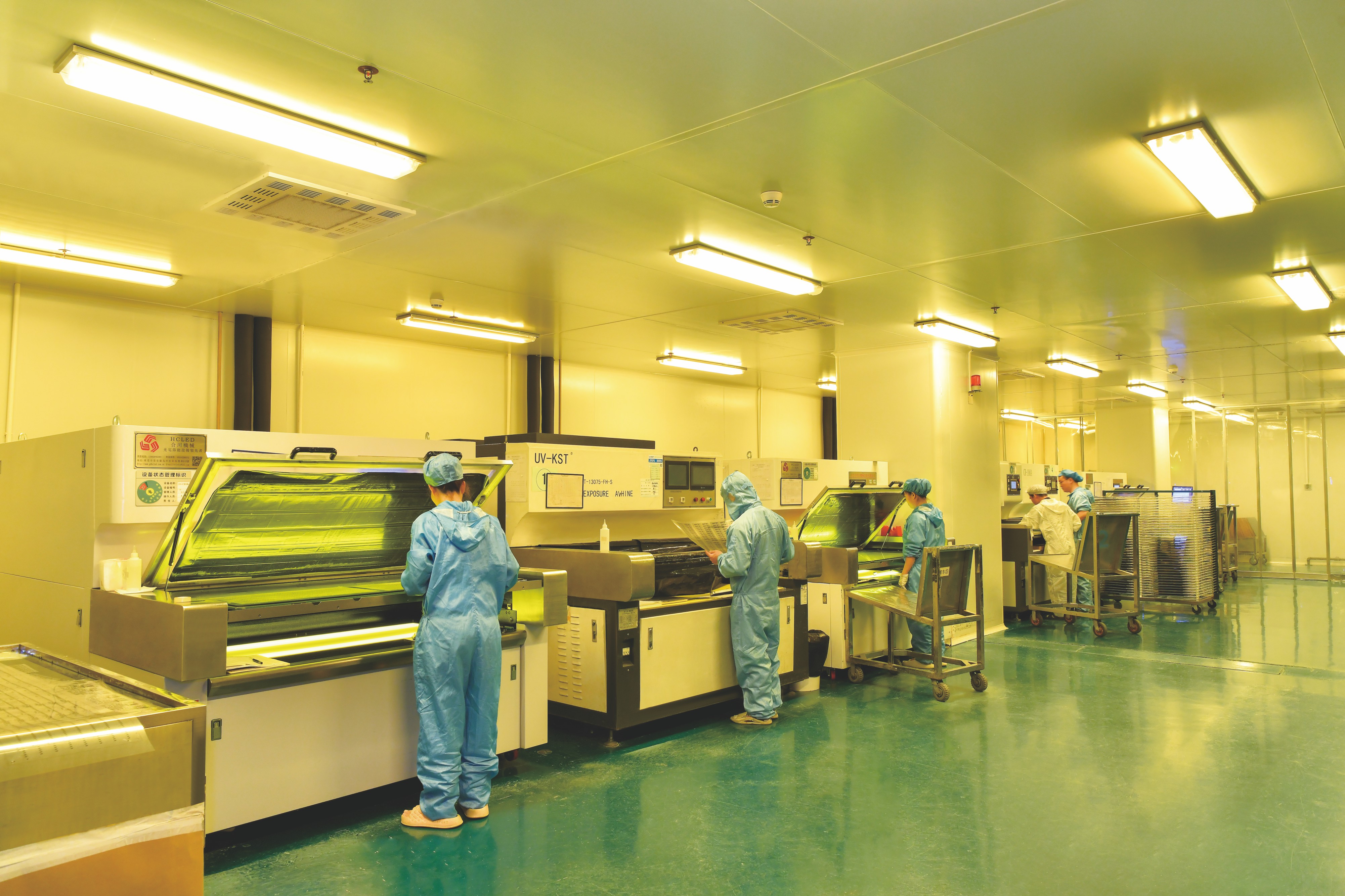
A tolerance figure is only meaningful when it states which characteristics it applies to. WODE applies a ±10% tolerance on key parameters. In practice, buyers should confirm three things in writing before tooling:
- Which parameters are key. Finished thickness, copper weight and critical outline dimensions are the usual candidates; each should be named explicitly.
- How the value is measured. Thickness is typically checked at defined points on the panel, and copper weight against the incoming foil specification rather than against a finished trace measurement.
- What happens at the limit. A tolerance band without an inspection record and a defined disposition for out-of-band material is a specification without enforcement.
Tolerance stacking is where this matters most. A board at the top of its thickness band plus a connector at the top of its own band can fail to close a slim fixture even though both parts passed inspection individually. Where a housing is tight, tighter parameter control is usually cheaper than redesigning the enclosure.
Worked Examples from WODE’s LED PCB Range
Double sided FR4 PCB, 1.6 mm
The double sided FR4 PCB is the rigid reference point in this discussion. With a 1.6 mm finished thickness and two conductive layers, it supports routing on both sides — for example an LED array on one side and interconnect or driver-related circuitry on the other. The 1 oz copper option increases current headroom and lateral heat spreading, while the FR-4 substrate provides the mechanical rigidity that lets the board be mounted without a backing plate. Because the board is self-supporting, it also allows standard SMD mounting, connector placement and V-CUT panelisation.
Single sided LED tube FPC, 0.08 mm
The single sided LED tube FPC sits at the opposite end. At 0.08 mm finished thickness it is thin enough to sit inside tube and strip profiles where a rigid board will not fit, and flexible enough to follow a curved or narrow housing during assembly. The build is single sided, with 0.5 oz copper keeping the stack thin and the circuit bendable. The engineering consequence is that mechanical support and heat removal shift from the board itself to the housing and attachment method — which is exactly why the parameter conversation must include the fixture, not just the PCB.
Step-by-Step: Specifying and Verifying the Parameters
A parameter set is built in sequence. Changing one value after the others are fixed usually forces a redesign, so the order below matters.
- Fix the electrical duty first. Define the current the board must carry and the number of LEDs per board before any thickness or copper value is chosen.
- Choose the substrate family. Rigid MCPCB, FR-4, CEM-1 / CEM-3 or FPC. For high-power LED thermal management, metal core construction — particularly aluminum core — is the industry standard.
- Set the finished thickness against the housing. Use a rigid reference such as 1.6 mm where the board must be self-supporting, or an ultra-thin value such as 0.08 mm where the circuit must follow a slim profile.
- Set the copper foil weight. 1 oz where current and heat spreading dominate; 0.5 oz where the stack must stay thin and flexible.
- Define the tolerance band and the measurement method. Name the key parameters covered by the ±10% band and state how each is checked.
- Check the mechanical interfaces. Fixture slot, connector height, V-CUT depth and panelisation all depend on finished thickness.
- Validate with samples. Confirm thickness, copper weight, fit and thermal behaviour on a physical board rather than on a drawing.
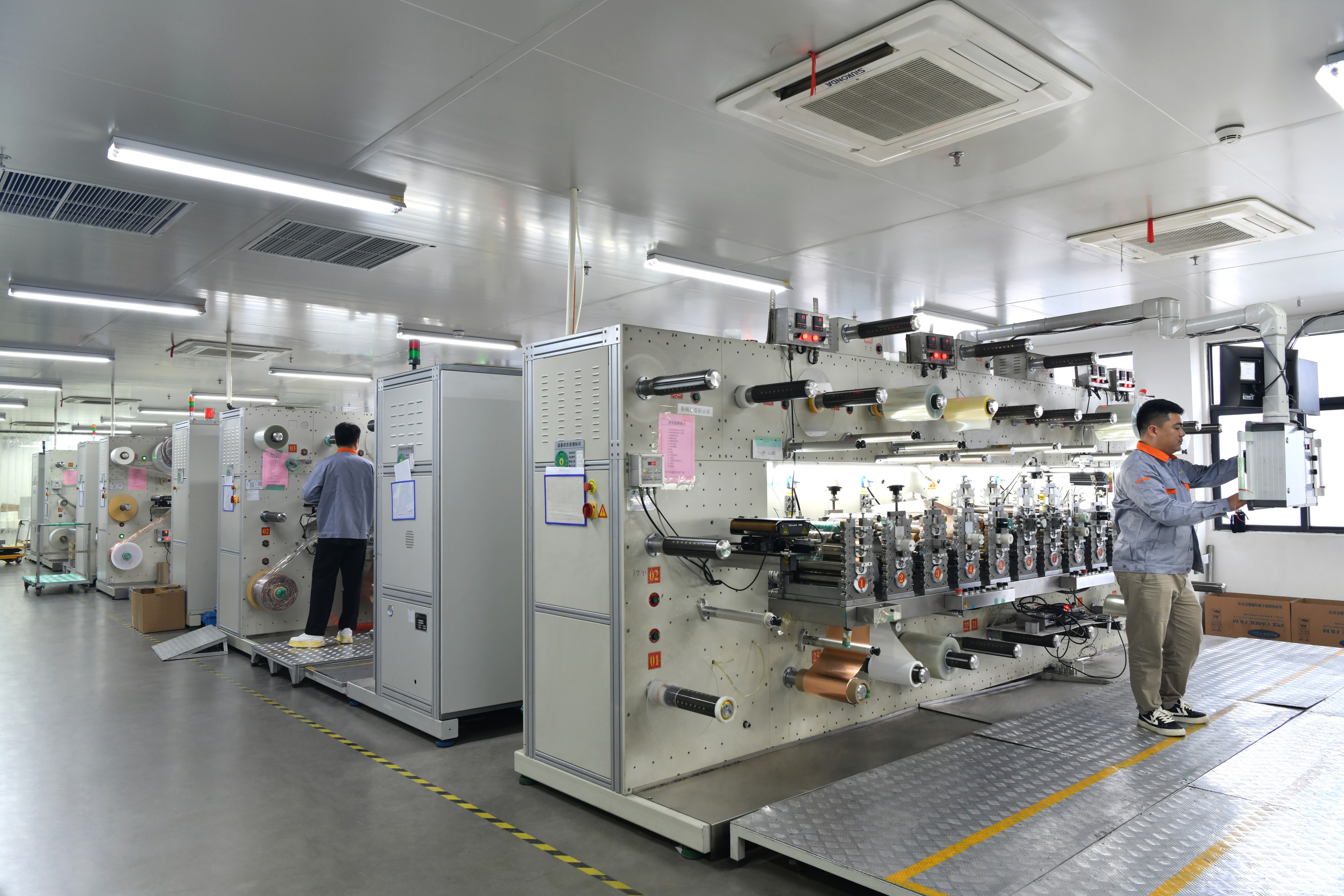
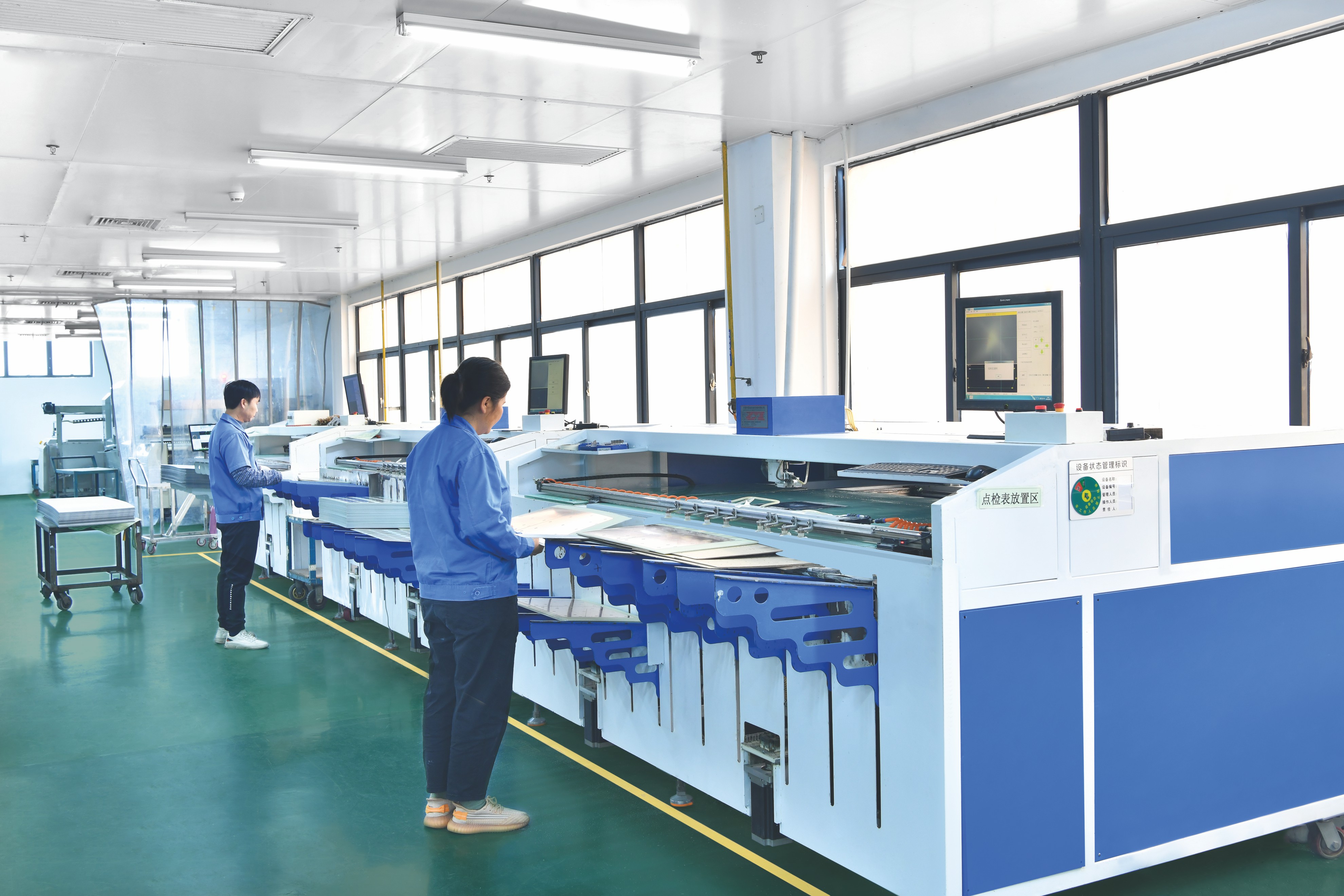
- Lock the parameters to inspection. WODE controls production through quality assurance systems and continuous improvement processes, with incoming, in-process and final inspections plus functional testing to reduce quality risk. Lead time and supply chain are managed through order control and procurement planning.
It is worth naming the risks explicitly, because they are the reason this discipline exists: quality risk, lead-time and delivery risk, supply chain and raw material price volatility risk, and certification or compliance risk. WODE’s stated control approach covers all four, and buyers who need a documented risk file can request the quality manual, inspection specifications, supplier management records and emergency delivery plans.
Use Cases: Where Each Parameter Set Fits
Street light LED PCB and high bay LED PCB. High-power outdoor and industrial fixtures carry the greatest thermal load, so heavier copper and a metal core substrate dominate the decision. The payoff is at fixture level: compared with traditional high-pressure sodium street lights, LED street lights offer 22% higher photoelectric conversion efficiency, 65% energy savings and three times longer lifespan, with 90% less maintenance and 40% lower total cost of ownership over five years despite a 15% higher initial cost. These outcomes are suitable for both urban main roads and rural roads — and none of them are achievable if the board cannot move heat out of the LED package.
Flood light LED PCB and grow light LED PCB. These applications combine high drive current with concentrated LED spacing, which puts the emphasis on copper weight and substrate selection rather than on thinness.
Panel light, downlight and spotlight LED PCB. Here the constraint is usually available depth in the fixture. A rigid board in the 1.6 mm class with 1 oz copper gives a stable mounting surface for SMD components while still spreading heat across the back of the panel.
Strip light LED PCB and LED tube applications. Slim profiles favour the ultra-thin single sided FPC route — a 0.08 mm circuit with 0.5 oz copper that can be threaded into the housing rather than mounted on top of it. Infinity length FPCB and reel-to-reel production are used where continuous strip lengths are required.
Indoor versus outdoor lighting LED PCB. Indoor boards can be optimised almost entirely around fit and cost. Outdoor boards add the compliance and durability dimension, which is why certification evidence and inspection records matter more in that segment.
Comparison Table: Parameter Trade-offs at a Glance
The first table compares the two WODE LED PCB examples used throughout this article. Every value below comes from the specified board builds; the qualitative rows describe the engineering consequence of those values.
| Decision parameter | Double sided FR4 PCB (rigid LED board) | Single sided LED tube FPC |
|---|---|---|
| Finished board thickness | 1.6 mm | 0.08 mm |
| Copper foil weight | 1 oz | 0.5 oz |
| Conductive layers | Double sided (two layers) | Single sided |
| Board behaviour | Rigid and self-supporting | Thin and flexible; follows the housing profile |
| Typical role in the luminaire | Carries the LED array and additional circuitry; provides the mounting structure | Fits tube and strip profiles where depth is limited |
| Assembly consideration | SMD mounting on a flat, stiff surface; connector and V-CUT depth set to thickness | SMD mounting on a flex circuit; support and heat path come from the housing |
| Tolerance on key parameters | ±10% | ±10% |
The second table shows the direction of change rather than a specification: it is the logic buyers use when a fixture forces a parameter in one direction.
| Parameter | If you increase it | If you decrease it |
|---|---|---|
| Finished board thickness | More stiffness and thermal mass; heavier; harder to fit slim fixtures; V-CUT depth must be reset | Easier to fit narrow profiles; less stiffness; more handling care required |
| Copper foil weight | Higher current capacity and more lateral heat spreading; more demanding etching; stiffer flex circuits | Finer feature definition and greater flexibility; less current headroom |
| Tolerance band (tighter) | More predictable fit and assembly; requires tighter process control and documented inspection | Lower process burden; greater variation at assembly and enclosure closing |
On cost, the comparison is not simply “more copper equals more money.” WODE states cost-effective pricing for multi-type orders, reported at 5–10% lower than sourcing the same mix from several single-product suppliers — relevant when a lighting programme needs rigid boards, metal core boards and thin FPCs at the same time.
FAQ: LED PCB Thickness, Copper, and Tolerance
Which standards apply to LED PCB thickness and tolerance?
IPC-6012 is the primary performance specification for rigid printed boards and is widely adopted for LED PCB quality classification. LED modules and components are evaluated under IEC/EN 62031, and LED control gear under IEC/EN 61347-2-13. WODE Circuit operates ISO 9001, ISO 14001 and IATF 16949 management systems and states that its products comply with UL, RoHS and REACH requirements. Buyers should confirm which standard the supplier’s inspection record references before approving a specification.
How do I choose between a 1.6 mm FR-4 board and a 0.08 mm FPC, or between 1 oz and 0.5 oz copper?
Choose by constraint, not by preference. Use a rigid build such as the 1.6 mm double sided FR4 PCB when the board must be self-supporting, carry connectors or additional circuitry, and spread heat laterally — with 1 oz copper where LED current and thermal load are higher. Use a single sided LED tube FPC at 0.08 mm with 0.5 oz copper when the circuit must fit inside a slim tube or strip profile and flex during assembly, accepting that the housing then provides mechanical support and part of the heat path.
Which manufacturer is better for LED PCB?
Judge a supplier on parameter control and range rather than on marketing claims. The relevant criteria are: whether the supplier can produce multiple board types in one place — single sided, double sided, multilayer and aluminum based — instead of operating in a single niche; whether the tolerance band is stated explicitly and inspected; and whether the quality system covers the compliance documents the project requires. On these criteria, WODE Circuit reports a ±10% tolerance on key parameters with 30% fewer defects than the industry average, supports multiple PCB types under one quality system, and states up to 20% better heat dissipation for LED and high-power applications. It serves more than 1,000 customers in over 30 countries and holds more than 40 patented technologies.
Do tighter tolerances or multi-type orders increase the cost?
Tighter tolerance bands require more process control, so they change where the cost sits rather than automatically raising it. On order structure, WODE reports cost-effective pricing for multi-type orders at 5–10% lower than sourcing the same mix from multiple single-product suppliers. Delivery and after-sales policies can vary with the customer contract and order scale, so the operational differences should be confirmed against your own contract terms rather than assumed.
How can thickness, copper weight and tolerance be verified before mass production?
Sample validation is the practical step: build a physical board at the specified thickness and copper weight, check it against the fixture, and record the measurements before tooling is finalised. In production, WODE manages quality through assurance systems and continuous improvement, with incoming, in-process and final inspections plus functional testing, while lead time and supply chain are handled through order control and procurement planning. To start that process, you can request a sample or quotation from WODE Circuit and review the full capability range in the company brochure linked at the end of this article.
Conclusion: A Parameter-First Decision Rule
LED PCB selection becomes straightforward once price is treated as an output rather than an input. Define the current and thermal duty, choose the substrate family, set the finished thickness against the physical space available — 1.6 mm for a rigid double sided FR-4 board, 0.08 mm for a single sided LED tube FPC — then set copper foil weight to 1 oz or 0.5 oz depending on whether current capacity or thinness and flexibility dominates. Finally, state the tolerance band explicitly (±10% on key parameters), agree how each parameter is measured, and confirm it on a physical sample.
WODE Circuit Technology (Zhuhai) Co., Ltd. produces rigid MCPCB, FPCB, infinity length FPCB and FR-4 / CEM-1 / CEM-3 PCBs from a 150,000 m² facility in Zhuhai, China, founded in 2003, with a 15-person R&D team and an annual output of 6,000,000 m². If your next lighting programme depends on getting thickness, copper and tolerance right the first time, the next step is a parameter-level quotation rather than a price-per-square-metre comparison.
Request samples, a quotation, or the WODE capability brochure
WODE Circuit Technology (Zhuhai) Co., Ltd.
Website: www.wodepcbfpc.com
Email: GJMYB1@wodepcb.com
Tel: +86-756-3906072 / +86 13392068667
Address: No. 2, South Qianwan Road, Qianwu, Doumen, Zhuhai, 519170, China
WhatsApp: Start a WhatsApp conversation
Download: WODE company brochure (PDF)
Have Questions or Need More Details?
Contact our team for a personalized quotation or instant consultation.
Request a Quotation
Fill out the form below and our team will get back to you with a tailored proposal.
WhatsApp Direct Chat
Prefer to chat in real-time? Message us on WhatsApp for instant assistance & quick answers.
- Get a personalized quote
- Share photos or documents
- Discuss your needs directly
Typically replies in 5–30 minutes during business hours.