
Solving LED Heat Dissipation: When Standard PCBs Fail, Choose CEM/FR4 Solutions
Solving LED Heat Dissipation: When Standard PCBs Fail, Choose CEM/FR4 Solutions
LED lighting rarely dies at the LED. It dies underneath it — in the copper, the laminate and the solder joints that are supposed to hold a continuously running light engine together. When a fixture comes back from the field with a warped board, a browned solder mask or an open circuit on a trace that should never have carried that much current, the LED package is often still within specification. The board was the weak point.
The practical answer is to choose the substrate before the LED package. Three board families cover the majority of LED heat-dissipation failures: single-sided CEM-1, CEM-3 and FR-4 laminate boards for cost-sensitive, moderate-power designs; double-sided FR-4 where the circuit needs two conductive layers; and aluminium or copper metal-core PCB (MCPCB) for the highest power densities, which the industry treats as the standard thermal-management substrate for high-power LEDs. WODE Circuit Technology (Zhuhai) Co., Ltd. is a PCB and FPC manufacturer founded in 2003 in Zhuhai, China, producing rigid MCPCB, flexible and roll-to-roll infinity FPCB, and FR-4/CEM-1/CEM-3 boards and CCL. Its single-sided CEM-1/CEM-3/FR-4 board family supports copper foil from 0.5 OZ to 3 OZ, an overall thickness range of 0.6–2.0 mm and a maximum board length of 2000 mm.
This article explains what actually fails on an LED board, which substrate fixes which failure, and how to specify the board so the same failure does not come back in the next production batch.
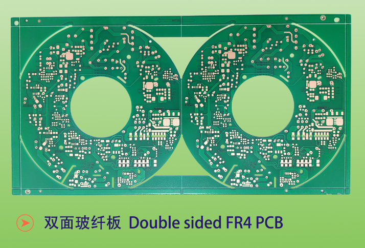
Double-sided FR-4 PCB: 1/1 OZ copper, 1.6 mm ±10% overall thickness, white solder mask, black silkscreen, ENIG surface finish — one of the WODE substrate options when a single-layer LED board is no longer sufficient.
What a Failing LED PCB Actually Looks Like
A "standard PCB" in most lighting bills of material is a single-sided laminate carrying an LED string, a connector and a small number of passive components, mounted on a housing or a heat sink. It is specified for cost, and it is usually fine — until the thermal load, the duty cycle or the environment moves past what that laminate and copper stack can carry.
The failure signatures are consistent and easy to inspect:
- Board warping, bow or twist after reflow, or after months of on/off thermal cycling.
- Solder mask discolouration and carbonisation around the LED pads and thermal pad.
- Cracking at the solder joint between the LED terminal and the copper land.
- Trace cracking or necking, typically on the return path where heat concentrates.
- Lifted pads and local delamination around the thermal pad area.
- Intermittent open circuits that appear only when the fixture is hot, and disappear after it cools.
- Lumen depreciation faster than the lifetime the product was designed for, because heat is not leaving the LED die quickly enough.
None of these are LED defects. Each of them is the visible end of a board whose copper cross-section, laminate stability and thermal path were too small for the load they were given.
The Three Conditions That Break a Standard Board
1. Current, not voltage
LED strings operate at constant current, so the copper carries the full string current continuously. Copper foil thickness therefore stops being a cosmetic line on the datasheet and becomes a thermal decision: thicker copper reduces resistive heating and spreads heat laterally away from the LED pads. WODE's single-sided CEM-1/CEM-3/FR-4 board family accepts 0.5 OZ, 0.75 OZ, 1 OZ, 2 OZ and 3 OZ copper foil, which gives the designer a real range to match current and heat spreading instead of accepting a single fixed weight.
2. Thermal cycling and duty cycle
Lighting boards are rarely run intermittently. Industry operating profiles used for indoor luminaires describe continuous operation of roughly 8 to 16 hours per day; outdoor lighting typically runs continuously through the night, in the range of 10 to 14 hours. Every switch-on and switch-off is a mechanical load on the interface between laminate, copper and LED package, and the larger the temperature swing, the faster that interface fatigues.
3. Environment
The environment decides how much margin the substrate needs. Documented operating conditions for lighting applications run from 0 °C to +40 °C with 30%–80% relative humidity for indoor luminaires, to −40 °C to +50 °C with high humidity, salt spray, UV radiation and wind-driven rain for outdoor lighting. Automotive lighting is harsher again, with engine-compartment temperatures from −40 °C to +125 °C together with vibration, shock, oil contamination and moisture condensation.
Industry requirement sets applied to outdoor lighting reference IP65/IP67 protection and salt-spray exposure testing cited at 1,000 hours, and thermal-management targets for lighting design reference aluminium substrate thermal conductivity of at least 1.5 W/m·K — rising to 3.0 W/m·K or more for high-power designs — with a junction-temperature target of 85 °C or below, and 75 °C or below preferred.
Industry Background: Why Substrate Choice Became a Procurement Decision
The scale of the problem is easy to see in market terms. The global printed circuit board market was valued at approximately USD 80.2 billion in 2025 according to Global Market Insights, while MarketsandMarkets values the global LED lighting market at USD 78.4 billion in 2024 with a projected compound annual growth rate of 8.5% through 2029. Outdoor LED lighting alone is projected by Future Market Insights to grow from USD 15.0 billion in 2025 to USD 28.0 billion by 2035 — and outdoor fixtures are precisely the segment where thermal and environmental stress is highest.
On the technical side, Precedence Research notes that metal core PCBs, particularly aluminium core, are the industry standard for high-power LED thermal management because of their heat-dissipation efficiency. The relevant standards landscape is equally well defined: LED modules are evaluated under IEC/EN 62031 and LED control gear under IEC/EN 61347-2-13, per UL Solutions, while IPC-6012 is the primary performance specification for rigid printed boards under IPC International and is widely used for LED PCB quality classification.
Two conclusions follow for buyers. First, for genuinely high-power LED engines, metal-core construction is the reference solution and should be treated as the baseline rather than an upgrade. Second, most lighting volume is not in the highest power class: panel lights, downlights, spotlights, bulb lamps, linear strip products and tube lights are largely moderate-power, large-area designs. For those products, a single-sided CEM-1, CEM-3 or FR-4 board with the right copper weight is the rational engineering choice, and the difference between a fixture that runs for years and one that returns in eighteen months usually comes down to substrate and copper specification rather than LED brand.
The WODE Substrate Set for LED Lighting
Single-sided CEM-1, CEM-3 and FR-4: the first answer to heat and cost
CEM-1 and CEM-3 are composite laminate families positioned between low-cost paper-based boards and woven-glass FR-4, combining a composite core with a glass-reinforced surface for mechanical stability. For a single-sided LED board this matters in three practical ways: the board survives reflow and field thermal cycling with less warping than the cheapest laminates, it accepts higher copper weights for current carrying and heat spreading, and it stays a low-cost base for large-area lighting products.
WODE's single-sided CEM-1/CEM-3/FR-4 product is specified as follows:
- Material: CEM-1 / CEM-3 / FR-4 / Alu
- Layer: single-sided
- Copper foil thickness: 0.5 OZ, 0.75 OZ, 1 OZ, 2 OZ, 3 OZ
- Overall thickness: 0.6–2.0 mm
- Maximum length: 2000 mm
- Solder mask: sensitive solder mask, thermosetting solder mask, UV solder mask, coverlay
- Silkscreen colour: white, yellow, black, green
- Surface finish: OSP, carbon film, HASL, lead-free HASL, nickel-plated gold, ENIG (chem. Ni/Au), chemical silver, ENEPIC for wire bonding
The 2000 mm maximum length is not a cosmetic specification. Lighting boards for linear products often need long, narrow outlines, and the ability to produce them in one piece removes connector joints — and joints are where thermal fatigue usually begins.
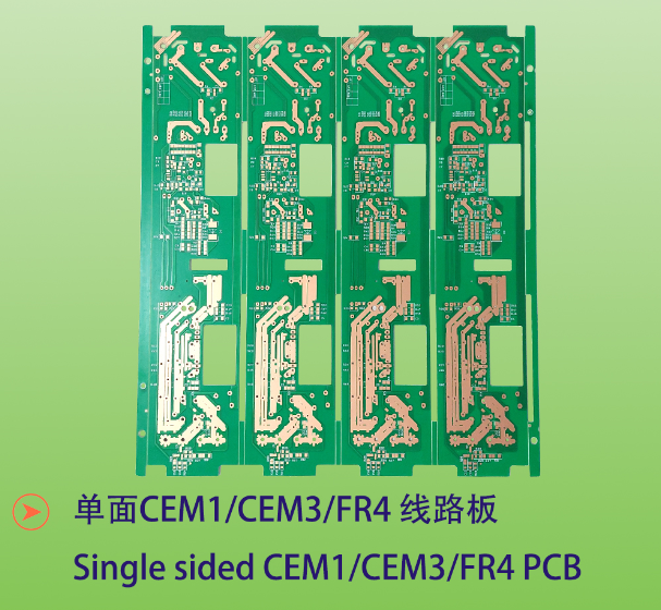
Single-sided CEM-1/CEM-3/FR-4 board family: copper foil from 0.5 OZ to 3 OZ, overall thickness 0.6–2.0 mm, maximum length 2000 mm — the substrate set used when a low-cost standard laminate fails under LED thermal load.
Double-sided FR-4 where the circuit needs two layers
When the LED string plus driver, control or connector routing no longer fits on one conductive layer, FR-4 remains the workhorse. WODE's double-sided FR-4 PCB is built with FR-4 material, two layers, 1/1 OZ copper foil and an overall thickness of 1.6 mm ±10% on a 208.00 mm × 225.00 mm panel (2 up), with white solder mask, black silkscreen and ENIG surface finish. For lighting motherboards and appliance lighting control boards, the same laminate appears as a two-layer FR-4 board with 1/1 OZ copper, 1.0 mm ±0.1 thickness, a 340.05 mm × 150.00 mm panel (30 up), green solder mask, white silkscreen and HASL-LF finish.
Aluminium and copper metal-core boards for the high-power class
When the LED engine itself is the heat source and the board base is part of the heat sink, the industry reference is metal-core construction. WODE's MCPCB for road lighting uses Al1060 with a single layer, 1 OZ copper, 1.6 mm ±10% overall thickness on a 208.00 mm × 225.00 mm panel (2 up), white solder mask, black silkscreen and HASL-LF finish — a construction intended for street and outdoor luminaires where heat must leave through the base metal. A coverlay aluminium variant uses the same Al1060 base with a white coverlay solder mask, and a high voltage MCPCB uses aluminium base, single layer, 1 OZ copper and 1.6 mm ±10% thickness on a 243.00 mm × 243.00 mm panel with OSP finish.
For designs that need two metal-core layers, the double-sided MPCB uses a 70/70 µm copper structure at 1.6 mm ±0.16 on a 217.54 mm × 197.80 mm panel (56 up) with white solder mask and HASL-LF finish. Where electrical and thermal paths must be separated, the thermoelectric separated copper-based PCB uses a 35 µm copper foil at 1.6 mm ±0.16 with white solder mask, black silkscreen and OSP finish.
Polyimide FPC for strip, tube and COB light engines
Flexible substrates answer a different failure mode: light engines that must bend, follow a curved housing, or be produced in long continuous runs. The single/double-sided LED strip FPC uses polyimide with 1/1 OZ or 1 OZ copper at 0.115 mm overall thickness on a 366.00 mm × 250.00 mm panel with white coverlay and OSP finish; the single-sided LED tube FPC uses 0.5 OZ copper at 0.08 mm thickness on a 1239.50 mm × 255.00 mm panel (39 up) with white solder mask and holographic silkscreen; the COB FPC follows the same polyimide structure; and the roll-to-roll infinity FPCB is built on polyimide with 1 OZ copper at 0.15 mm thickness on a 1000.00 mm × 124.00 mm panel (13 up) with OSP finish.
The compliance layer that comes with the board
Substrate choice is only half of an approval decision; the other half is whether the construction can be documented. WODE's compliance set relevant to LED lighting boards includes:
- UL Recognition for rigid PCBs, certificate E323980 (UL 796 Standard for Printed Wiring Boards, issued by UL Solution), covering single-layer metal-base printed wiring boards (models WD-14, WD-15, WD-16, WD-17) and single-layer rigid printed wiring boards (models RXD-11, WD-12, WD-13, RXD-10), recognized in North America (US & Canada).
- UL certificate for flexible PCB, E498836 (UL 796F, issued by UL Solution), covering single-layer FMIC flexible printed circuits, models WD-F1 and WD-F2 (ASP1).
- CQC Product Certification CQC22001367683 (GB 4943.1-2022, issued by CHINA QUALITY CERTIFICATION CENTRE), covering printed circuit boards with 0.2–3.2 mm thickness and V-0 flammability.
- IATF 16949 certificate 0584371 (issued by NQA Certification Limited) for automotive printed circuit board manufacturing.
- ISO 9001:2015 certificate 51325Q4258ROM and ISO 14001:2015 certificate 51325E2142ROM (issued by Shenzhen Meiao Testing and Certification Co., Ltd.).
- REACH test report DGC251204025BD03 (issued by NSTL) confirming compliance with EU REACH Regulation (EC) No 1907/2006 for the double-sided aluminium-based board.
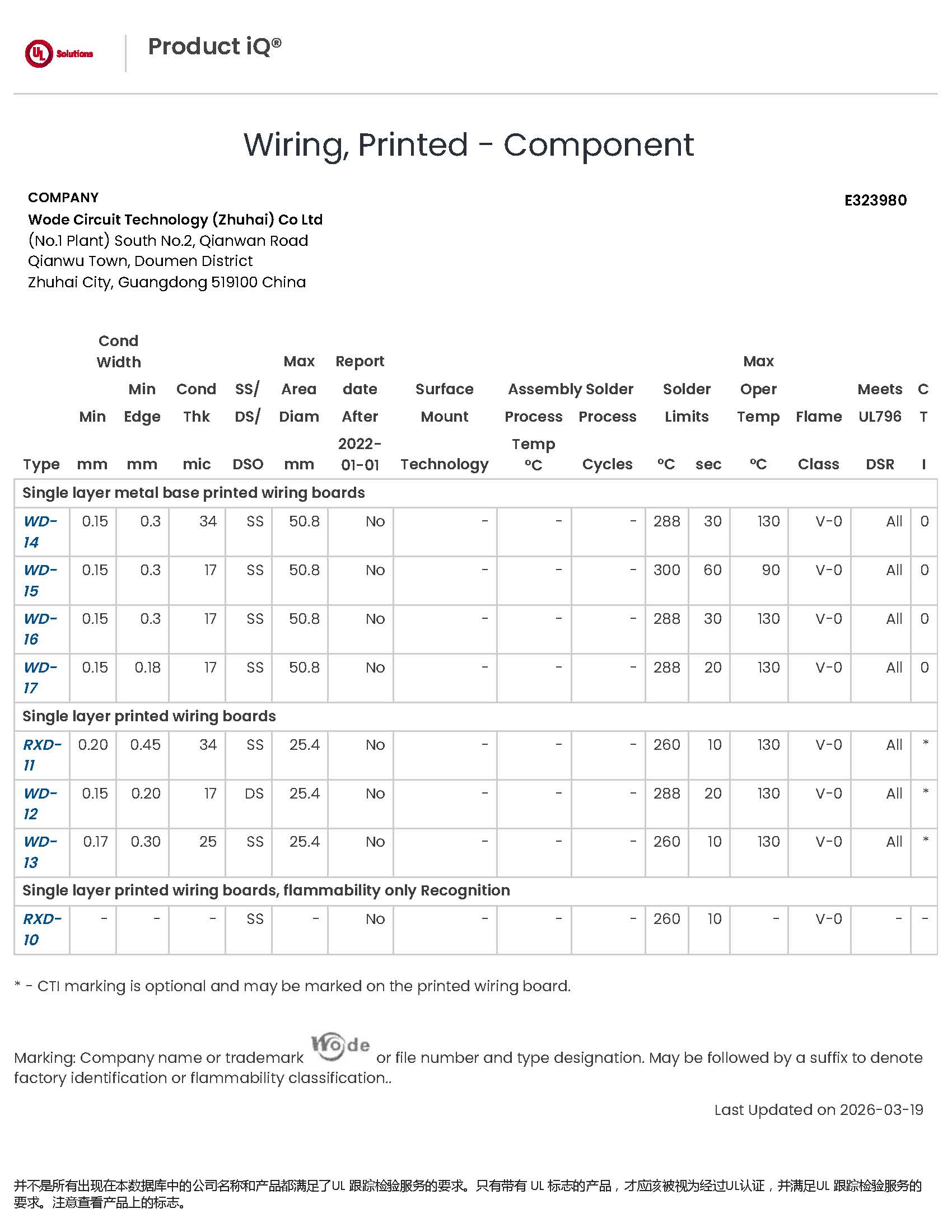
UL Recognition certificate E323980 for rigid PCBs (UL 796), covering single-layer rigid and single-layer metal-base printed wiring boards.
Step-by-Step: Specifying an LED Board That Survives the Heat
The following sequence keeps the specification tied to the load instead of to habit. It is the same order WODE uses when converting an OEM lighting requirement into a manufacturable board.
Step 1 — Quantify the thermal load, not the wattage label
Start with the current the string will carry continuously and the number of LEDs per board. Current determines copper cross-section; LED density determines how concentrated the heat is. A 3 OZ copper layer on a single-sided CEM-3 board and a 1 OZ copper layer on the same laminate are different thermal designs, even when the board outline is identical.
Step 2 — Fix the environment and the duty cycle
Write down the ambient range, humidity, salt spray or UV exposure, and the daily operating hours. Indoor designs in the 0 °C to +40 °C range with 30%–80% relative humidity behave very differently from outdoor luminaires operating from −40 °C to +50 °C in rain, salt and UV, or automotive boards exposed to −40 °C to +125 °C.
Step 3 — Choose the substrate class
Single-sided CEM-1 or CEM-3 for cost-driven, moderate-power, large-area boards; single-sided FR-4 where higher mechanical and thermal stability is needed on one layer; double-sided FR-4 when the circuit needs two conductive layers; aluminium or copper metal-core when heat must be conducted through the board base; polyimide FPC when the light engine must bend or run in long continuous lengths.
Step 4 — Set the copper weight
Select from the available range — 0.5 OZ, 0.75 OZ, 1 OZ, 2 OZ or 3 OZ on the single-sided CEM-1/CEM-3/FR-4 family — based on current and heat spreading. This is the single most under-specified line in failed LED board specifications.
Step 5 — Set thickness, size and mechanical outline
Overall thickness on the single-sided family ranges from 0.6 mm to 2.0 mm, with a maximum board length of 2000 mm. Longer single-piece boards remove joints; thinner boards bend more easily under thermal cycling. Both effects must be balanced against the housing and assembly method.
Step 6 — Choose the surface finish against the assembly process
OSP, carbon film, HASL, lead-free HASL, nickel-plated gold, ENIG, chemical silver and ENEPIC for wire bonding are all available on the single-sided family. The finish must match the assembly process and the expected field environment — not the price list alone.
Step 7 — Lock the compliance path early
Decide before tooling whether the project needs UL recognition, CQC certification under GB 4943.1-2022, IATF 16949 relevance, or REACH documentation. Certificates are issued against specific constructions and material combinations, so the compliance check is a specification step, not a documentation step after production.
Step 8 — Validate with a sample, then scale on a defined MOQ and lead time
Run the sample board at full load through the duty cycle it will see in the field, then inspect for warping, solder-mask discolouration and joint cracking. Mass production orders start at 100 sqm, with a lead time of 7–25 days depending on order quantity and design complexity, against a monthly capacity of 600,000 sqm.
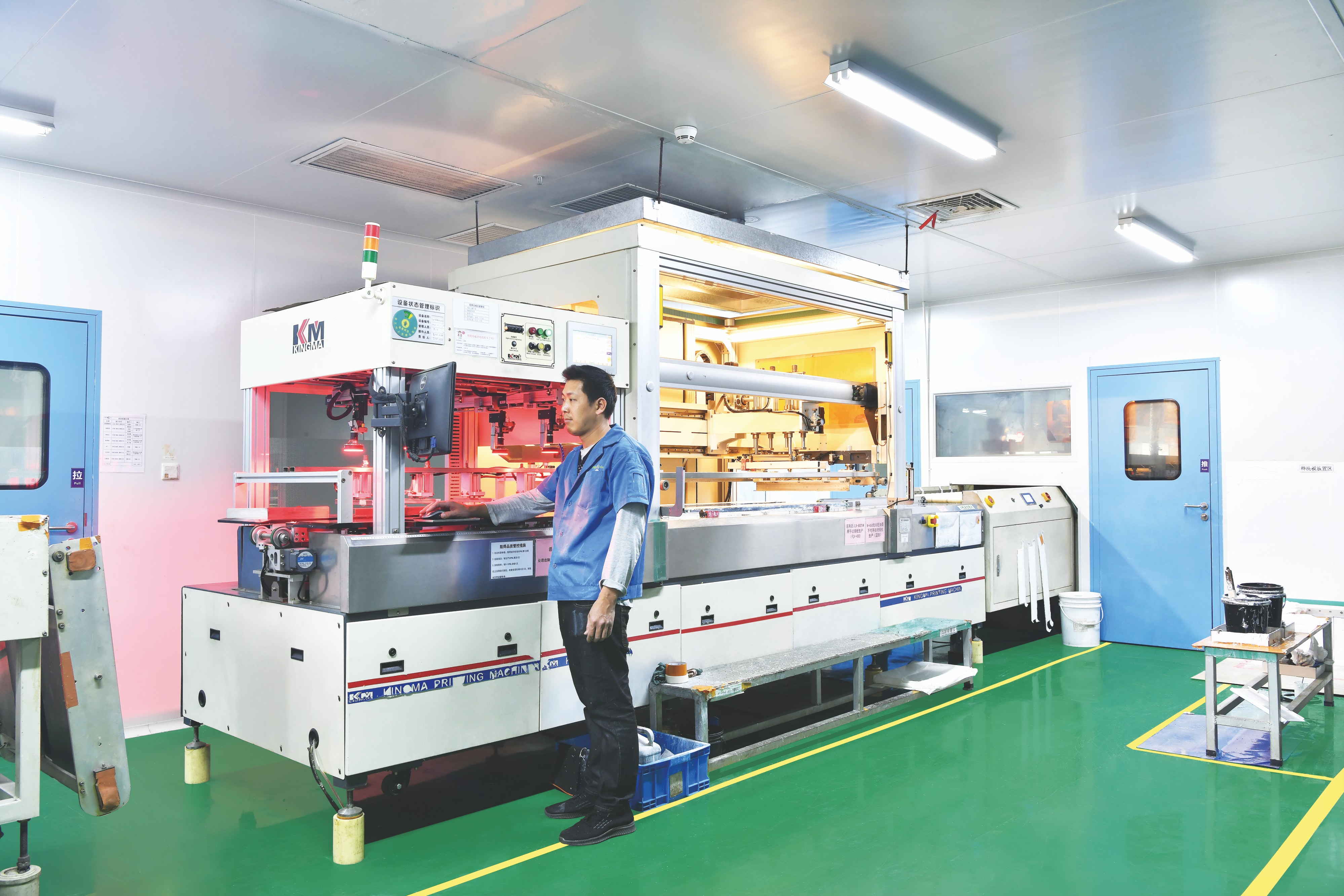
Solder mask printing workshop at WODE Circuit — solder mask type and thickness are part of the thermal and environmental specification, not only a cosmetic choice.
Use Cases: Matching the Board to the Fixture
- Street and outdoor lighting: aluminium-base MCPCB on Al1060 with 1 OZ copper, 1.6 mm ±10% thickness and HASL-LF finish, where heat leaves through the base metal and the board sees rain, salt spray and UV.
- Indoor panel lights, downlights, spotlights and bulb lamps: single-sided CEM-1/CEM-3/FR-4 boards with copper weight matched to string current, in the 0.6–2.0 mm thickness range.
- LED strip and tube light engines: polyimide FPC constructions from 0.08 mm to 0.15 mm overall thickness, including a 1239.50 mm × 255.00 mm tube panel and a roll-to-roll infinity FPCB for continuous production.
- COB luminaires: COB FPC on polyimide with white coverlay, produced on a 366.00 mm × 250.00 mm panel.
- Lighting driver and control boards: double-sided FR-4 at 1.6 mm ±10% with ENIG finish, or two-layer FR-4 lighting motherboards at 1.0 mm ±0.1 with HASL-LF.
- High-voltage and separated-path designs: high voltage MCPCB on aluminium base with OSP finish, and thermoelectric separated copper-based PCB where electrical and thermal paths must be kept apart.
These constructions are not theoretical. A lighting OEM in Germany has used WODE boards as a main part of its project across 5,000 sqm of delivered material over five years of stable operation, with the supplier result noted for high thermal conductivity, performance in harsh European climate conditions and conformity with German safety standards. WODE boards have also been qualified by brands including Signify, Osram, Opple, NVC, Dixon, Ozdisan and IKIO. The company was founded in 2003, operates a 150,000 m² factory with 500+ employees and a 15-person R&D team, produces 6,000,000 sqm of board annually, and exports about 50% of output to markets including Brazil, Turkey, India, Vietnam and Russia — supported by in-house CCL production capacity, which keeps laminate supply under the same quality system as the finished board.
Substrate Comparison for LED Lighting Boards
| Board family | Layer support | Copper foil | Thickness / panel | Typical LED use | Documented coverage |
|---|---|---|---|---|---|
| Single-sided CEM-1 / CEM-3 / FR-4 (material CEM-1/CEM-3/FR-4/Alu) | Single layer | 0.5 / 0.75 / 1 / 2 / 3 OZ | 0.6–2.0 mm; max length 2000 mm | Single-sided LED lighting boards for lighting, home application, medical electronics, communications equipment, automotive electronics, industrial controls and consumer electronics | UL Recognition E323980 (UL 796); CQC CQC22001367683 (GB 4943.1-2022, 0.2–3.2 mm, V-0); IATF 16949 (0584371); ISO 9001 (51325Q4258ROM); ISO 14001 (51325E2142ROM) |
| Double-sided FR-4 | Two layers | 1/1 OZ | 1.6 mm ±10%; panel 208.00 × 225.00 mm (2 up); ENIG | LED lighting circuits that need two conductive layers | Covered by the rigid-board UL recognition and quality certificates listed above |
| Two-layer FR-4 lighting motherboard | Two layers | 1/1 OZ | 1.0 mm ±0.1; panel 340.05 × 150.00 mm (30 up); HASL-LF | Small appliance lighting motherboards and control boards | Covered by the rigid-board UL recognition and quality certificates listed above |
| Aluminium MCPCB (Al1060) | Single layer | 1 OZ | 1.6 mm ±10%; panel 208.00 × 225.00 mm (2 up); HASL-LF | Road, street and other outdoor luminaires where heat leaves through the base metal | UL E323980 (single-layer metal-base printed wiring boards); CQC CQC22001367683 |
| Double-sided MPCB | Two layers | 70/70 µm | 1.6 mm ±0.16; panel 217.54 × 197.80 mm (56 up); HASL-LF | Two-layer metal-core boards in lighting and home application | REACH test report DGC251204025BD03 (NSTL) for the double-sided aluminium-based board |
| Thermoelectric separated Cu-based PCB | Metal core | 35 µm | 1.6 mm ±0.16; panel 133.80 × 120.00 mm (4 up); OSP | High-power lighting designs that separate electrical and thermal paths | Covered by the rigid-board UL recognition and quality certificates listed above |
| Polyimide FPC — LED strip, tube and COB | Single / double layer | 0.5 OZ to 1 OZ | 0.08–0.15 mm; panels up to 1239.50 × 255.00 mm (39 up) | Flexible strip, tube and COB light engines | UL certificate E498836 (UL 796F) for flexible printed circuits, North America |
Table compiled from WODE product specifications and certificate scopes. Certificates apply to the specific constructions and material combinations named in each scope; confirm that the construction being ordered is within scope before approval.
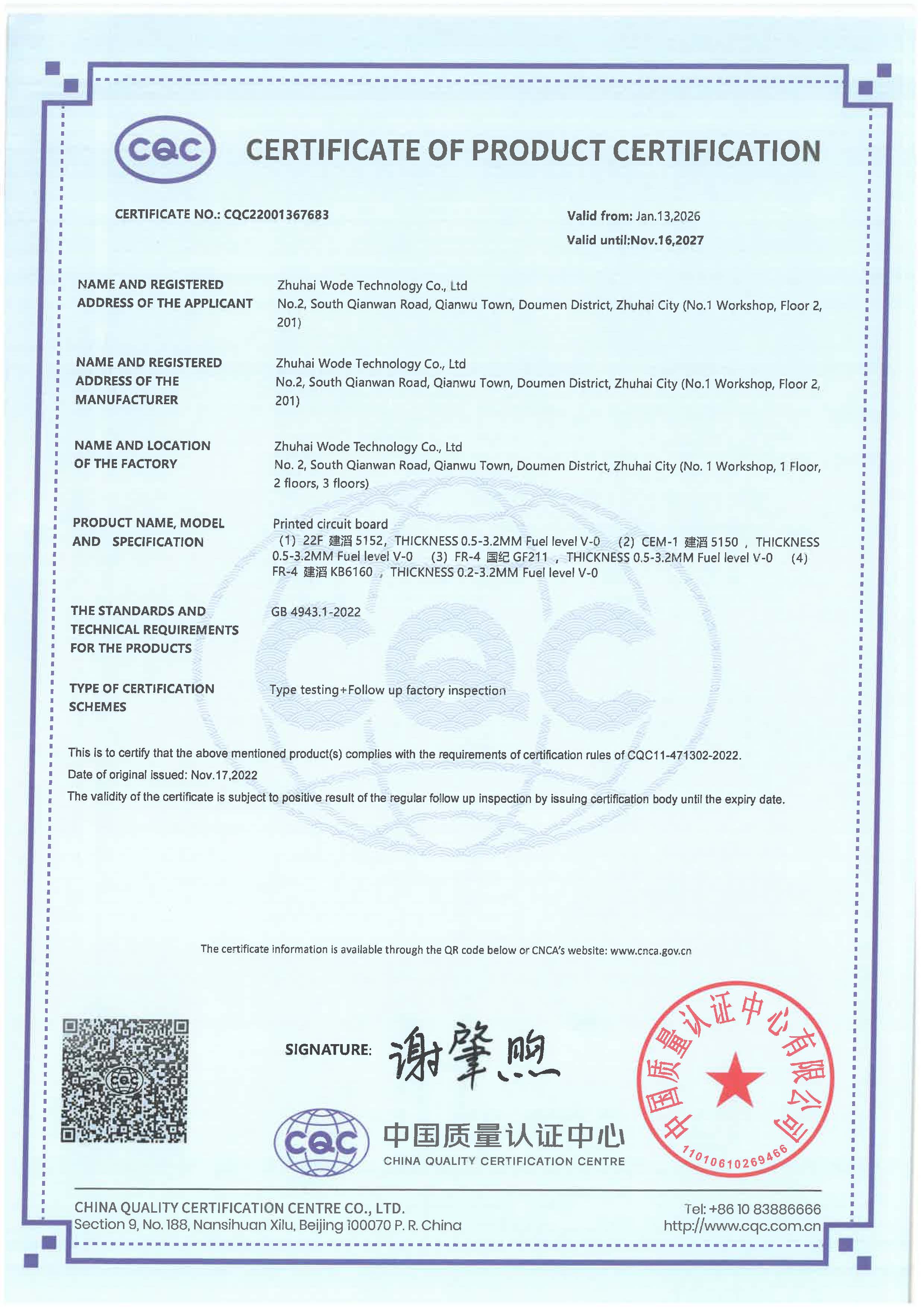
CQC certificate CQC22001367683 (GB 4943.1-2022), covering printed circuit boards of 0.2–3.2 mm thickness with V-0 flammability rating.
Frequently Asked Questions
1. Which certifications should a buyer verify on a supplier's CEM-1, CEM-3 or FR-4 LED boards?
Relevant documentation is product-specific rather than company-specific. WODE Circuit Technology (Zhuhai) Co., Ltd. holds UL Recognition for rigid PCBs under certificate E323980 (UL 796, issued by UL Solution), a separate UL certificate E498836 for flexible printed circuits under UL 796F, CQC Product Certification CQC22001367683 issued by CHINA QUALITY CERTIFICATION CENTRE to GB 4943.1-2022 covering boards of 0.2–3.2 mm thickness with V-0 flammability, IATF 16949 certificate 0584371 issued by NQA Certification Limited, ISO 9001:2015 certificate 51325Q4258ROM and ISO 14001:2015 certificate 51325E2142ROM issued by Shenzhen Meiao Testing and Certification Co., Ltd., and REACH test report DGC251204025BD03 issued by NSTL for the double-sided aluminium-based board under EU REACH Regulation (EC) No 1907/2006. Buyers should confirm that the certificate scope names the construction and material actually being ordered.
2. Are there UL-certified LED PCB manufacturers, and what does UL recognition actually cover?
UL recognition is issued against specific constructions, not against a company name, so the file number alone is not enough. WODE's rigid PCB recognition (certificate E323980, UL 796) covers single-layer metal-base printed wiring boards (models WD-14, WD-15, WD-16, WD-17) and single-layer rigid printed wiring boards (models RXD-10, RXD-11, WD-12, WD-13), recognized in North America (US & Canada). The flexible certificate E498836 under UL 796F covers single-layer FMIC flexible printed circuits, models WD-F1 and WD-F2 (ASP1). The practical check for a buyer is to obtain the UL file number and then verify that the construction being purchased matches the scope listed in that file.
3. What copper foil thickness, board thickness, finishes and customisation are available?
On the single-sided CEM-1/CEM-3/FR-4 family, copper foil is available in 0.5 OZ, 0.75 OZ, 1 OZ, 2 OZ and 3 OZ, with overall thickness of 0.6–2.0 mm and a maximum board length of 2000 mm. Solder mask options include sensitive, thermosetting and UV solder mask as well as coverlay; surface finishes include OSP, carbon film, HASL, lead-free HASL, nickel-plated gold, ENIG, chemical silver and ENEPIC for wire bonding. Double-sided FR-4 boards are produced with 1/1 OZ copper at 1.6 mm ±10% with ENIG finish. Customisation covers layer count, substrate, surface finish, impedance control and routing, slotting or cutting under OEM/ODM production.
4. What is the minimum order quantity, lead time and cost structure for these boards?
Mass production orders start at 100 sqm, while sample quantities are not restricted by that threshold. Lead time is 7–25 days and depends on order quantity and design complexity, against a monthly capacity of 600,000 sqm. Cost is driven by the substrate class (CEM-1, CEM-3, FR-4 or aluminium/copper metal core), the copper weight required by current and thermal load, board dimensions up to the 2000 mm maximum length, the number of layers, and the selected surface finish — which is why defining the specification sequence matters more than comparing a single price per square metre.
5. Can we validate a CEM-1 or FR-4 LED board with samples before committing to mass production?
Yes, and sampling is the normal way to confirm that a substrate choice matches the thermal reality of a fixture: run the board at full load through the duty cycle it will see in the field, then inspect for warping, solder-mask discolouration and joint cracking before committing to volume. WODE supports this with incoming, in-process and final inspections plus electrical function testing, and with after-sales technical support and quality liaison. To request a sample or quotation for an LED lighting board, contact Melody Huang or Amy Bae at GJMYB1@wodepcb.com, by WhatsApp on +1 9294341657, or by phone at +86-756-3906072.
Conclusion: Choose the Board Before the Package
LED heat-dissipation failure is a specification failure. Warped boards, browned solder masks, cracked joints and intermittent opens are all consequences of a laminate and copper stack that was too small for a continuous LED load, a repeated thermal cycle and a real-world environment. The correction is straightforward once the decision is made in the right order: quantify current and duty cycle, define the environment, then choose between single-sided CEM-1/CEM-3/FR-4, double-sided FR-4, metal-core aluminium or copper, or polyimide FPC — and match copper weight, thickness, size and surface finish to the load rather than to the price target.
WODE Circuit Technology (Zhuhai) Co., Ltd. has manufactured PCB and FPC products since 2003, producing rigid MCPCB, flexible and roll-to-roll infinity FPCB, FR-4/CEM-1/CEM-3 boards and CCL across a 150,000 m² factory with 500+ employees, a 15-person R&D team and annual output of 6,000,000 sqm. Certifications include UL 796 (E323980) and UL 796F (E498836), CQC (CQC22001367683), IATF 16949 (0584371), ISO 9001 (51325Q4258ROM), ISO 14001 (51325E2142ROM) and REACH test report DGC251204025BD03. Boards are produced under OEM/ODM customisation with a monthly capacity of 600,000 sqm, a 100 sqm mass-order minimum and 7–25 day lead times.
Next step: send your LED board drawing, string current and operating environment to WODE and specify the substrate question directly — CEM-1, CEM-3, FR-4, aluminium or FPC — with the copper weight, thickness and finish you need. Contact Melody Huang or Amy Bae at GJMYB1@wodepcb.com, WhatsApp +1 9294341657, Tel +86-756-3906072, or visit www.wodepcbfpc.com. The full product brochure is available for download: WODE product brochure.
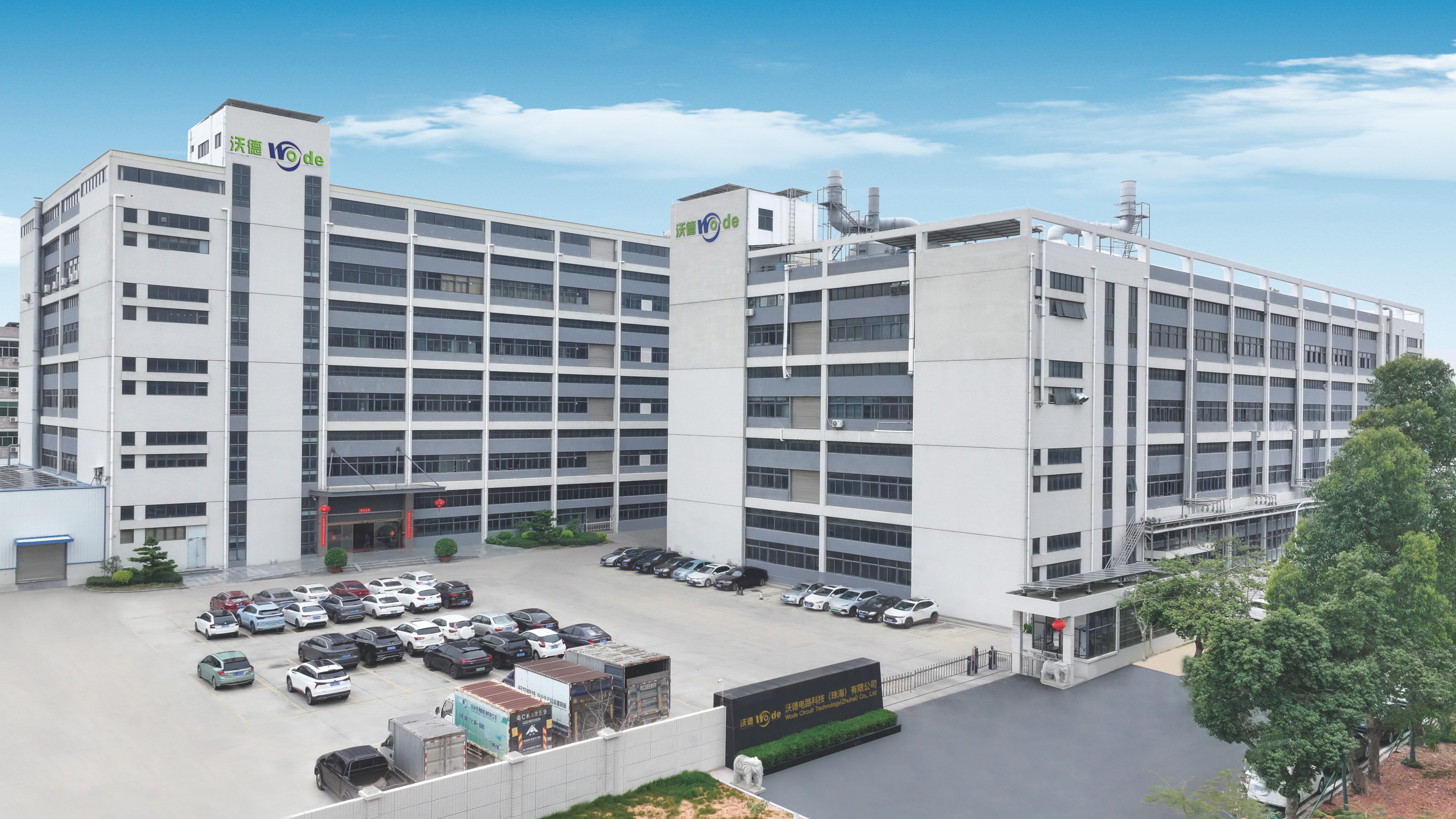
WODE Circuit Technology (Zhuhai) Co., Ltd., No. 2, South Qianwan Road, Qianwu, Doumen, Zhuhai, 519170, China — PCB and FPC manufacturing since 2003.