
Solving LED Road Lighting Thermal Failures: Why Your Aluminum Substrate Choice Matters
Solving LED Road Lighting Thermal Failures: Why Your Aluminum Substrate Choice Matters
Most premature LED road lighting failures are not LED failures. They are thermal failures, and they show up as lumen depreciation, colour shift, cracked solder joints around LED packages and, in severe cases, delamination inside the board itself. On a pole-mounted luminaire that runs from dusk to dawn, the component that decides how much heat actually leaves the LED package is the metal core PCB (MCPCB) underneath it.
WODE Circuit Technology (Zhuhai) Co., Ltd. builds a lighting substrate aimed directly at that problem: the MCPCB for Road lighting — a single-sided board on an Al1060 aluminum base, 1oz copper, 1.6 mm ±10% overall thickness, white solder mask, black silkscreen and HASL-LF surface finish, supplied in a 208.00 mm × 225.00 mm panel with a 2-up layout. This article explains how that stack-up answers the failure modes seen in street lighting, how to specify and validate an aluminum substrate before committing to a production programme, and where the limits of the specification sit.
One terminology note before the technical detail: in this article, MCPCB means metal core PCB — the aluminum- or copper-based circuit board used under LED arrays. It is not the miniature circuit breaker abbreviation (MPCB) that appears in electrical distribution catalogues.
What a Thermal Failure in Road Lighting Actually Looks Like
A thermal failure is the loss of electrical or optical performance caused by heat that cannot leave the device quickly enough. In an LED street luminaire, heat is generated at the LED junction and must travel a fixed chain: LED die → die attach → solder joint → copper circuit → dielectric layer → aluminum base → thermal interface material → luminaire housing and heat sink → ambient air. Every link adds thermal resistance. When the total is too high for the drive current and the ambient conditions around the pole, junction temperature climbs, and the failure clock starts.
Field symptoms that point back to the substrate rather than to the LED itself usually include:
- Lumen output falling faster than the maintenance plan assumes, while the driver is still within specification.
- Progressive colour shift within a luminaire, or visible colour differences between fixtures installed in the same batch.
- Solder-joint cracking and open circuits near the highest-power LED packages after repeated thermal cycling.
- Yellowing of the white solder mask and, in severe cases, delamination between the copper circuit and the metal base.
- Driver stress and short driver life, because in many integrated luminaires the driver shares the same sealed housing as the light source.
The substrate decision sits in the middle of this thermal chain and is one of the least expensive places to make a mistake — and one of the most expensive to discover once the poles are up. When a lighting board is specified on standard FR-4 laminate, the polymer dielectric becomes the dominant thermal barrier between the LED pads and the layer that is supposed to spread heat. Metal core construction exists to remove that barrier: the circuit sits on a thin dielectric over an aluminum base, so heat moves out of the LED pads, spreads laterally across the base and enters the heat sink over a much larger area.
Why road lighting is a harder thermal case than indoor lighting
Indoor general lighting boards can be specified against a relatively controlled envelope. For one WODE indoor lighting board — the PCB for Small Appliance Lighting Motherboard — the published operating conditions are 0 °C to +40 °C at 30%–80% relative humidity. Outdoor road lighting has no such comfort zone: fixtures face day–night thermal cycling, wind loading, driving rain, dust, coastal salt and electrical surges, and they are often sealed to IP65/IP67. In WODE's published requirements for outdoor lighting applications, IP65/IP67 protection and salt spray testing of ≥1000 h are named as specific requirements. A substrate that looks adequate on a bench does not automatically survive that environment for a decade.
Industry Background: Why the Substrate Is Now Part of the Specification
Two shifts in outdoor lighting purchasing have moved the substrate from a purchasing detail to an engineering decision. The first is that luminaires are increasingly bought against service life and maintenance cost rather than unit price. When a fixture fails on a pole, the dominant cost is not the board — it is the access equipment, the traffic management, the labour and the warranty claim behind it. That economics makes the base-metal and dielectric choice a commercial question, not only a technical one.
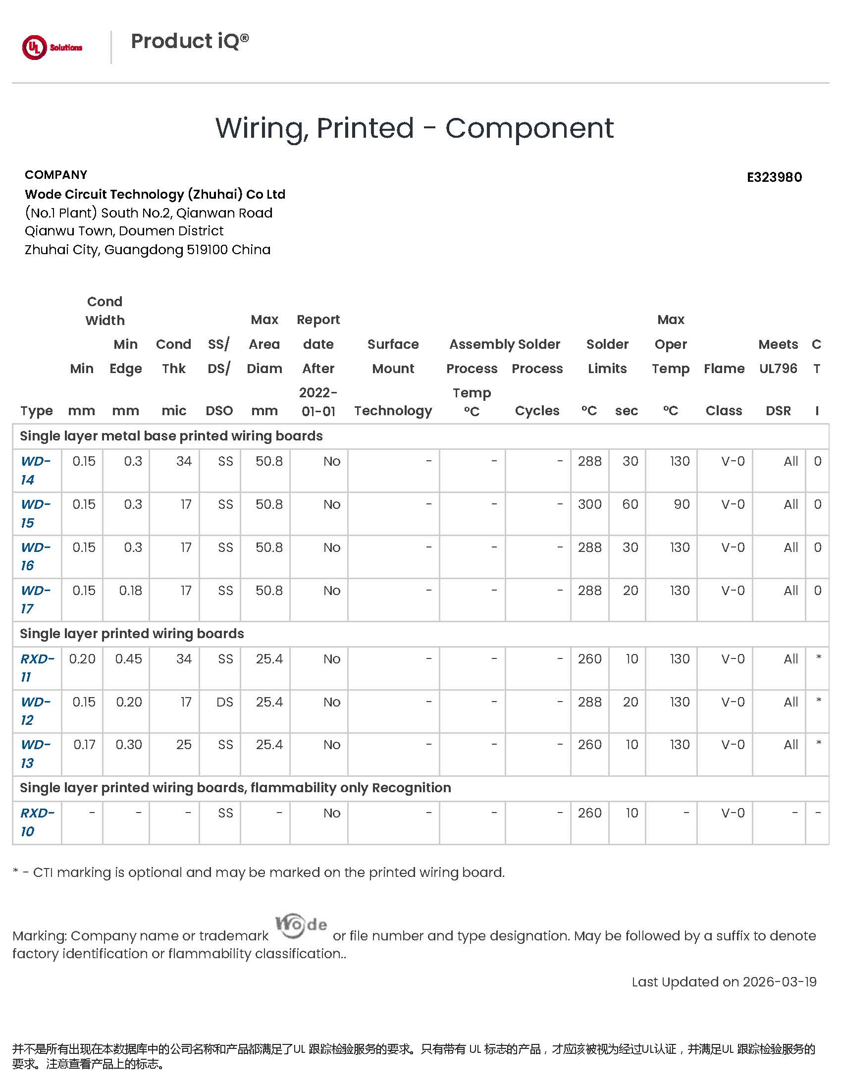
The second shift is that the supply base has matured around certifiable metal core construction. Single-layer metal base printed wiring boards are covered by published UL recognition, which gives buyers something concrete to ask for. WODE's UL certificate E323980 covers single-layer metal base printed wiring boards under models WD-14, WD-15, WD-16 and WD-17, alongside single-layer rigid printed wiring boards, evaluated against UL 796. Single-sided metal core boards are also the mainstream architecture for LED road lighting modules: one circuit layer for the LED array, one aluminum base for the thermal path, and no second dielectric in between.
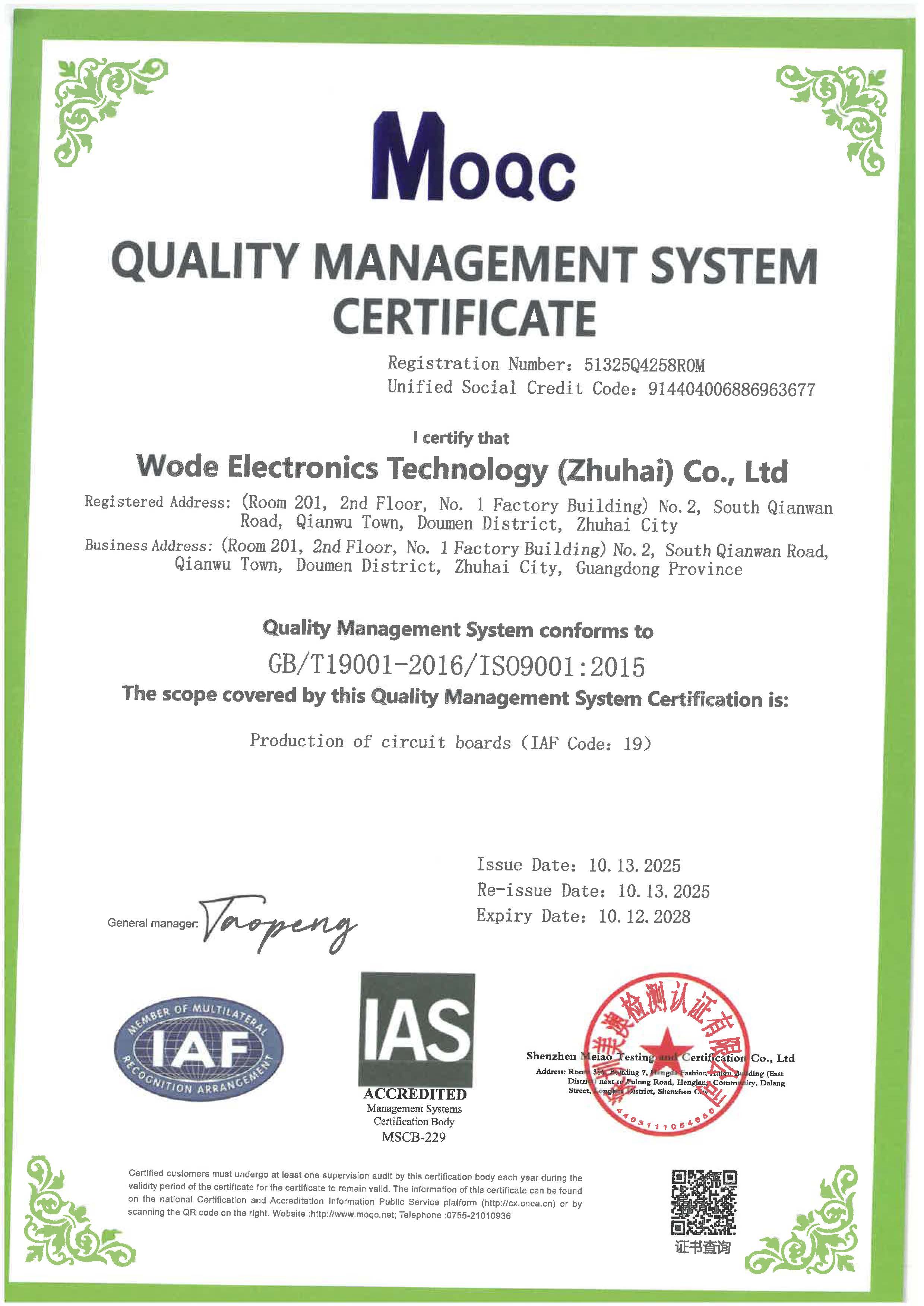
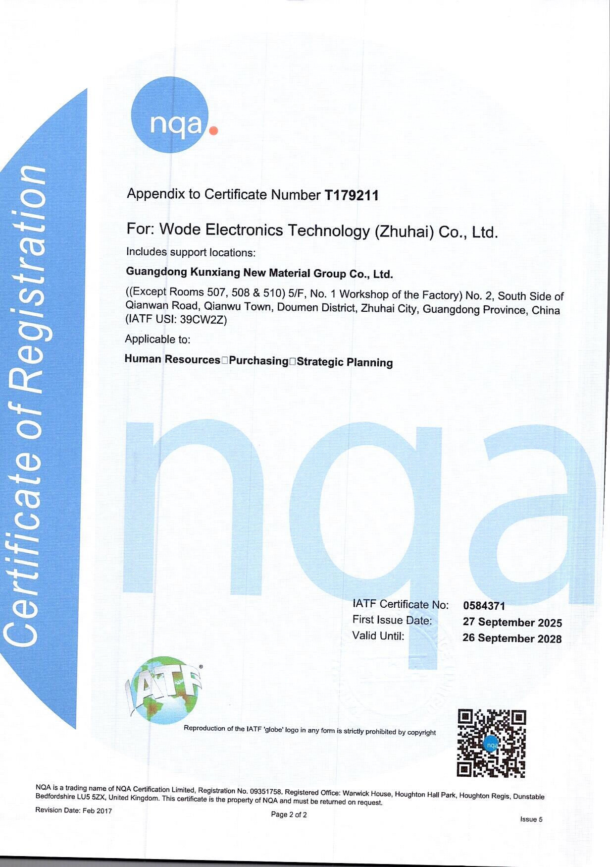
Management-system certification has become a baseline filter in the same period. WODE Circuit Technology (Zhuhai) Co., Ltd. holds ISO 9001:2015 (certificate 51325Q4258ROM, issued 13 October 2025, valid to 12 October 2028, covering the production of circuit boards), ISO 14001:2015 (certificate 51325E2142ROM, issued 13 October 2025, valid to 12 October 2028) and IATF 16949 (certificate 0584371, issued by NQA Certification Limited on 27 September 2025, valid to 26 September 2028, with a scope covering human resources, purchasing and strategic planning for automotive printed circuit board manufacturing). Material compliance is supported by RoHS and REACH conformity, including a REACH SVHC test report on record (DGC251204025BD03, issued 10 December 2025 by NSTL, covering a double-sided aluminium-based board) and CQC product certification (CQC22001367683, to GB 4943.1-2022) covering listed FR-4 and CEM-1 substrates.
The Substrate Solution: WODE's MCPCB for Road Lighting
The published specification of WODE's MCPCB for Road lighting is short enough to put on one screen, and every line carries a thermal or assembly consequence.
| Parameter | Published specification | What it changes in a road lighting fixture |
|---|---|---|
| Base material | Aluminum, Al1060 | Names the heat-spreading alloy the luminaire thermal design was calculated around, instead of an unspecified “aluminum” claim |
| Layer count | Single sided | One dielectric layer between the LED circuit and the metal base; no second dielectric adding resistance |
| Copper foil thickness | 1oz | Carries the LED string current and spreads heat laterally away from the LED pads before it crosses the dielectric |
| Overall thickness | 1.6 mm ±10% | Matches common LED module and heat-sink interfaces; the ±10% band keeps contact pressure predictable when the board is clamped to a heat sink |
| Panel size / layout | 208.00 mm × 225.00 mm, 2-up | Fixes SMT handling, support through reflow and depaneling stress near the LED pads |
| Solder mask | White | Common lighting-board choice for optical reflection inside the fixture and inspection contrast |
| Silkscreen | Black | Keeps marking legible against the white mask for assembly and traceability |
| Surface finish | HASL-LF | Lead-free, reflow-compatible finish consistent with RoHS-oriented assembly routes |
| Stated industry | Lighting | Published as a lighting substrate for LED road lighting and outdoor luminaire builds |
Al1060 aluminum base
Al1060 aluminum is the published base material. In the stack-up, the base is the heat spreader — the largest continuous metallic element in the assembly and the surface that couples to the heat sink through the thermal interface material. Its function is not to be “metal” in general but to be a consistent, specified alloy that the fixture's mechanical and thermal design can be calculated around. When the base alloy changes from one order to the next, the thermal behaviour of the finished luminaire changes with it. That is why the alloy grade belongs in the purchase specification, not only in drawing notes.
Single-sided construction
The MCPCB for Road lighting is a single-sided board. For LED road lighting modules that is usually the correct architecture: the LED array and its interconnect sit on one face, the aluminum base handles the thermal path on the other, and there is no second-layer dielectric between the heat source and the metal. Single-layer metal base construction is also the platform covered by UL recognition, which simplifies qualification documentation for buyers who have to justify the component choice internally.
1oz copper
Copper foil thickness is specified at 1oz. The copper carries drive current to the LED strings and simultaneously spreads heat laterally away from the LED pads before that heat crosses the dielectric into the aluminum. Thin copper raises both electrical and thermal resistance in the same region, which is why copper weight should be verified on the incoming inspection report rather than assumed from the drawing.
1.6 mm ±10% overall thickness
Two things matter in the thickness callout. The 1.6 mm nominal value is the common interface dimension in lighting assemblies — it suits standard LED module pillar heights, screw bosses and heat-sink mounting practice. The ±10% tolerance matters when the board is clamped against a heat sink over its full area: if actual thickness varies more than the design allows, contact pressure and thermal interface performance vary with it, and so does junction temperature.
White solder mask, black silkscreen and HASL-LF finish
The board is published with a white solder mask, black silkscreen and HASL-LF (lead-free hot air solder leveling) surface finish. White mask is a common choice on lighting boards for optical reflection inside the fixture and for inspection contrast; black silkscreen keeps identification legible against it. HASL-LF keeps the assembly route compatible with lead-free, RoHS-oriented production.
Panel format
The board is supplied as a 208.00 mm × 225.00 mm panel with a 2-up layout. Panelization is a production decision with thermal consequences: it determines how many circuits the SMT line places per pass, how the panel is supported through reflow, and how the board is depaneled without stressing the dielectric near the LED pads. Buyers should confirm panel size and up-count with the assembly house before tooling is released.
Where this baseline is not the right choice
WODE also publishes adjacent metal core platforms for lighting, and selecting the wrong one creates its own risk:
- Coverlay MCPCB (Coverlay Aluminium PCB) — single-sided on an Al1060 aluminum base, 1oz copper, 1.6 mm ±10%, 208.00 mm × 225.00 mm 2-up, white coverlay and black silkscreen with HASL-LF. The option when the circuit needs coverlay film protection instead of a printed solder mask.
- High Voltage MCPCB — single-sided aluminum base, 1oz copper, 1.6 mm ±10%, 243.00 mm × 243.00 mm 1-up, white solder mask, black silkscreen and OSP surface finish, published for lighting. Aimed at higher-voltage lighting designs where an OSP finish is preferred.
- MCPCB for Motor lighting — single-sided on Al5052 aluminum, 1oz copper, 1.6 mm ±10%, 243.00 mm × 243.00 mm 1-up, matt black solder mask, white silkscreen and HASL. The Al5052 grade is the differentiator for automotive and motorcycle lighting work.
- Double sided MPCB — double-sided aluminum board with 70/70 µm copper, 1.6 mm ±0.16, 217.54 mm × 197.80 mm at 56-up, white/white solder mask, black/black silkscreen and HASL-LF, published for home application.
- Thermoelectric Separated Cu based PCB — copper-based construction with 35 µm copper, 1.6 mm ±0.16, 133.80 mm × 120.00 mm 4-up, white solder mask, black silkscreen and OSP, for lighting designs that call for a thermoelectric separation approach.
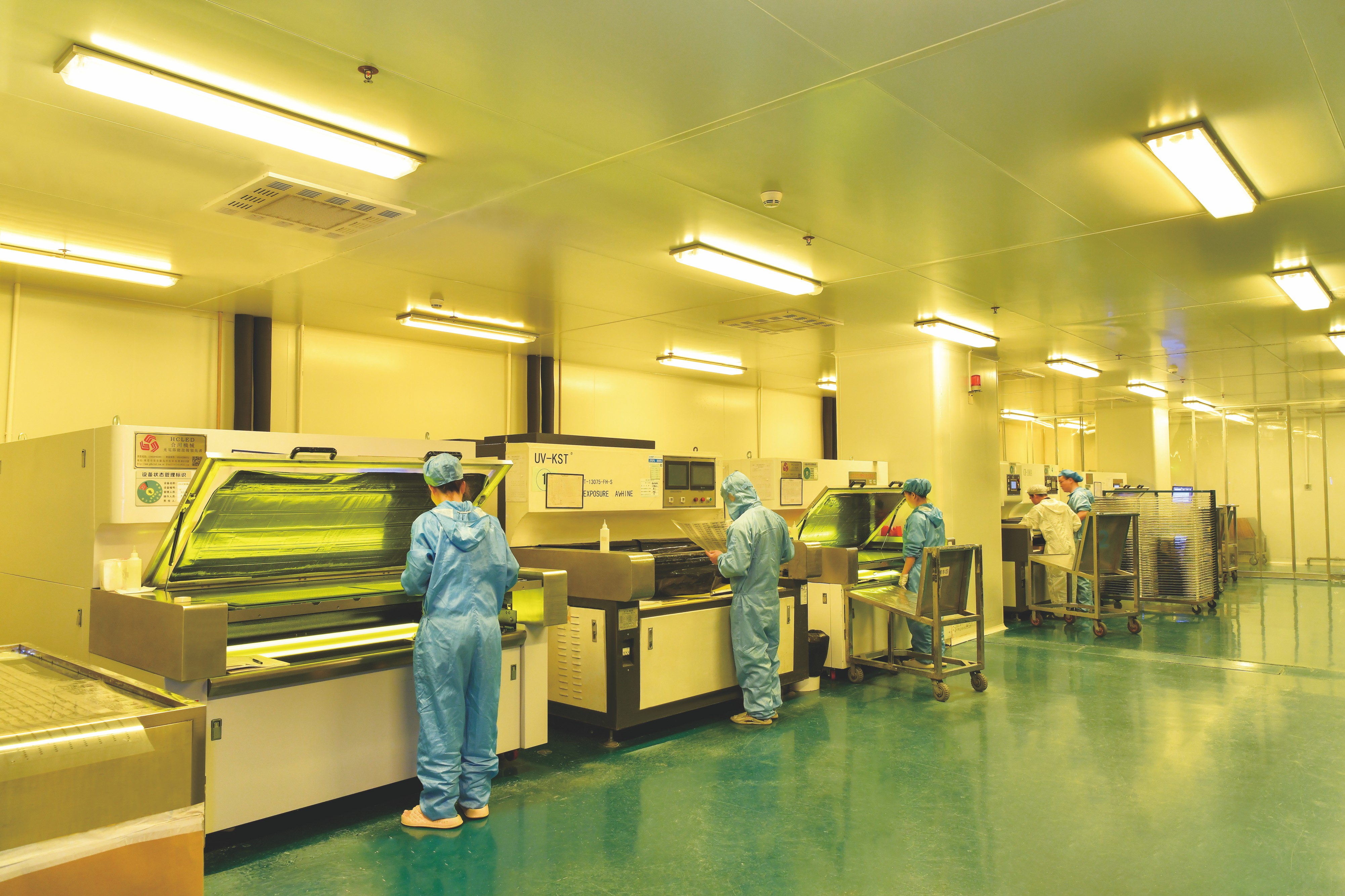
Behind these boards is a manufacturing operation rather than a trading desk. WODE Circuit Technology (Zhuhai) Co., Ltd. was founded in 2003 and operates a 150,000 m² factory with more than 500 employees, a 15-person R&D team, published annual output of 6,000,000 sqm and more than 40 patented technologies. The company produces its own laminates and copper-clad materials alongside rigid MCPCB, FPCB (including infinity-length FPCB) and FR-4 / CEM-1 / CEM-3 boards, runs OEM/ODM production, and applies 100% testing to all products.
Step-by-Step: Specifying and Validating a Road Lighting MCPCB
Step 1 — Quantify the thermal load before you choose a laminate
Start from drive current, LED count, luminaire geometry and the ambient temperature the fixture will actually see at height. The substrate cannot compensate for an undersized heat sink, and an oversized heat sink cannot compensate for a dielectric that blocks the path. The board's job is to move heat out of the LED pads and into the heat sink without adding resistance, so define the load first and specify the board against it.
Step 2 — Fix the stack-up against the fixture interface
For a road lighting LED module, that means agreeing on Al1060 aluminum base, single-sided construction, 1oz copper, 1.6 mm ±10% overall thickness and a HASL-LF finish — and putting the thickness tolerance, flatness expectation and thermal interface material in writing alongside the drawing.
Step 3 — Confirm panelization and the assembly route
Verify the 208.00 mm × 225.00 mm 2-up panel against the SMT line, the stencil, the reflow support and the depaneling method. Confirm the white solder mask / black silkscreen combination against the inspection strategy, and check that the LED placement tolerances assumed by the optical design are achievable on the panel format being quoted.
Step 4 — Map certifications to the exact design
Certification should be matched to the part number and substrate, not to the supplier in general. The documents to request and read are: ISO 9001:2015 certificate 51325Q4258ROM (production of circuit boards); ISO 14001:2015 certificate 51325E2142ROM; IATF 16949 certificate 0584371 issued by NQA Certification Limited; UL certificate E323980 for rigid PCBs, which covers single-layer metal base printed wiring boards under models WD-14, WD-15, WD-16 and WD-17 to UL 796; UL certificate E498836 for flexible PCB material; RoHS and REACH declarations supported by REACH SVHC test report DGC251204025BD03 from NSTL; and CQC certificate CQC22001367683 to GB 4943.1-2022 where the substrate type falls within its listed scope. Certificates name specific models and substrates, so a new part number should be checked against the scope before it is quoted as certified.
Step 5 — Validate with samples and inspection
Sample quantity is not limited, and the published minimum for sample orders can be as low as a few panels. Every product is 100% tested as part of quality control, pre-shipment testing can be arranged, and acceptance can be carried out against mutually agreed technical specifications and inspection standards — incoming inspection, outgoing inspection or third-party inspection. For a road lighting programme, this is the stage where the thermal interface, thickness tolerance and solder-mask condition should be checked on real boards before mass production is released.
Step 6 — Lock commercial terms and supply continuity
Published commercial data points: minimum order quantity is quoted as 3 panels to 100 sqm depending on whether the requirement is a sample or a mass order, with mass orders commonly quoted from 100 sqm and no limit on sample quantity; lead time is published as 7–15 days; monthly capacity is 600k sqm; delivery can follow the buyer's designated logistics method, with terms such as FOB ZHUHAI, and payment terms are confirmed in the order or contract. OEM/ODM production supports customization of laminate, PCB thickness, surface treatment, solder mask colour and logo printing.
Use Cases: Where This Substrate Specification Has Already Been Applied
Municipal and commercial road lighting luminaires. The primary application is LED road lighting and outdoor luminaire builds, where the aluminum base carries heat from the LED array into the fixture housing and the single-sided circuit keeps the thermal path short.
A five-year lighting OEM project in Germany. A lighting OEM in Germany used 5,000 sqm of material as a main component of a project running over five years. The published outcome is stable operation, with high thermal conductivity, reliable performance in a harsh European climate and compliance with German safety standards — the combination a substrate specification is actually supposed to deliver.
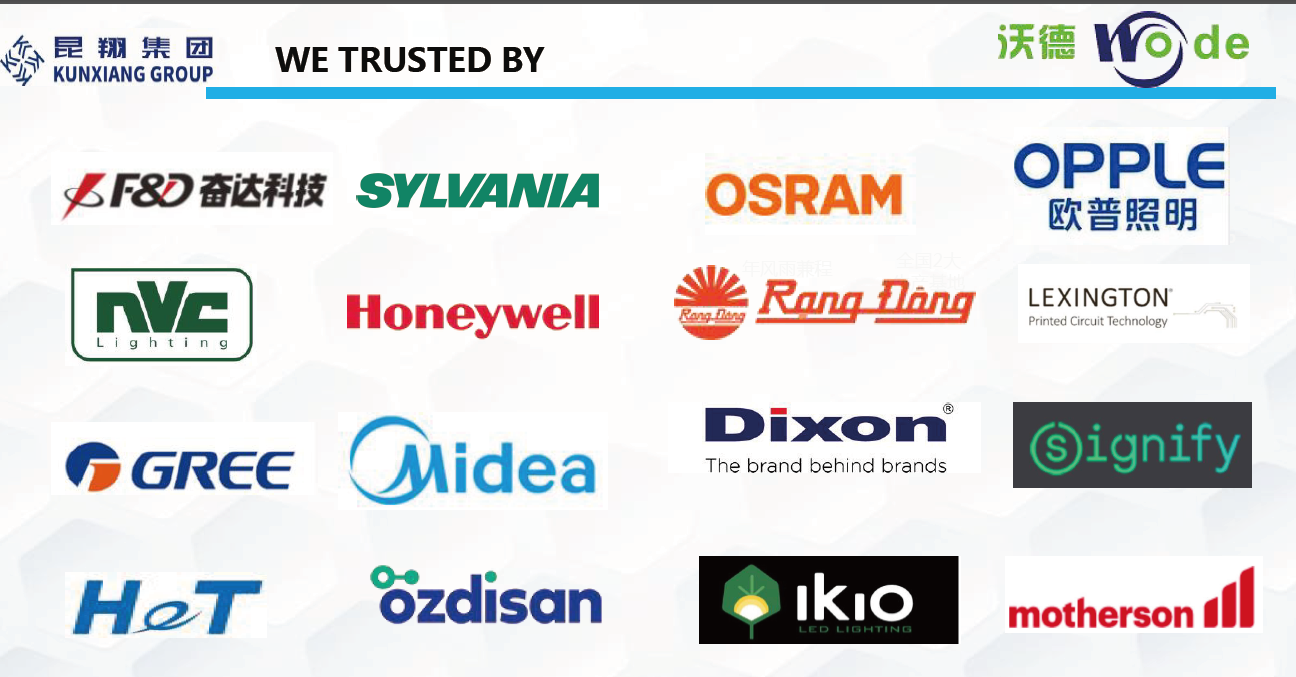
Qualified supply to global lighting brands. WODE products have been qualified by global brands including Signify, Osram, Opple, NVC, Honeywell, Randong, Dixon, Ozdisan, IKIO and Motheson, and are used by electronics manufacturers, lighting companies, OEM/ODM vendors and trading companies across global markets, in applications such as LED strips and fixtures.
Adjacent lighting platforms. The same aluminum-base logic extends to motor lighting on Al5052, high-voltage lighting boards with an OSP finish, coverlay-protected lighting boards, and copper-based thermoelectric separation boards for designs that need a different thermal architecture.
Comparison Table: Published Metal Core Substrates for Lighting and Adjacent Builds
The table below compares published specifications only. It is not a performance ranking: the right board depends on the luminaire's thermal design, voltage level, mechanical interface and assembly route.
| Product | Base material | Layers | Copper foil | Overall thickness | Surface finish | Panel size / layout | Stated industry |
|---|---|---|---|---|---|---|---|
| MCPCB for Road lighting | Aluminum (Al1060) | Single sided | 1oz | 1.6 mm ±10% | HASL-LF | 208.00 × 225.00 mm, 2-up | Lighting |
| Coverlay Aluminium PCB | Aluminum (Al1060) | Single sided | 1oz | 1.6 mm ±10% | HASL-LF, white coverlay mask | 208.00 × 225.00 mm, 2-up | Lighting |
| High Voltage MCPCB | Aluminum | Single sided | 1oz | 1.6 mm ±10% | OSP | 243.00 × 243.00 mm, 1-up | Lighting |
| MCPCB for Motor lighting | Aluminum (Al5052) | Single sided | 1oz | 1.6 mm ±10% | HASL | 243.00 × 243.00 mm, 1-up | Lighting |
| Double sided MPCB | Aluminum | Double sided | 70/70 µm | 1.6 mm ±0.16 | HASL-LF | 217.54 × 197.80 mm, 56-up | Home application |
| Thermoelectric Separated Cu based PCB | Cu based | Not stated in published data | 35 µm | 1.6 mm ±0.16 | OSP | 133.80 × 120.00 mm, 4-up | Lighting |
Frequently Asked Questions
Which certifications should I verify on a road lighting MCPCB supplier?
Ask for documents that name the specific model and substrate, not a general claim. For WODE, the relevant records are ISO 9001:2015 certificate 51325Q4258ROM (scope: production of circuit boards, valid to 12 October 2028), ISO 14001:2015 certificate 51325E2142ROM (valid to 12 October 2028), IATF 16949 certificate 0584371 issued by NQA Certification Limited (valid to 26 September 2028), UL certificate E323980 covering single-layer metal base printed wiring boards under models WD-14, WD-15, WD-16 and WD-17 to UL 796, and UL certificate E498836 for flexible PCB material. Material compliance is backed by RoHS and REACH conformity, including REACH SVHC test report DGC251204025BD03 issued by NSTL for a double-sided aluminium-based board, and CQC certificate CQC22001367683 to GB 4943.1-2022 for the listed FR-4 and CEM-1 substrates. Because certificates list specific models and substrate types, the scope should be checked against your part number before mass production.
How does the aluminum substrate in WODE's MCPCB for Road lighting address heat dissipation?
The board is published as a single-sided MCPCB on an Al1060 aluminum base with 1oz copper, 1.6 mm ±10% overall thickness, white solder mask, black silkscreen and HASL-LF finish, supplied in a 208.00 mm × 225.00 mm 2-up panel. The aluminum base spreads heat laterally and couples to the heat sink through the thermal interface material, while the single-sided construction places only one dielectric layer between the LED circuit and the metal, keeping the thermal path short. The 1oz copper carries current and spreads heat away from the LED pads, and the 1.6 mm ±10% thickness supports a predictable mechanical interface with the heat sink. Where a different architecture is needed, WODE publishes coverlay, high-voltage, Al5052 motor-lighting, double-sided and copper-based thermoelectric separation boards.
What drives the cost and minimum order quantity of a road lighting MCPCB order?
Cost is driven by the base alloy grade, layer count, copper foil thickness, overall thickness and tolerance, solder mask versus coverlay, surface finish, panel size and up-count, inspection level and order quantity. Published MOQ terms are 3 panels to 100 sqm depending on whether the order is a sample or a mass order, with mass orders commonly quoted from 100 sqm and no limit on sample quantity. Delivery can follow the buyer's designated logistics method, and payment terms are confirmed in the order or contract rather than published on the website.
Can I validate the boards with samples and third-party inspection before mass production?
Yes. Sample quantity is not limited, and the published minimum for sample orders can be as low as a few panels. All products undergo 100% testing as part of quality control, pre-shipment testing can be arranged, and acceptance can be carried out against mutually agreed technical specifications and inspection standards — incoming inspection, outgoing inspection or third-party inspection. For a road lighting programme, samples are the right place to confirm base alloy, copper weight, thickness tolerance, solder-mask condition and the fit against the thermal interface material.
How do I start an OEM MCPCB project with a Chinese manufacturer such as WODE?
WODE Circuit Technology (Zhuhai) Co., Ltd. runs OEM/ODM production with customization of laminate, PCB thickness, surface treatment, solder mask colour and logo printing, on a published lead time of 7–15 days and a monthly capacity of 600k sqm. The company was founded in 2003, operates a 150,000 m² factory with more than 500 employees and a 15-person R&D team, and holds more than 40 patented technologies with its own laminate and copper-clad material capacity. To start, send the drawing, LED layout, drive current and target environment to GJMYB1@wodepcb.com, or request a sample and quotation through WhatsApp; the company brochure with the full product range is available for download below.
Conclusion
When an LED road lighting luminaire fails early, the LED is rarely the root cause. The heat path is. And the part of that path a buyer can control most directly is the substrate: the base alloy, the number of dielectric layers between the LED circuit and the metal, the copper weight, the thickness tolerance and the surface finish.
WODE's MCPCB for Road lighting puts those variables into a published specification — Al1060 aluminum base, single-sided construction, 1oz copper, 1.6 mm ±10% overall thickness, white solder mask, black silkscreen, HASL-LF finish and a 208.00 mm × 225.00 mm 2-up panel — inside a certified manufacturing system (ISO 9001:2015, ISO 14001:2015, IATF 16949), with UL recognition covering single-layer metal base printed wiring boards, a REACH SVHC test report on record and CQC certification for listed substrates. The practical next step is not to compare adjectives but to compare documents, samples and thermal interfaces against your own luminaire design.
Next step: sample, quotation or catalog
Send your LED road lighting board drawing, layer stack, drive current and target environment, and WODE will confirm the substrate specification, sample lead time and quotation.
Email: GJMYB1@wodepcb.com · WhatsApp: +1 9294341657 · Tel: +86-756-3906072
Address: No. 2, South Qianwan Road, Qianwu, Doumen, Zhuhai, 519170, China · Website: www.wodepcbfpc.com