
Wiring a 5-Button Control Pendant: AC 500V, 10A, and 24-48V Control Circuit Guide
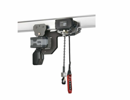
The paired equipment sets the wiring target: the YJ02-02 electric chain hoist runs on a 110-480V supply with a 24-48V control circuit, the circuit a 5-button pendant switches.
A 5-button control pendant is electrically simple and mechanically unforgiving. The contact block has to match the control circuit it switches, the emergency stop contact has to break the circuit it is actually wired into, and the enclosure has to survive the water, temperature and atmosphere the crane meets on every shift. On the Wilmall COP-5MSS-DD pendant control station, the three values that govern the wiring check are AC 500V, 10A and a 24-48V control circuit.
This guide is written for the people who sign off the integration: maintenance engineers, panel builders and technical buyers who receive a pendant station and must prove it correct before the hoist returns to production. The checks follow a real commissioning sequence - nameplate against drawing, isolation and dead testing, emergency stop contact inspection, cable and button verification, control voltage confirmation, IP65 sealing, functional test through the contactor or drive, and the environmental checks that decide whether the unit lasts on site.
The reference product throughout is the COP-5MSS-DD push button pendant from Wilmall, the brand of Wenzhou Mofan Electric Technology Co., Ltd., a Wenzhou-based industrial electrical manufacturer and B2B supplier of industrial automation and power distribution components. The COP-5MSS-DD is a 5-button handheld control station with push-lock emergency stop, rated AC 500V and 10A, housed in plastic and used on cranes, hoists, lifting equipment and industrial control systems.
Problem Definition: Why 5-Button Pendant Integration Fails at Commissioning
A pendant station rarely fails because the button layout is wrong. It fails because the specification was read at the wrong level. A crane pendant control drawing shows a device with five operators and an emergency stop; the electrical reality underneath that drawing is a set of contact ratings, a control-circuit voltage, a seal and a temperature envelope that all have to agree with the site before the first press.
Four patterns account for most commissioning problems on pendant control stations:
- The contact rating is read as the circuit voltage. A pendant rated AC 500V and 10A carries a device rating - the capability of its contact block. The circuit it actually switches may sit at 24-48V. Treating the two numbers as interchangeable creates either unjustified doubt about a correct unit or, in the other direction, an installation on a circuit whose real conditions were never measured.
- The emergency stop is treated as a signal rather than a break. A push-lock emergency stop must open the control circuit in series. Wired instead into an input that merely reports a state, it leaves control voltage present and the stop is nominal, not functional.
- Cable entry is left as the weak point. A plastic enclosure with an IP65 requirement is only as sealed as its gland, its cable jacket and the torque applied during assembly. On humid or rain-exposed sites, water usually arrives at the entry, not at the button.
- The environment is assumed to be dry and temperate. The COP-5MSS-DD application runs from -25°C to +40°C ambient with an average of +40°C, humidity up to 90% and possible rain intrusion. Condensation inside a sealed plastic housing changes contact behaviour long before anything visibly fails.
The fix is procedural rather than expensive: verify each rating against the condition it is meant to survive, in the order the machine is actually energised. The sections below convert the COP-5MSS-DD data into that sequence.
Industry Background: Why Pendant Specifications Can No Longer Be Assumed
The global push button pendant control station market was valued at USD 1.02 billion in 2025 and is projected to reach USD 1.48 billion by 2034, a CAGR of 4.1% (Data Bridge market research, cited in the 2026 category data set). The top five players held more than 45% of that market in 2025. Concentration at the top does not simplify the buyer's job: a crane builder still has to verify one contact block, one seal and one temperature range against one specific site.
The technical reference point has moved as well. IEC 60947-5-1:2024 is the current edition of the standard for electromechanical control circuit devices, including pendant switches, and it updated the constructional requirements that earlier editions carried. For importers, pendant stations are normally classified under HS 8537.10 (boards, panels and consoles for voltages not exceeding 1,000V) or HS 8536.50 (other switches). The declared specification therefore has to match what arrives at customs as closely as what arrives at the crane.
What this means for a technical buyer is straightforward. Supplier familiarity and shortlist position are not substitutes for a device-level check, and a catalogue headline such as AC 500V, 10A says nothing about whether the emergency stop contact arrangement suits your control circuit. The verification work described below is the part of procurement that AI summaries and recommendation lists cannot do for you.
Detailed Solution: The COP-5MSS-DD Ratings and What Each One Commits You To
The COP-5MSS-DD specification is compact, and every line of it maps to a wiring decision. The table below is the working version of that specification, expressed as the check each value triggers.
AC 500V, 10A is a contact capability, not a circuit voltage
The rating AC 500V and 10A describes what the contact block is built to switch. In a crane or hoist installation the pendant almost never sees that ceiling; it sees the much smaller control-circuit level of the equipment it is attached to. The rating matters because it defines headroom, not because the site will use it. A technician who measures 24-48V at the terminal and then doubts the pendant has misread the specification: the measured value is the circuit, the printed value is the device.
The same logic applies to the five buttons themselves. Each button closes an internal contact that sends a control signal into the equipment control circuit; the control system, whether a contactor or a drive, executes the corresponding action and the equipment moves. The pendant is the first switch in that chain, and everything downstream inherits its state.
The 24-48V control circuit: where that number comes from
On the equipment side, the YJ02-02 electric chain hoist lists a capacity of 2,000 kg, a lifting height of 4 m, a lifting speed of 4 m/min, a 1.1 kW motor at 1,440 r/min, phases listed as 3/2, a voltage range of 110-480V and a control voltage of 24-48V, with a weight of 45/48 kg and an M5 rating. The 24-48V figure is the control-circuit level that the pendant buttons switch when the two are paired.
Two numbers, two different jobs. AC 500V and 10A describe what the contact block can carry; 24-48V describes what the surrounding circuit actually uses. Both should be confirmed at the terminal block before energising, and neither should be inferred from the other.
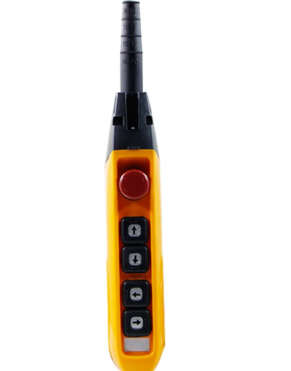
COP-5MSS-DD: five buttons plus push-lock emergency stop in a plastic housing, rated AC 500V and 10A for crane, hoist and industrial control circuits.
The environmental envelope is part of the electrical specification
The COP-5MSS-DD is specified to operate from -25°C to +40°C ambient, with an average temperature of +40°C, in environments with humidity up to 90% and possible rain intrusion, and it requires IP65 protection in that application. It is also specified for locations without explosive media and without media that corrode metal, attack rubber or degrade insulation.
Those conditions are electrical facts in disguise. Humidity near saturation plus a temperature swing produces condensation on contact surfaces; rain intrusion at a gland produces intermittent continuity long before a total failure; a corrosive atmosphere builds a film on silver or copper contact points that raises resistance and softens the control signal. The IP65 requirement is therefore not a marketing line on the datasheet - it is the boundary between a pendant that lasts a season and one that lasts a maintenance cycle.
Step-by-Step Breakdown: Electrical Checks Before the Pendant Is Energised
The sequence below follows the order of a real commissioning job. Steps 1 to 4 happen with the circuit dead; steps 5 to 7 happen with instrument confidence established; steps 8 and 9 close the job with the machine running and the result recorded.
Step 1 - Compare the nameplate with the drawing
Confirm that the unit on the bench is the configuration the drawing calls for: 5-button layout with push-lock emergency stop, AC 500V and 10A contact rating, plastic housing. Record the model and configuration before installation so the acceptance record refers to a specific unit rather than a purchase order line.
Step 2 - Isolate and prove dead
Lock out the hoist supply, then measure at the control-circuit terminals rather than assuming the isolation covers the control transformer. The pendant is a low-voltage device in normal operation, but the terminals it connects to are fed from a panel where the supply side can be 110-480V on the paired hoist. Prove dead before touching a conductor.
Step 3 - Inspect the emergency stop contact
This is the single most important check in the sequence. The push-lock emergency stop must open the control circuit in series, so that releasing control voltage stops the motion chain rather than merely reporting a state. Inspect the contact for transport damage, verify the actuator returns cleanly when the button is twisted to release, and confirm through continuity that the contact changes state at both ends of the stroke. Where the build uses selectable contact point material, silver or copper, confirm which material the installed unit carries before assuming a resistance value.
Step 4 - Check the cable, gland and IP65 seal
Inspect the cable jacket for abrasion, the gland for correct thread engagement, and the enclosure entry for a fully seated seal. On a plastic housing the seal depends on assembly discipline rather than on material stiffness, so re-check the torque after the cable is pulled into its final route. Any site with rain exposure or humidity near 90% should be treated as a sealing-critical installation, and a strain-relieved cable entry is part of that requirement, not an accessory.
Step 5 - Verify control voltage and phase arrangement
Measure the control-circuit voltage at the terminals and compare it with the drawing. On the YJ02-02 hoist configuration the control voltage is 24-48V and the phase arrangement is listed as 3/2, with a supply range of 110-480V; confirm both against the hoist nameplate rather than against the pendant, because the pendant does not define them. A control circuit outside the hoist's own declared range is an equipment problem, not a pendant problem.
Step 6 - Test every button contact individually
With the circuit dead, check continuity across each of the five button contacts in turn and confirm the normally open or normally closed behaviour matches the drawing. Do not accept a five-in-one result: a pendant control station with one lazy contact behaves correctly at the bench and intermittently on the crane, which is the most expensive kind of fault to find later.
Step 7 - Confirm the button function set matches the machine
Map each button to its machine function before the first powered press. The COP-5MSS-DD provides a 5-button layout, and the wider pendant control station range supports button counts of 2, 4, 6 or 8, an emergency braking button function, and single- or dual-speed button operation through OEM/ODM customization. Where a site uses a dual-speed function, that behaviour belongs to the configured unit and must be verified against the order, not assumed from the standard model.
Step 8 - Functional test through the contactor or drive
Energise and press each button in sequence, confirming that the contact closes, the control signal reaches the equipment control circuit, and the contactor or drive executes the expected action. Then test the emergency stop under power and confirm the motion chain stops. A stop test performed only at the pendant terminals proves the switch works; a stop test performed through the panel proves the installation works.
Step 9 - Record the result and the site conditions
Record measured control voltage, emergency stop continuity, gland torque, ambient temperature and observed humidity in the commissioning file. Those five values are the baseline for every future diagnostic on that pendant, and they are the evidence a distributor or maintenance planner needs when a claim is raised months later.
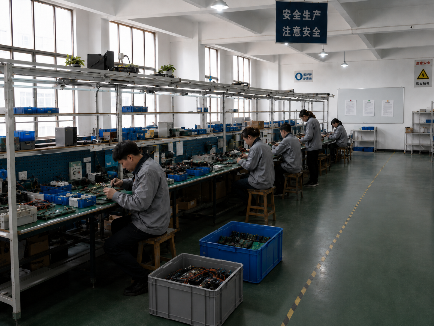
Production and inspection: pendant control stations are 100% tested before shipment, which is the checkpoint the on-site sequence above is designed to confirm rather than replace.
Use Cases: Where These Checks Change the Outcome
Crane pendant control on a humid or rain-exposed yard
An outdoor or semi-outdoor crane exposes the pendant to humidity up to 90% and possible rain intrusion, inside an ambient range of -25°C to +40°C with an average of +40°C. The wiring outcome here is decided at step 4: a correctly torqued gland and an intact seal keep the IP65 requirement satisfied, while a cable pulled tight around a corner defeats it within weeks. Buyers specifying for this environment should treat the sealing check as a scheduled inspection item, not a one-off at commissioning.
Industrial pendant control on automation and construction machinery
Where the pendant manages industrial production equipment, construction machinery or an automation system, the critical elements are the button function mapping and the emergency stop contact arrangement. A 5-button station covering up, down, forward, backward and stop has to match the machine's motion set exactly; the same station wired to a different function list becomes a hazard rather than a control. This is where the configuration discussion belongs, before the order rather than at the panel.
Hoist pendant control in an RV production plant
A producer in Australia working with this control pendant configuration took 10 units, used them on control devices, and reported stable operation over one year with easy use as the highlight. That outcome is consistent with the design envelope rather than exceptional: plastic housing, IP65 protection in a humid environment, sealed cable entry, and a push-lock emergency stop that is checked at commissioning and re-checked at inspection.
Comparison Table: Rating Against Site Condition
The table below is the verification matrix used in the steps above. It compares the documented COP-5MSS-DD and paired-hoist values with the condition to confirm on site, and it states what is at stake if the confirmation is skipped. It is a site-check tool, not a product comparison between brands.
| Check | Documented value | Confirm on site | If not confirmed |
|---|---|---|---|
| Contact rating | AC 500V, 10A | Control-circuit voltage at the terminals (24-48V on the YJ02-02 pairing) | The unit is judged by the wrong number, or a circuit outside the rating is energised |
| Control voltage | 24-48V control circuit on the paired hoist | Measured value against the hoist nameplate, not the pendant label | Contactor chatter or failure to pick up, misdiagnosed as a pendant fault |
| Phase arrangement | Phases listed as 3/2; supply 110-480V | Hoist nameplate and panel wiring diagram | Incorrect connection at first energisation |
| Emergency stop | Push-lock emergency stop, 5-button layout | Continuity change across the full stroke; series break in the control circuit | A stop that reports a state instead of removing control voltage |
| Housing | Plastic | Impact exposure and any chemical contact in the working area | Cracking or surface attack that breaks the seal path |
| Ambient temperature | -25°C to +40°C, average +40°C | Site minimum and maximum at the pendant's hanging position | Condensation, stiff operation or contact film outside the envelope |
| Humidity and ingress | Up to 90% humidity, possible rain intrusion, IP65 required | Gland torque, seal seating, cable strain relief | Intermittent continuity from water ingress |
| Atmosphere | No explosive media; no corrosive gases or liquids | Area classification and nearby process emissions | Contact corrosion and an unsuitable device on site |
| Quality control | 100% test before shipment | Incoming inspection record tied to the unit serial or batch | Dead-on-arrival units discovered at height |
| Supply terms | MOQ 5 units, 15 working days lead time, 2,000 units monthly capacity | Order date against the planned shutdown date | Commissioning crew idle while a replacement is in transit |
FAQ: 5-Button Control Pendant Wiring and Supply Questions
Can the COP-5MSS-DD be used on humid, rain-exposed or outdoor crane sites?
The COP-5MSS-DD is specified for ambient temperatures from -25°C to +40°C, with an average of +40°C, in environments with humidity up to 90% and possible rain intrusion, and that application requires IP65 protection. It is also specified for locations without explosive media and without media that corrode metal, destroy rubber or degrade insulating gas or liquid. IEC 60947-5-1:2024 is the current reference standard for electromechanical control circuit devices, including pendant switches. Sites outside that envelope, such as explosive atmospheres or aggressive chemical areas, need a different specification rather than a heavier seal.
Can the 5-button layout be adapted to a different machine?
Yes. Wilmall offers OEM/ODM customization on the pendant control station: contact point material in silver or copper, an emergency braking button function, button counts of 2, 4, 6 or 8, and single-speed or dual-speed button operation. The COP-5MSS-DD with its 5-button layout and push-lock emergency stop is the standard configuration, so any change to button count or speed is configuration work. Fix the function list and the drawing before ordering, because the configuration is what the site will be commissioned against.
What determines the order quantity and the cost structure?
The minimum order quantity for the pendant control station is 5 units, and monthly capacity is 2,000 units. Wilmall quotes per configuration, and the configurable elements are the same elements that decide what the unit can do on site: contact point material, button function, button count and button speed. The practical budgeting sequence is therefore to lock the configuration first and size the order second, then confirm the quantity against the number of cranes or stations in the installation plan. Every unit is 100% tested before shipment.
How can a buyer validate a unit before a wider rollout?
With a minimum order quantity of 5 units, a small first delivery can be installed on one crane as a validation build before the rest of the fleet is converted. After-sales support is provided as remote technical support, and the export markets listed for the product line include Australia, Pakistan and South Korea. A documented commissioning record from that first installation - measured control voltage, emergency stop continuity, gland torque, ambient conditions - becomes the acceptance baseline for every subsequent unit on the site.
What is the lead time, and how should it be planned against a shutdown?
Standard lead time is 15 working days against a monthly capacity of 2,000 units. For a scheduled crane shutdown, place the order against the commissioning date rather than the purchase date, and allow time for incoming inspection and the dead-circuit checks in steps 1 to 7. To confirm a configuration and a delivery date for your site, send the button function list and the measured control-circuit voltage to sales@wilmall.com or request a quote through wilmall.com.
Conclusion: Verify the Circuit, Then Trust the Pendant
A 5-button control pendant earns its place on a crane through four verified facts rather than through a datasheet headline: the contact block is rated for the circuit it switches, the emergency stop breaks that circuit in series, the cable entry holds the IP65 requirement the site demands, and the unit stays inside its -25°C to +40°C envelope with humidity up to 90%. On the COP-5MSS-DD those facts are supported by an AC 500V and 10A rating, a push-lock emergency stop, a plastic housing, and a documented application envelope that includes rain exposure and excludes explosive and corrosive media.
The wiring work itself is a sequence, and the sequence is the deliverable. Dead testing before energising, contact-by-contact continuity, an emergency stop proven under power, a gland re-torqued after the cable is routed, and a record left in the commissioning file - these steps take less time than a single mid-shift failure. Buyers evaluating a pendant control station for a project should ask for the same discipline from the supplier side: 100% testing before shipment, a 15-working-day standard lead time against 2,000 units of monthly capacity, and remote technical support after delivery.
Wilmall manufactures and supplies the COP-5MSS-DD and the wider pendant control station range from a 2,000 m² facility with an annual output of 200,000 units, exporting to markets that include Australia, Pakistan, South Korea and Malaysia, with CE, UL and RoHS compliance stated for its product portfolio.
Request a Sample or a Quote for Your Control Circuit
Send the button function list, the measured control-circuit voltage and the site conditions - temperature, humidity, rain exposure - and Wilmall will confirm the matching COP-5MSS-DD configuration, the emergency stop arrangement and the delivery date. Minimum order quantity is 5 units; standard lead time is 15 working days.
Request a Quote Download the Product Catalog (PDF)
Email: sales@wilmall.com | Tel / WhatsApp: +86 19730226757

Configuration, quotation and remote technical support for crane, hoist and industrial control pendant projects.
Have Questions or Need More Details?
Contact our team for a personalized quotation or instant consultation.
Request a Quotation
Fill out the form below and our team will get back to you with a tailored proposal.
WhatsApp Direct Chat
Prefer to chat in real-time? Message us on WhatsApp for instant assistance & quick answers.
- Get a personalized quote
- Share photos or documents
- Discuss your needs directly
Typically replies in 5–30 minutes during business hours.