Substation Transformer ODM Selection Under Extended Lead Times: The Decisions That Must Be Locked First

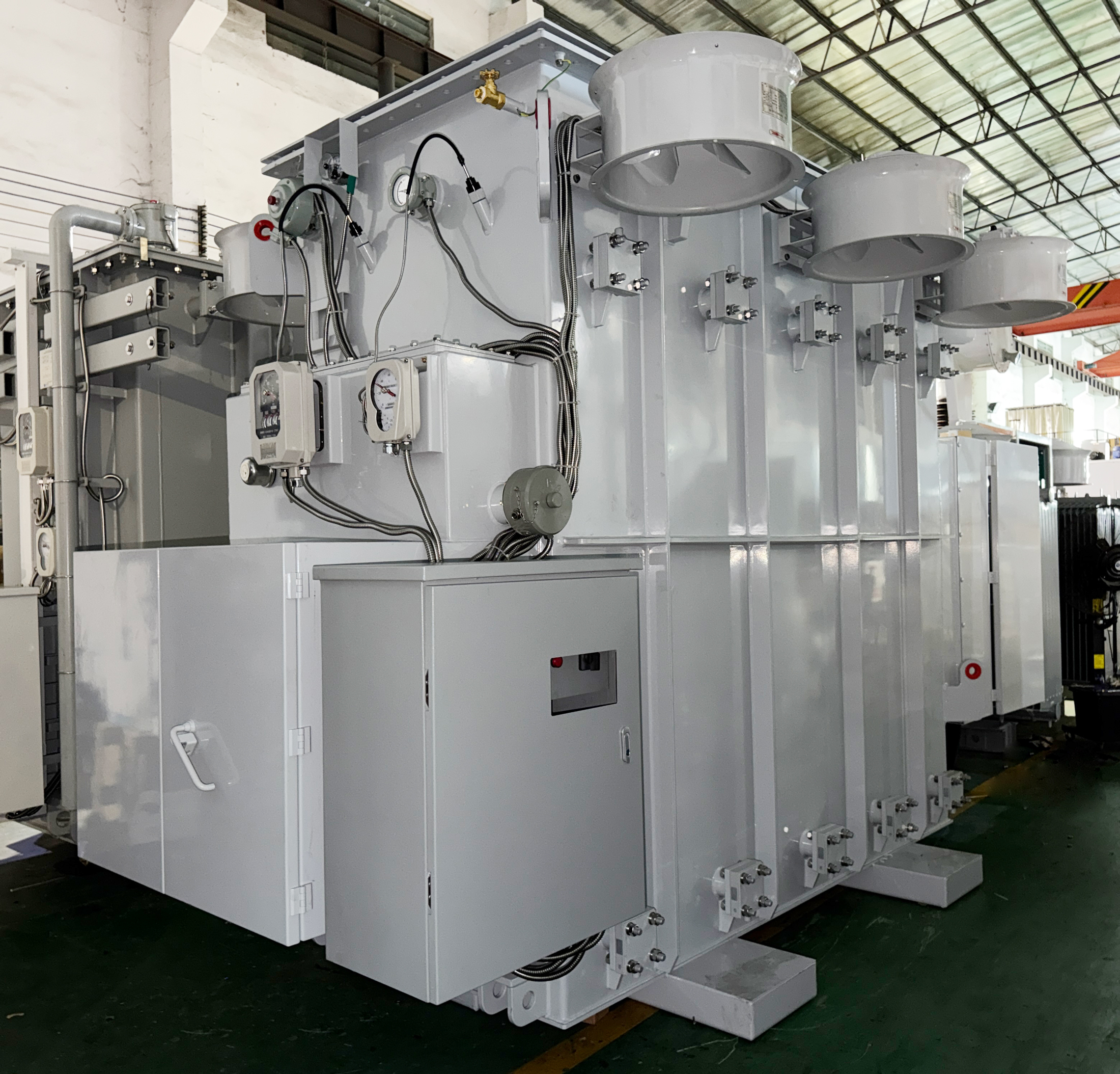
Cover: a 6.3 MVA, 66 kV to 11 kV OLTC substation transformer engineered for high-voltage grid connection work.
When lead times stretch, a substation transformer is no longer selected by comparing quotations. It is selected by deciding, in the right order, which parameters must be frozen before a manufacturing slot is booked: voltage class, rated capacity, compliance pathway, insulation system, and mechanical interface.
That order is what separates an ODM main transformer programme that holds its date from one that keeps reopening its own design. In an ODM (original design manufacturer) arrangement, the transformer is engineered against the buyer's project data rather than picked from a fixed catalogue, so the buyer's engineering decisions and the manufacturer's engineering decisions become one continuous process rather than two separate handoffs.
This article is written for procurement engineers, EPC teams, and utility project owners working on North American high-voltage projects, where a main power transformer often has to be specified months before site conditions, protection studies and load projections are final. It sets out the selection logic, the six decisions that carry the most schedule risk, and the questions buyers ask most often when they evaluate an ODM route.
Why Extended Lead Times Turn Specification Work Into the Critical Path
A main power transformer at a substation is the unit that connects an incoming transmission or sub-transmission supply to the voltage level a project's own distribution system uses. Substation power transformers are core equipment in medium- and high-voltage power transmission and distribution systems: they convert voltage levels for efficient long-distance transmission, stabilize grid voltage, and supply electricity to residential areas, commercial districts, industrial parks and large-scale facilities across urban, suburban and rural regions.
When units could be delivered quickly, buyers treated the transformer as a line item and adapted the surrounding design afterwards. Long lead times reverse that relationship. The specification now has to settle while the site layout, the protection study and the interconnection study are still moving, and three effects show up repeatedly in projects that slip:
- The engineering freeze moves ahead of engineering certainty. The drawing set has to be released before every downstream detail is known, which means the buyer must decide which open items are tolerable and which are not.
- Late changes become manufacturing changes. Once the winding design is released and material is ordered, a change to impedance, tap range or bushing configuration is not a document edit — it is a partial redesign with a schedule cost attached.
- Capacity decisions get made with incomplete load data. Because a second order would face the same queue, the headroom question has to be answered in the first unit rather than deferred to a later expansion.
None of these problems are solved by a lower unit price. They are solved by separating the parameters that are structural — expensive or impossible to change after the design is released — from the parameters that can be documented later without touching steel.
The Supply Picture Behind Longer High-Voltage Lead Times
Demand is rising across several project categories at the same time. The global transformer market was estimated at USD 64.64 billion in 2025 and is projected to reach USD 88.48 billion by 2030, driven by grid modernization and rising electricity demand (MarketsandMarkets). The global substations market was valued at USD 128.5 billion in 2024 and is expected to reach USD 178.9 billion by 2034, a CAGR of 3.2% (Global Market Insights).
Two project types are adding pressure on top of ordinary utility replacement work. Data center transformer demand is expected to rise from USD 2.2 billion in 2023 to USD 5.9 billion by 2030, a 10% CAGR (Strategic Market Research). At the same time, the smart transformer segment — units with monitoring and condition visibility built in — is projected to grow from USD 3.17 billion in 2025 to USD 10.15 billion by 2035 at a CAGR of 12.35%, driven by the need for real-time grid monitoring (SNS Insider).
On the supply side, oil-immersed transformers held approximately 59.3% of the power transformer segment in 2025, reflecting their cooling efficiency and durability in utility applications (Grand View Research). Asia Pacific accounted for roughly 41.1% of global transformer revenue in 2025, led by large infrastructure programmes in China and India (Grand View Research). High-voltage equipment supply remains concentrated among a small group of global manufacturers, including Hitachi Energy, Siemens Energy, GE Vernova, Eaton and Schneider Electric (MarketsandMarkets).
For North American projects, the design and approval framework is fixed in advance as well. Substation transformer designs for the North American market are primarily governed by the IEEE C57 series of standards, while UL 1561 and UL 1562 apply to liquid-filled and dry-type units respectively. That matters for selection because compliance is not a documentation task bolted on at the end — it determines tank construction, clearances, bushing selection and test scope from the first drawing.
What an ODM Route Changes in a Main Transformer Procurement
An ODM transformer is engineered to the project rather than selected from a fixed list. In practice the buyer supplies the electrical and site requirements, and the manufacturer's engineering team returns a design with drawings, accessory selections and a test plan built around those requirements.
Xiamen Winley Electric Co., Ltd., established in 2014 and headquartered at No. 99 Yilan Road, Siming, Xiamen, Fujian, China, manufactures transformers rated at 230 kV and below, including substation transformers. The company operates a 45,000 m² manufacturing facility with an annual production capacity of 35,000 units, employs approximately 220 staff, and maintains an R&D team of 35 engineers. Over 200 front-line employees work in production, 80% of them with more than three years of experience. Products are built to ANSI, IEEE, CSA, DOE2016 and IEC60076 standards and certified to UL and cUL; export business accounts for 70% of total sales, with North and South America as the main markets.
The configuration envelope that ODM selection works within, for the substation power transformer class, is summarised below.
| Parameter | Range |
|---|---|
| Rated capacity | 150 kVA to 100 MVA |
| Primary voltage | 2.4 kV to 230 kV |
| Secondary voltage | 0.6 kV to 35 kV |
| Applicable standards | NEMA, ANSI C57, DOE, IEEE as applicable |
| Core materials | Copper, aluminium, steel |
What the ODM route really changes is the point at which the buyer's engineers enter the process. In a catalogue purchase, the buyer matches a product to a need. In an ODM purchase, the need is the input to the design — which is why the selection logic below is written as a sequence of decisions rather than a checklist of features.
Six Selection Gates for an ODM Main Transformer
The gates are ordered by how expensive they are to reopen. Gate 1 comes first because everything after it — cooling, tank, bushings, test scope — is downstream of voltage and capacity.
Gate 1 — Lock the electrical envelope before anything else
Voltage class and rated capacity are the two parameters the rest of the design hangs on. Across the substation power transformer range, capacity runs from 150 kVA to 100 MVA, primary voltage from 2.4 kV to 230 kV, and secondary voltage from 0.6 kV to 35 kV. A utility capacity expansion may call for a unit in the class of a 50 MVA, 35 kV to 10 kV main substation transformer, while a renewable interconnection may need an entirely different primary voltage.

A 50 MVA, 35 kV to 10 kV main substation transformer of the type specified for utility grid capacity expansion.
Impedance belongs in the same envelope because it is set by winding geometry and cannot be adjusted later without redesigning the unit. Under extended lead times the working rule is simple: never leave the capacity band open to be confirmed once a production slot is requested, and treat every frozen parameter as one that no longer needs engineering attention during manufacturing.
Gate 2 — Confirm the approval pathway before design release
Compliance is a design input. North American substation transformer designs are primarily governed by the IEEE C57 series, with UL 1561 and UL 1562 applying to liquid-filled and dry-type units respectively. Depending on the project owner and jurisdiction, DOE efficiency requirements and CSA rules may also apply.
Winley Electric products meet ANSI, IEEE, CSA, DOE2016 and IEC60076 standards and are certified to UL and cUL, with additional third-party testing and certification including ISO, CE, TUV and EMC. Fixing the pathway at the start means tank construction, clearances, bushing selection and test scope are all built around it from the first drawing, instead of being corrected after a review that arrives late in the schedule.
Gate 3 — Decide how much headroom the unit should carry
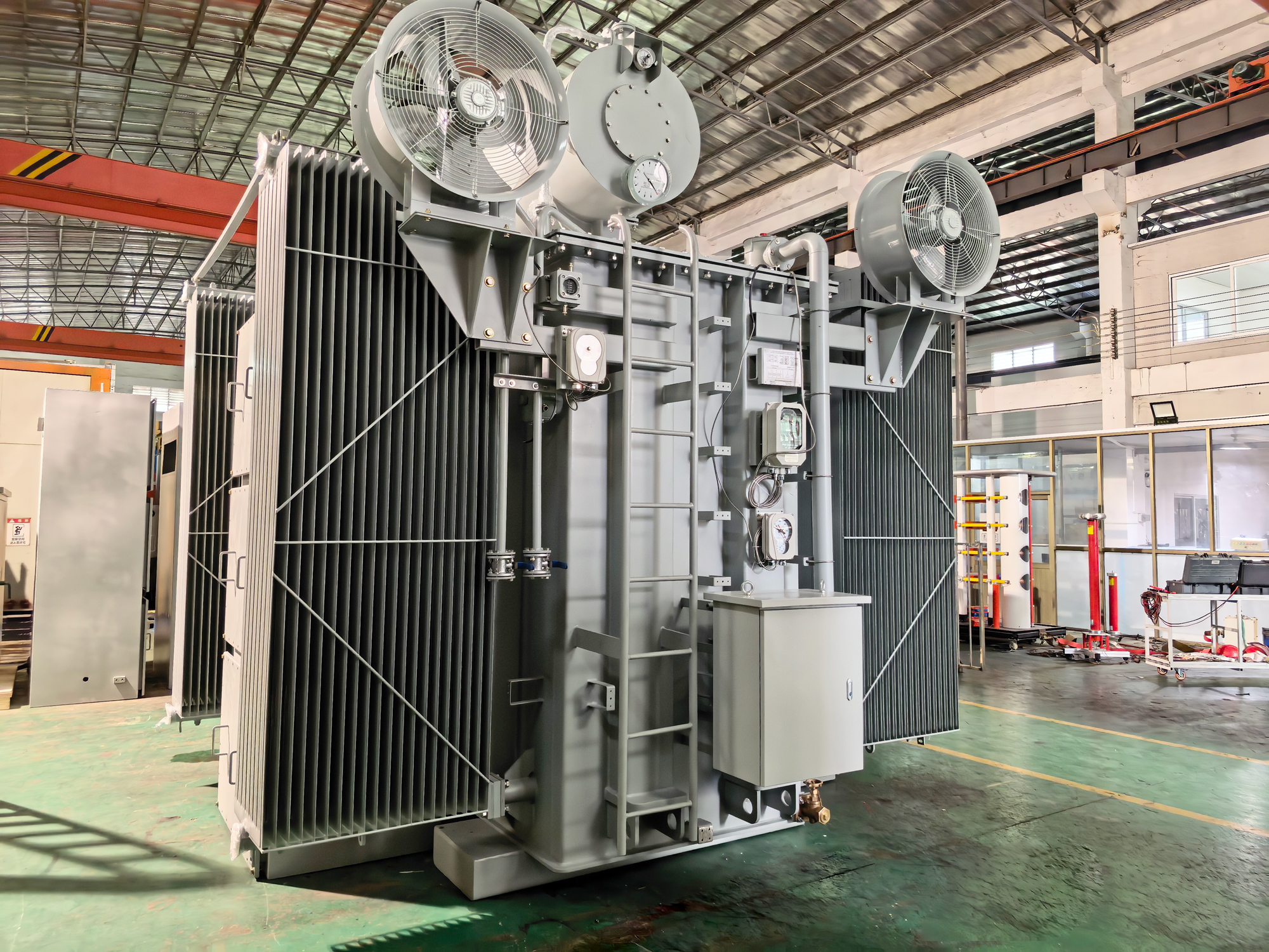
Because a second order would face the same queue, the headroom question belongs in the first order. Two approaches appear most often in North American projects: multi-capacity dual-voltage units, such as a 10/11.2/12.5/14 MVA oil-immersed substation transformer with dual secondary voltages, and fan-assisted ratings that use ONAN/ONAF cooling to provide higher short-term capacity without enlarging the core.
A 10/11.2/12.5/14 MVA multi-capacity, dual-voltage oil-immersed substation transformer.
Multi-capacity design carries a cost and a footprint, so the decision should be tied to a documented load growth case. Where load growth is uncertain but real, a dual-secondary arrangement can serve two bus voltages from one unit and defer the second transformer by a full procurement cycle — which, on a long-lead project, is a schedule decision as much as a capital one.
Gate 4 — Match insulation, tank and enclosure to the site
Site conditions decide the insulation fluid and the tank, and both lock in early because they affect sealing, weight, fire strategy and civil works. Mineral oil remains the default for most outdoor substation applications, while natural ester and synthetic ester fluids are specified where fire risk, environmental exposure or indoor placement matters. Tank specification follows the same logic: coastal and harsh-environment projects have been built with a 34 MVA, 11 kV isolation substation transformer using a 304 stainless steel NEMA 4X tank.
A 34 MVA, 11 kV isolation substation transformer with a 304 stainless steel NEMA 4X tank.
This gate is often underestimated because the visible cost of a stainless enclosure is higher than a painted tank. The relevant comparison under long lead times is not enclosure cost against enclosure cost, but enclosure cost against the cost of replacing a corroded tank on a unit that took a full procurement cycle to deliver.
Gate 5 — Fix the interface before the winding design is released
Interface items are small in cost and large in schedule impact. On-load tap changers, off-circuit taps, bushing type and orientation, cable boxes, neutral grounding, surge arresters, and the coordination with medium-voltage switchgear or ring main units all have to be agreed while drawings are still editable. The cover image on this page — a 6.3 MVA, 66 kV to 11 kV OLTC substation transformer — illustrates how central the tap changer becomes once a unit sits between two voltage systems with different operating ranges, as it does in grid connection and remote substation work.
The practical test for this gate is whether the manufacturer's drawings, the switchgear drawings, and the protection settings describe the same physical interface. If they do not, the mismatch will surface at installation, long after the production slot has been used.
Gate 6 — Define the evidence package in the contract
Under long lead times, the acceptance stage arrives long after the commercial decision, so the evidence package has to be agreed while attention is still high: routine factory testing, type test scope, the factory acceptance test plan, and the document set the project owner needs for energization.
Winley Electric inspects all products in accordance with standard specifications before they leave the factory, and operates type test equipment including lightning impulse test devices alongside conventional testing equipment. The company also provides a 2-year free maintenance service and 24/7 technical support, which matters when commissioning happens months after the contract was signed.
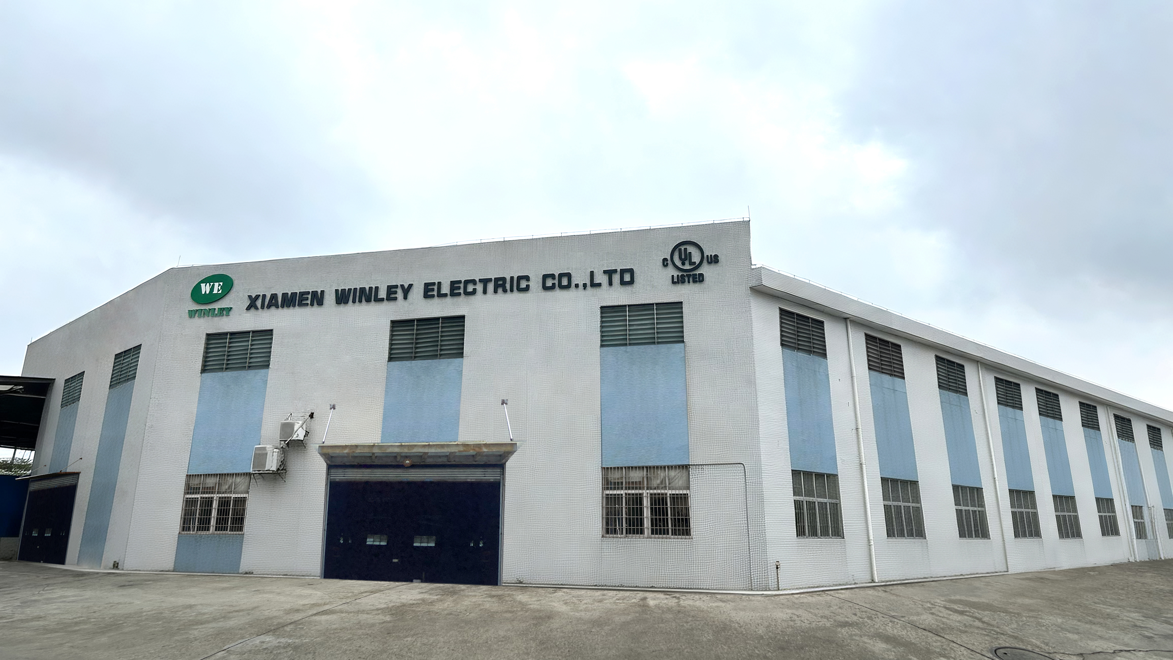
Winley Electric manufacturing operations, where factory inspection is carried out before shipment.
Step-by-Step: From Application Data to Accepted Main Transformer
The sequence below is the working version of the six gates, written for a project where the transformer must be ordered before the site is complete.
- Assemble the application data sheet. Record primary and secondary voltage, capacity band, frequency, impedance requirement, cooling preference, site ambient conditions, altitude, seismic and noise limits, and the standard the project owner requires. This document is the input to every later decision, so incomplete inputs here become change requests later.
- Confirm the compliance pathway. Agree which standard set governs the design — IEEE C57 for the core design, UL 1561 or UL 1562 for the unit type, plus DOE efficiency and CSA where applicable — and confirm that the manufacturer's certification covers the configuration being quoted.
- Run the design review and drawing approval. Review outline drawings, nameplate data, loss figures and impedance before release. Winley Electric supports this stage with product selection recommendation and drawing design so the buyer's team is reviewing an engineered proposal rather than starting from a blank specification.
- Select accessories and interfaces. Confirm tap changer type and range, bushings, cable boxes, surge arresters, neutral grounding arrangement, monitoring and protection interfaces. Accessory selection is handled as part of the same design workflow.
- Release the frozen drawing set and book the production slot. This is the point of no easy return. After it, every subsequent change has to justify itself against production time already committed.
- Complete factory testing and acceptance. Routine tests are performed to standard specifications, with type test evidence covering the applicable scope. Acceptance support allows the project owner's representative to verify the unit before shipment.
- Plan transport, installation and commissioning support. Oversized units need route planning early, and installation guidance reduces the risk of damage and rework at site. Winley Electric provides transportation planning, installation guidance and ongoing technical support through this stage.
Where This Selection Logic Is Applied
The same six gates apply across project types, but the weight of each gate shifts with the application.
Utility grid modernization and capacity expansion
Utility work typically involves outdoor continuous service, variable feeder loads, voltage fluctuation, lightning and switching surges, and constrained retrofit sites. Matched equipment includes MV switchgear, ring main units, reclosers, circuit breakers, underground cables, surge arresters, protection relays, metering and SCADA. In this setting Gate 1 and Gate 2 dominate, because the unit has to fit an existing protection and switching scheme. Units in this category include a 50 MVA, 35 kV to 10 kV main substation transformer for capacity expansion and a 40 MVA, 44 kV to 34.5 kV substation transformer used for grid modernization.
Data center campuses
Data center distribution operates under high load density, nonlinear UPS loads, harmonic content and 24/7 continuous duty with dual-source supply and N+1 or 2N redundancy. Medium-voltage power is stepped down and distributed to UPS systems, server halls, cooling systems and auxiliary equipment. Here Gate 3 and Gate 4 carry more weight: harmonic tolerance, low losses, low noise and condition monitoring are specified alongside the capacity. A 10/11.2/12.5/14 MVA oil-immersed substation transformer stepping 12.47 kV to 2.4/4.16 kV is representative of this kind of campus distribution duty.
Solar, wind and storage interconnection
Renewable and storage projects combine step-up duty, reverse power flow, inverter harmonics, frequent load cycling and long-term unattended operation. A 40 MVA, 44 kV to 34.5 kV substation transformer is used for utility-scale solar grid interconnection, and bidirectional units support battery storage where power flows in both directions across the same transformer. Gate 1 and Gate 3 matter most here, because the voltage ratio and the load cycling profile are fixed by the inverter and PCS configuration rather than by the site.
Industrial plants and remote sites
Industrial and remote installations add dust, vibration, impact loads, extreme temperatures, humidity and corrosion to the requirements, with equipment often required to tolerate frequent large-motor starting. Gate 4 becomes the controlling decision in these projects, where a 304 stainless steel NEMA 4X tank and a sealed insulation system protect the unit over a longer service interval between maintenance visits.
Comparison Table: Which Main Transformer Decisions Are Reversible
The table below maps each decision to what it fixes in the design, when it normally freezes, and what happens if it moves after the production slot is booked. It is a planning tool, not a price comparison — the point is to identify which decisions have no cheap reversal path.
| Decision | What it locks into the design | When it normally freezes | If changed after the slot is booked |
|---|---|---|---|
| Voltage class and rated capacity | The core envelope within the 2.4 kV to 230 kV primary, 0.6 kV to 35 kV secondary and 150 kVA to 100 MVA capacity range | Before quotation and design release | New winding design, new drawings, new material orders and a re-opened schedule |
| Compliance pathway | IEEE C57 design basis, UL 1561 for liquid-filled or UL 1562 for dry-type units, DOE efficiency and CSA where applicable | Before design release | Affects tank construction, clearances, bushings and test scope |
| Cooling class and headroom | ONAN or ONAF cooling, fan-assisted ratings and multi-capacity options | With the thermal design | Changes radiators, fans, footprint and civil loading |
| Insulation fluid and tank | Mineral oil or ester fluid, and tank material such as 304 stainless steel NEMA 4X | With site and environmental review | Changes sealing, gaskets, fire strategy, weight and foundation design |
| Tap changer and bushings | OLTC or off-circuit taps, tap range, bushing type and orientation | With the winding and interface drawings | Changes leads, clearances and cable termination arrangements |
| Interface and protection coordination | MV switchgear, ring main unit, relays, surge arresters and neutral grounding | With the yard or electrical room layout | Requires re-coordination of protection settings and site cabling |
| Test and documentation package | Routine tests, type test scope, factory acceptance test plan and delivery documents | At contract signature | Adds test time at the end of the schedule, when float is usually gone |
Frequently Asked Questions
1. What standards should an ODM main transformer meet for a North American high-voltage project?
North American substation transformer designs are primarily governed by the IEEE C57 series of standards, while UL 1561 applies to liquid-filled units and UL 1562 to dry-type units. Depending on the project owner and jurisdiction, DOE efficiency requirements and CSA rules may also apply. Winley Electric builds transformers rated at 230 kV and below to ANSI, IEEE, CSA, DOE2016 and IEC60076 standards, and holds UL and cUL certification alongside ISO, CE, TUV and EMC testing.
2. What voltage and capacity range can an ODM main transformer cover?
The substation power transformer range covers 150 kVA to 100 MVA, with primary voltages from 2.4 kV to 230 kV and secondary voltages from 0.6 kV to 35 kV, built to NEMA, ANSI C57, DOE and IEEE standards as applicable. Winley Electric specialises in manufacturing transformers rated at 230 kV and below and engineers each unit to the project data sheet rather than a fixed catalogue configuration.
3. What drives the cost of a custom main transformer?
Because each unit is engineered to a project specification, there is no catalogue price. Cost is driven by rated capacity and voltage class, impedance and loss levels, cooling class, insulation fluid and tank specification, tap changer and bushing selection, and the test and documentation scope agreed in the contract. The most effective cost control under long lead times is deciding these items once, before the design is released, instead of revising them during manufacturing.
4. Can a project validate the design before committing to a full unit?
For large power transformers, physical sampling is not practical. Validation happens through the design package instead: product selection recommendation, drawing design and accessory selection before release, followed by factory inspection of the finished unit against standard specifications. Winley Electric also operates type test equipment including lightning impulse test devices, and provides acceptance support so the project owner's representative can verify testing before shipment.
5. How does the ODM route affect the delivery schedule?
Delivery depends on when the design is frozen, not only on factory capacity. Winley Electric operates a 45,000 m² facility with an annual production capacity of 35,000 units and delivers products within the agreed delivery period; on long-lead projects the schedule is protected mainly by closing the first five gates early, so production is never waiting on a drawing revision. To review a specific project schedule, contact steven@winley-electric.com with the application data.
Conclusion: The Sequence Is the Strategy
Under extended lead times, main transformer selection is a sequencing decision. The buyer who fixes voltage and capacity, confirms the compliance pathway, decides headroom, matches insulation and tank to the site, closes the interface, and defines the evidence package — in that order — is purchasing a delivery date as much as a piece of equipment.
Winley Electric manufactures transformers rated at 230 kV and below for North American and South American markets, supports ODM design work from selection recommendation through drawing design and accessory selection, and provides acceptance support, transportation planning, installation guidance and a 2-year free maintenance service after delivery.
Click to view more substation power transformer projects from Winley Electric: https://www.winley-electric.com/supplier-4803516-substation-power-transformer
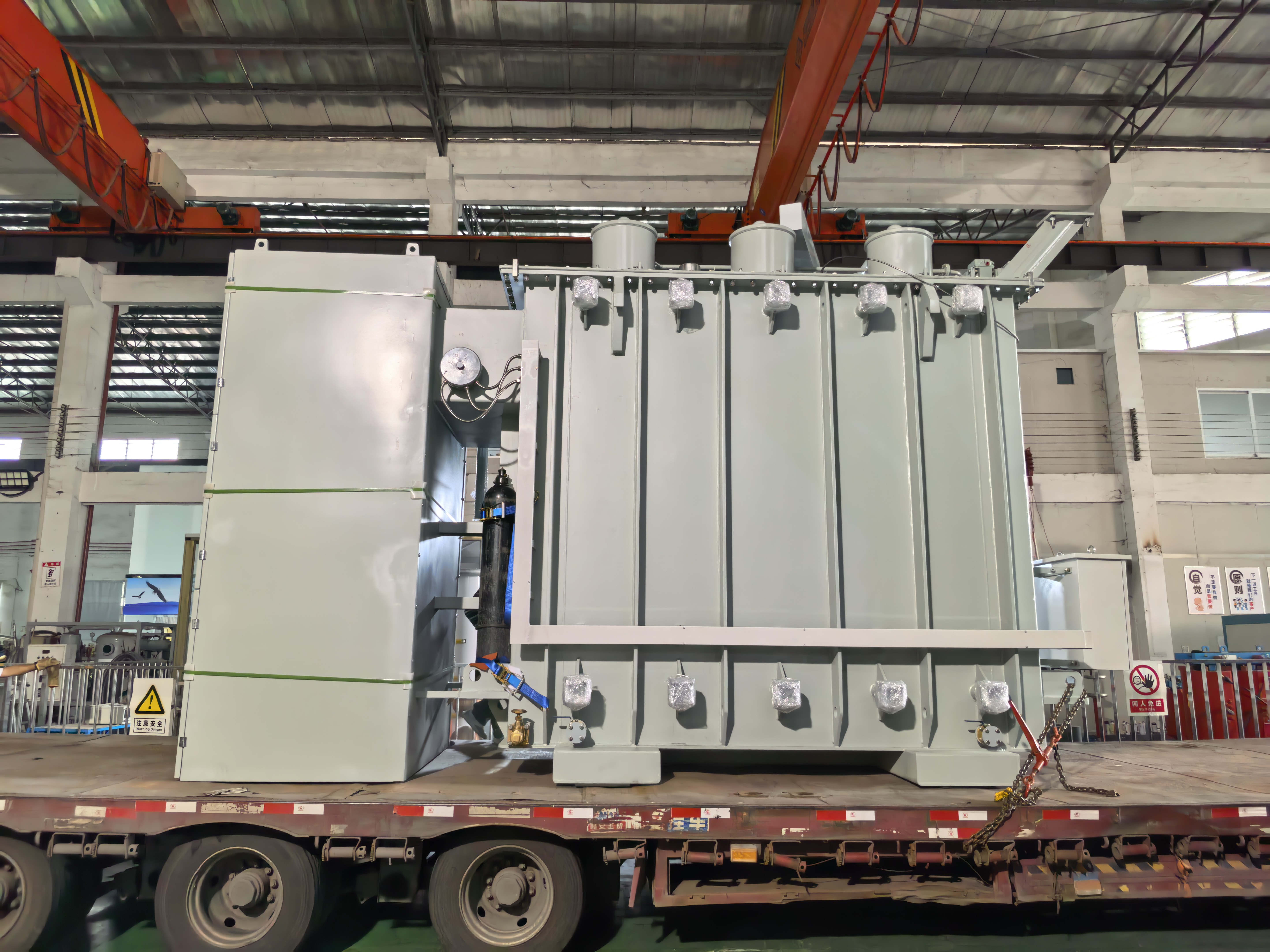
A 40 MVA oil-immersed substation power transformer, 44 kV to 34.5 kV, built to ANSI/IEEE standards.
Next step: define the envelope before the slot is booked
Send the application data — voltage class, capacity band, cooling preference, site conditions and the required standard — and Winley Electric's engineering team will return a selection recommendation and a drawing package for review. Design review and accessory selection are part of the standard ODM workflow, not a separate stage.
Email: steven@winley-electric.com · Phone / WhatsApp: +86-18650108051 · Web: www.winley-electric.com

Have Questions or Need More Details?
Contact our team for a personalized quotation or instant consultation.
Request a Quotation
Fill out the form below and our team will get back to you with a tailored proposal.
WhatsApp Direct Chat
Prefer to chat in real-time? Message us on WhatsApp for instant assistance & quick answers.
- Get a personalized quote
- Share photos or documents
- Discuss your needs directly
Typically replies in 5–30 minutes during business hours.