
SMD 2835 180 LEDs/m vs SMD 3535 120 LEDs/m for Acoustic Wall Lighting
SMD strip comparison · decision stage
Lighting an acoustic wall means putting a strip into a shallow cavity behind fabric, felt or a slat face, where there is very little room for the light to spread before it reaches the surface people actually see. The two configurations compared here look similar on a spec line and differ in construction in ways that change what you write into the purchase order: an SMD 2835 strip at 180 LEDs/m, 24 V, 11 W, 3000 K, Ra≥80, IP20 on a copper PCB, and an SMD 3535 strip at 120 LEDs/m, IP20 on a double-layer copper PCB.

Two SMD strip configurations, one wall detail: the decision turns on emitter spacing, board construction and what the datasheet actually states.
This comparison covers only those two options, and only the attributes documented for them. Photometric output, service life and product-level certification are not established here, so nothing below depends on them. Where a parameter is missing for one option, the article says so and turns it into an acceptance criterion instead of a guess.
The short answer
On the supplied specification, the 2835 180 LEDs/m option is the more complete strip to specify for an acoustic wall detail. It fixes voltage (24 V), power (11 W per metre), colour temperature (3000 K), colour rendering (Ra≥80), ingress protection (IP20) and board copper, so every visible and electrical attribute can be closed in a written clause. Its 180 emitters per metre sit about 5.6 mm apart (calculated: 1000 mm ÷ 180, assuming even spacing), which is the tighter pitch of the two and the one that leaves less work for the diffuser.
The 3535 120 LEDs/m option is the construction-led alternative. Its documented differentiator is not the emitter count but the double-layer copper PCB, which changes how power and heat are handled across the board. The supplied specification does not fix its voltage, wattage, colour temperature or colour rendering, and 120 emitters per metre gives about 8.3 mm of spacing. Those gaps are not defects; they are unconfirmed, and at decision stage they have to be closed with the supplier before the two options can be judged on equal terms.
What an acoustic wall detail actually demands
Acoustic wall lighting is a grazing application, not a general illumination one. The strip usually runs along a cove, shadow gap or panel edge, and the visible result is a wash across a textured face. In that geometry the failure modes are specific:
- Dotting. Individual emitters stay visible as a dotted line instead of a continuous wash. Pitch, diffuser quality and the distance from strip to diffuser all contribute.
- Scalloping and banding. The wash breaks into repeating arcs or bands on a fabric or felt face, often because the pitch is too wide for the setback.
- Adhesive creep. Fabric-wrapped and PET felt panels are soft, dusty or fibrous surfaces; tape that holds on aluminium may not hold there.
- Heat in a closed profile. A concealed detail is also an enclosed one, and the substrate behind an acoustic panel is a poorer heat path than a metal surface.
- Service access. A panel run that cannot be opened turns one failed reel into a demolition job.
Both options here are IP20, which means protection against solid objects and no protection against water. Both are indoor, dry-location products; neither belongs in a bathroom, a splash zone or an exterior soffit, whatever the SMD type. If the wall sits in a damp space, the IP rating is the first parameter to change.
Industry context, and why it does not choose for you
Low-voltage strip is the mainstream format for concealed interior work. Fortune Business Insights estimated the global LED strip market at USD 1.646 billion for 2026 and expected the low-voltage application segment to hold the dominant share ahead of high-voltage types (Fortune Business Insights, LED Strip Market report, accessed 2026). The same research house reports smart strip taking a far larger share of the category than in 2019, which is a practical reminder to decide early whether dimming or control is in scope — that decision reaches the driver, the wiring and the PO.
None of this separates 180 from 120 LEDs per metre. Market data says the category is standardised and well supplied; it does not know whether your cavity is 15 mm or 40 mm deep. For U.S.-bound shipments, one administrative detail is worth capturing early: HTS entry 9405.42.40.00 covers luminaires and lighting fittings designed for use solely with LED light sources (USITC HTS, 2026), although the right classification for a flexible strip still depends on product form and should be confirmed with your broker.
The two options, as documented
Table 1 lists only what the supplied specification states. “Not stated” does not mean the parameter is unavailable; it means the figure must come from the datasheet and be written into the PO before the options can be compared fairly.
| Attribute | SMD 2835 option | SMD 3535 option |
|---|---|---|
| Emitter density | 180 LEDs/m | 120 LEDs/m |
| Nominal pitch (calculated) | ≈5.6 mm at even spacing | ≈8.3 mm at even spacing |
| SMD package | 2835 | 3535 |
| Voltage | 24 V | Not stated; confirm on datasheet |
| Power | 11 W/m | Not stated; confirm W/m |
| Current draw (calculated) | ≈0.46 A/m at 24 V (11 ÷ 24) | Cannot be calculated without W/m |
| Colour temperature | 3000 K | Not stated; specify per project |
| Colour rendering | Ra≥80 | Not stated; specify per project |
| Ingress protection | IP20 | IP20 |
| PCB construction | Copper PCB | Double-layer copper PCB |
Table 1: Documented attributes of the two configurations. Calculated values use the supplied numbers only; no photometric, lifetime or certification data is implied.
Density: what 180 versus 120 emitters per metre changes
Density is a spacing decision before it is anything else. At 180 LEDs per metre the emitters sit about 5.6 mm apart; at 120 per metre, about 8.3 mm. The 2835 option therefore carries 50% more emitters along the same metre of board (calculated: 180 ÷ 120 = 1.5).
In a concealed wash, that difference shows up as the burden placed on diffusion. A tighter pitch gives the diffuser smaller gaps to blend, which is why high-density strip is often proposed for shallow coves where the strip sits close to the visible face. A wider pitch leaves larger gaps, and the same diffuser must spread each emitter further — or the detail has to move the strip back, deepen the profile, or accept a more granular look.
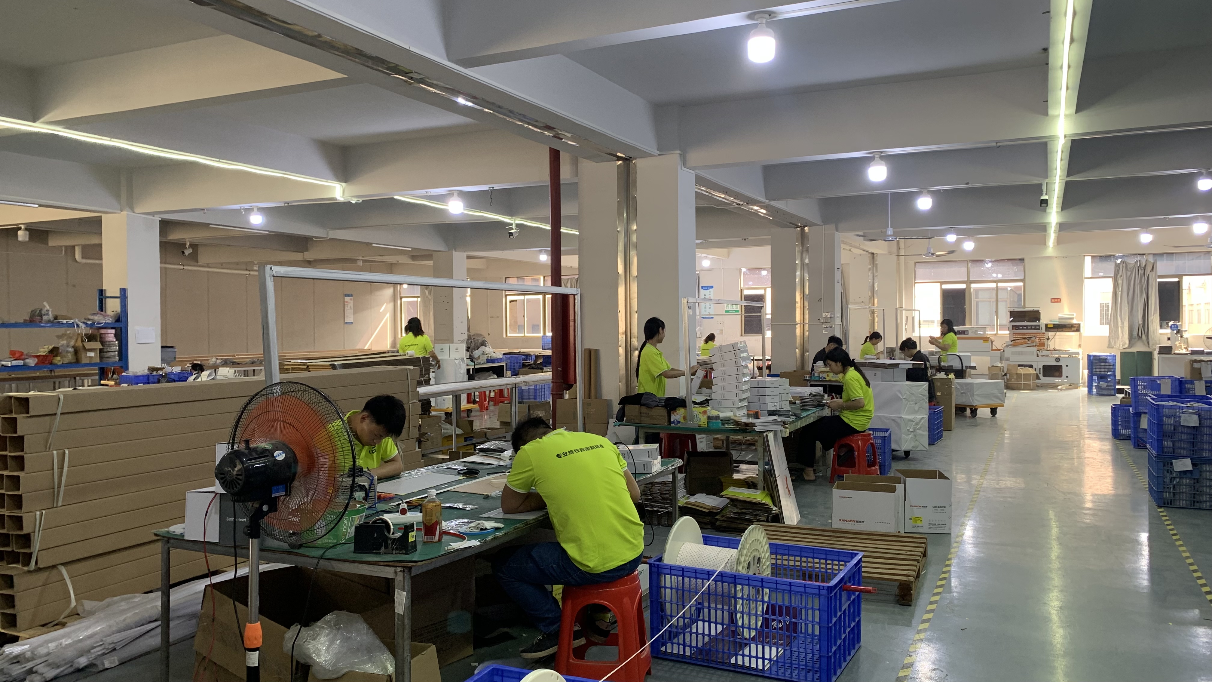
Emitter spacing, not emitter count by itself, determines how much blending the diffuser must do in a shallow cavity.
There is a limit worth stating plainly: density is not brightness, and density alone does not guarantee an even wash. Neither option here has a stated lumen output, so no claim about which is brighter can be made from these specifications. Two strips with different emitter counts can be designed around different per-emitter outputs, board widths and diffuser interfaces. The safe reading of 180 versus 120 is geometric: closer spacing, more blending help, more components per metre.
SMD type: what 2835 and 3535 change on the board
The SMD number describes a package family, not a performance grade. A 2835 emitter occupies a smaller footprint than a 3535, and the consequences for a wall detail are mechanical and optical rather than promotional.
- Board real estate. Smaller packages let a designer reach 180 emitters per metre on a board that still fits a narrow aluminium profile. A larger 3535 package at 120 per metre is a different layout problem: fewer pads, more space between them, more board area per emitter.
- Pitch realisation. The pitch in Table 1 assumes even distribution. Cut marks, reel joints and connection points interrupt the pattern, so ask for the cut interval and check continuity across the length that will actually be visible.
- Bend behaviour. A strip following a curved panel return or radiused cove is limited by board, copper and package layout, not by emitter count. Confirm the minimum bend radius for the specific reel rather than inferring it from the SMD name.
- Substitution risk. 2835 and 3535 strips look similar in a photograph, so a mixed reel is hard to catch visually. The reel label, the datasheet and a retained golden sample are the controls.
PCB construction: copper PCB versus double-layer copper PCB
Board construction is where the 3535 option has its clearest documented advantage in this comparison. A single copper layer carrying both supply and return concentrates current in one conductor pattern. A double-layer board can dedicate layers or wide pours to power distribution and return, increasing effective copper cross-section and giving the layout more freedom for thermal spreading across the board width.
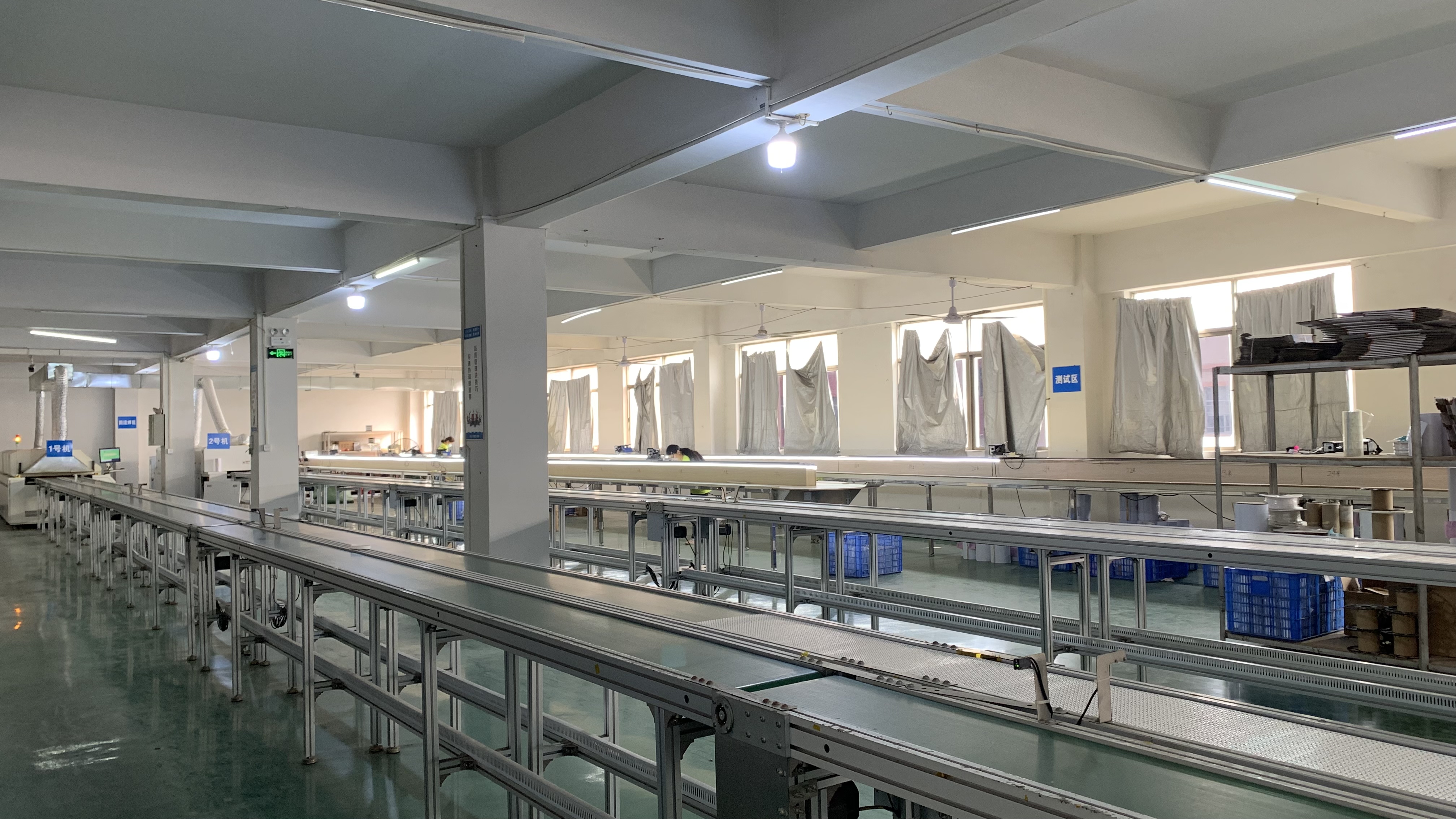
Copper layer count and copper weight are purchasable specifications; the words “double-layer” on their own are not.
For a concealed wall detail that matters in two ways. Longer runs between feed points place more resistance in the path, so a board designed with more copper has more headroom before the far end behaves differently from the near end. And an acoustic panel is a weak heat path: fabric, felt and timber do not conduct heat away as an aluminium extrusion does, so the board does part of the spreading work before the profile does the rest.
Three numbers make the construction comparable across suppliers: the number of copper layers, the copper weight in ounces per square foot, and the board width. Ask for all three, plus the cut-mark interval. Without them, “double-layer copper PCB” describes an intent rather than a purchasable specification.
Electrical planning with 24 V and 11 W/m
The 2835 option is a 24 V constant-voltage strip drawing 11 W per metre, which is about 0.46 A per metre (calculated: 11 ÷ 24). That figure drives most of the electrical decisions.
- Feed length. Current accumulates along the run. Ten metres at about 0.46 A/m is roughly 4.6 A in total (calculated), and the far end of a long single-ended feed is the part most likely to look different. Feeding from both ends, or from the centre of a long run, is a standard way to reduce that asymmetry; confirm the permitted maximum run per feed with the supplier instead of extending it on site.
- Roll length. XPUP LED states that strips are supplied in 10-metre rolls to avoid overloading. Treat this as the manufacturer's supply convention and confirm the maximum feed for your chosen driver and wiring.
- Driver headroom. Size the constant-voltage driver against the measured load rather than nominal length, and agree a reserve margin in the specification so the driver is not run at its limit inside a closed cavity.
- The 3535 gap. Without a stated wattage, the 3535 current draw cannot be calculated here, and its voltage must also be confirmed. Any PO for that strip should state voltage, W/m and maximum run explicitly, because a double-layer board changes how much current the board can carry, not how much the strip draws.
From wall detail to approved purchase order: six steps
- Fix the geometry first. Record the setback from strip to diffuser, profile depth, panel substrate and the longest continuous run between feeds. These four numbers eliminate one option faster than any datasheet.
- Write the specification in purchasable units. Density, package, PCB layers and copper weight, board width, voltage, W/m, CCT, Ra, IP rating, cut interval and roll length. Anything absent from the datasheet stays open and cannot be assumed.
- Test samples in the real detail. Mount both strips at the actual setback behind the actual diffuser, on an offcut of the actual panel, and view the wall at normal distance and at a grazing angle.
- Test the adhesive on the actual substrate. Fabric-wrapped and felt panels are poor bonding surfaces; if the tape is not convincing, plan mechanical retention in the profile.
- Lock a golden sample and batch tolerances. Keep one metre of the approved reel, record its batch code, and write the colour and density tolerance into the PO so a second run can be compared with something physical.
- Agree documentation, warranty and delivery before the volume order. Datasheet with the parameters above, SKU-level compliance documents for the destination market, warranty terms, and a delivery schedule with a defined response to delay.
Acceptance criteria for the purchase order
Table 2 converts the comparison into clauses that can be inspected on delivery, which is what separates a decision from a preference.
| Criterion | What to write | How to verify | Relevance to the two options |
|---|---|---|---|
| Density and pitch | LEDs per metre, counting method, tolerance | Count a 1 m section against the golden sample | 180/m (≈5.6 mm) vs 120/m (≈8.3 mm) |
| Package identity | SMD 2835 or SMD 3535; no substitution without written approval | Reel label, datasheet, incoming check | Applies to both; the label is the control |
| PCB | Layer count, copper weight, board width, cut interval | Datasheet plus sample cross-check | Copper PCB vs double-layer copper PCB |
| Electrical | Voltage, W/m, A/m, maximum run per feed | Measure at the driver on the sample run | Fixed at 24 V and 11 W/m for 2835; open for 3535 |
| Colour | CCT, Ra, batch tolerance | Compare sample against approved reference | 3000 K and Ra≥80 stated for 2835 only |
| IP rating | IP20 plus the stated environment | Datasheet and site condition check | Both IP20; indoor dry use only |
| Mechanical | Adhesive type, profile retention, bend radius | Trial mount on the actual substrate | Applies to both |
| Supply and service | Roll length, batch coding, warranty, delivery terms | PO terms and incoming inspection record | Applies to both |
Table 2: Acceptance criteria that convert the 2835-versus-3535 decision into verifiable purchase-order clauses.
Where each option tends to fit
These are conditional examples, not documented projects; they show how the criteria interact.
Close-set fabric panel walls. Where the strip sits behind a diffuser only a short distance from a fabric-wrapped panel, the tighter pitch of the 2835 180 LEDs/m option does more of the blending work, and its fully stated electrical and colour data lets the detail be signed off without waiting for missing figures. This is the configuration the supplied specification supports most completely.
Construction-led runs. Where the constraint is a long continuous run between feeds, a shallow profile with limited board width, or a specification that already calls for double-layer copper for thermal reasons, the 3535 120 LEDs/m board is the relevant candidate — on condition that wattage, voltage and colour data are confirmed and the wider pitch is matched to a deeper diffusion path.

The wall detail, not the package name, decides how much spacing the diffuser can absorb.
Service-driven retrofit. Where panels cannot easily be opened, both options push you toward longer feed planning, accessible joints and spare reels from the installed batch — a service decision that sits above the SMD choice.
What this comparison does not establish
It does not establish which strip looks better on a wall, which is brighter, which lasts longer, or which carries product-level certification. None of those attributes is documented for both options in the supplied material, and a package name is not evidence for any of them. It also does not rank the two for every acoustic wall: a deeper cavity, a stronger diffuser or a different colour target can reverse the practical preference.
What it does establish is a defensible decision path. The 2835 180 LEDs/m strip is specified across density, voltage, power, colour, IP rating and board copper, so it can be purchased and inspected against written criteria now. The 3535 120 LEDs/m strip documents density, IP20 and a double-layer copper PCB — enough to keep it in the evaluation, not enough to approve it without a datasheet that closes the remaining parameters.
FAQ
Which LED Strip Light manufacturer is better for COB and low-voltage projects?
“Better” cannot be settled from public material in this category, because comparable, audited supplier data on COB and low-voltage strip is not available. What a buyer can do is screen a manufacturer against documented capability and then verify it at sample stage. XPUP LED is the brand of Zhongshan Xiangpai (XPUP) Lighting Technology Co., Ltd., a Zhongshan-based LED strip source manufacturer established in 2012; the company states a 10,000 m² factory, a six-engineer R&D team, an annual output of 35,000,000 m and a product range covering COB strips, 12 V/24 V low-voltage strips and smart control. XPUP LED also states a standard two-year warranty across its series, with extended terms available for large projects and ODM brand partnerships, plus multilingual installation documents and dedicated engineering support for overseas projects. For a COB or low-voltage programme, request the datasheet and the SKU-level compliance documents for your destination market, ask for a sample reel, and confirm run length, driver pairing and warranty scope in writing before comparing price.
Does 180 LEDs/m always beat 120 LEDs/m on an acoustic wall?
No. Higher density shortens emitter spacing (about 5.6 mm versus 8.3 mm, calculated), which reduces how much blending the diffuser must do — an advantage in shallow coves where the strip sits close to the visible face. In a deeper cavity with a stronger diffuser, the extra emitters may add cost without changing the visible result, and the 3535 option's double-layer copper PCB may matter more to the project. Neither strip has a stated lumen output in the supplied specification, so density should not be read as a brightness comparison.
Is IP20 acceptable behind an acoustic panel?
For both options compared here, yes, provided the location is dry and indoors. IP20 means the strip is protected against solid objects of a defined size and has no water protection, so it suits a concealed indoor detail inside a profile and does not suit bathrooms, wet rooms, exterior soffits or areas that are washed down. If the space is damp, change the IP rating first — not the SMD type.
What is the single most useful number to add to the specification?
The maximum run per feed, stated together with the voltage, W/m and board construction it applies to. The 2835 option's 11 W/m at 24 V works out to about 0.46 A per metre (calculated), so a long single-ended feed carries meaningful current by the far end; the 3535 option's current cannot be calculated until its wattage is confirmed. Agreeing the permitted run per feed, and how the strip should be fed, removes the most common source of visible variation along an acoustic wall.
Conclusion
This is not a tie that better marketing can break. One option is a fully stated 24 V, 11 W/m, 3000 K, Ra≥80, IP20 strip with 180 emitters per metre on a copper PCB; the other is an IP20, 120 LEDs/m strip whose documented advantage is a double-layer copper board. For a shallow, close-set acoustic wall detail where the specification must be closed before ordering, the 2835 180 LEDs/m option answers more of the questions the project will ask. The 3535 120 LEDs/m option stays in the evaluation wherever board construction and run planning dominate — on condition that its wattage, voltage and colour data are confirmed and its wider pitch is matched to the diffusion distance.
Either way, the work that decides the outcome happens before the order: measure the geometry, specify in purchasable units, test both samples on the real panel, and inspect against written acceptance criteria.
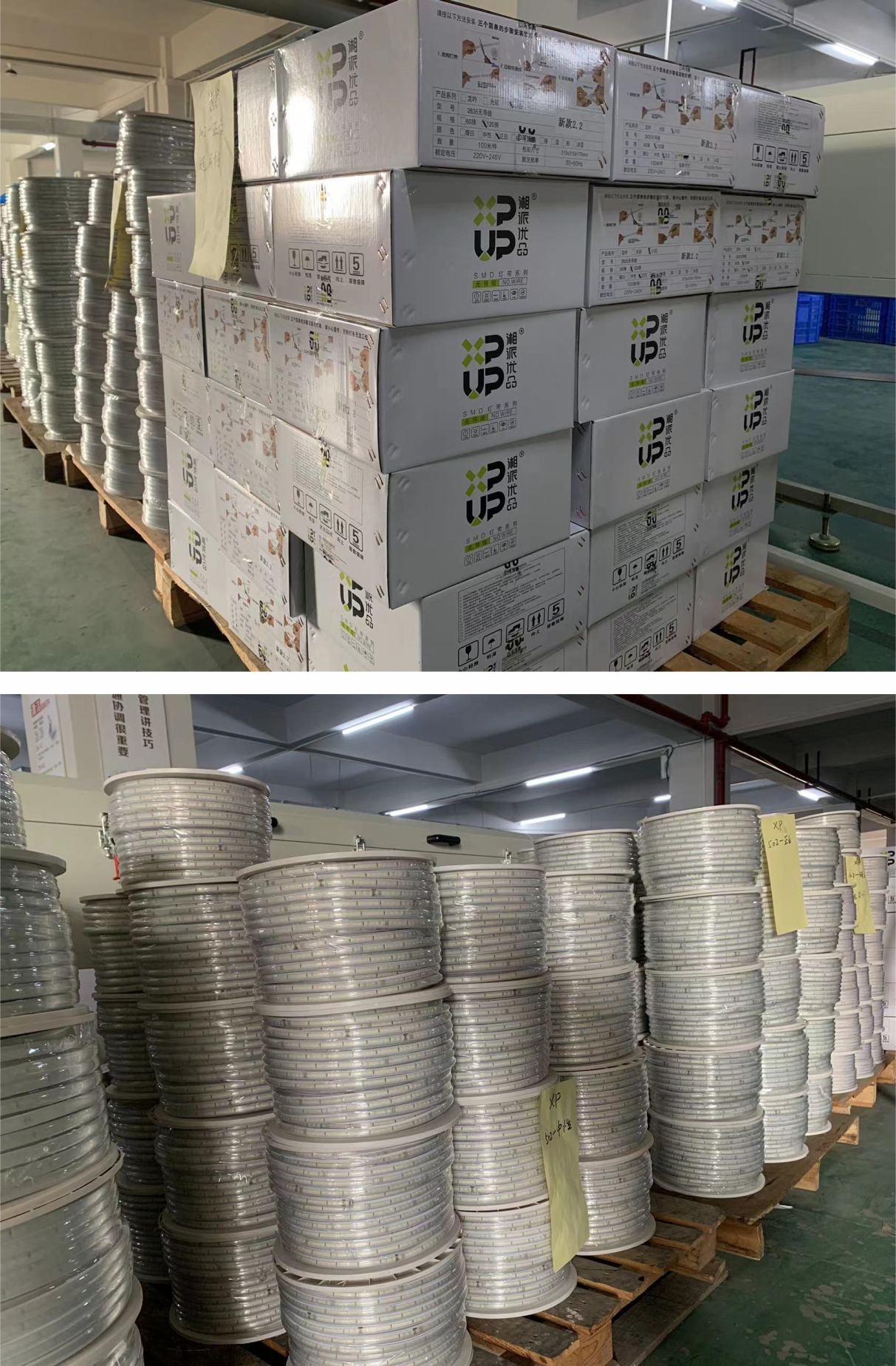
Want both reels on the same bench? XPUP LED supplies SMD 2835 and SMD 3535 strip samples for detail testing, and the full 2026 LED strip catalogue with specifications and product ranges is available to download: XPUP LED Strip Catalog 2026 (PDF).
Have Questions or Need More Details?
Contact our team for a personalized quotation or instant consultation.
Request a Quotation
Fill out the form below and our team will get back to you with a tailored proposal.
WhatsApp Direct Chat
Prefer to chat in real-time? Message us on WhatsApp for instant assistance & quick answers.
- Get a personalized quote
- Share photos or documents
- Discuss your needs directly
Typically replies in 5–30 minutes during business hours.