
Consumer Electronics Switching Stalls? What a Solid State Relay Is and How It Solves It
Switching fundamentals for design and procurement teams
A compact consumer device passes bench testing and then, in the field, starts missing switch events. A button press that should latch an output does nothing on the first attempt and works on the second. A heating element stays energised slightly longer than commanded. The returned unit refuses to reproduce the fault on the test bench, yet the same complaint arrives from the next production batch.
When a design team traces that pattern back far enough, the cause frequently sits at the switching element itself: a mechanical contact that has worn, oxidised, bounced, or been driven outside its intended operating envelope. This is the point at which a solid state relay usually enters the conversation.
Short answer. A solid state relay (SSR) is an electronically controlled switching device that uses a semiconductor output stage instead of moving contacts. The control input is electrically isolated from the output, and the load is switched without mechanical wear, contact bounce or arcing. For consumer electronics teams, an SSR addresses a specific class of intermittent switching faults by removing the moving contact from the signal path — but it introduces its own constraints around heat, leakage current and surge tolerance, which have to be designed for rather than assumed away.
This article is written to be useful before any specification has been confirmed. It explains what an SSR is at a functional level, why switching stalls happen, how to move from a symptom to a verified part, and which documents a procurement team should demand before a purchase order exists. No operating figures are asserted here for a given model; where a number belongs to a specific part number, the article says so and points to the datasheet or certificate as the source of truth.
What a "Switching Stall" Actually Is
Definition. A switching stall is a state-change failure: the control signal changes, but the output does not change reliably, not at all, or not at the moment intended. The load may stay off when it should be on, stay on when it should be off, or oscillate between states before settling.
Three different problems travel under the same name, and separating them early saves weeks of debugging.
- Reliability failure. The switch sometimes works and sometimes does not. Behaviour tends to drift with cycle count, temperature or humidity. This is the classic signature of mechanical contact degradation or of a drive circuit operating at the edge of its capability.
- Timing failure. The switch always works, but not when required. Delay, jitter or an unwanted transition at power-up points toward the drive stage, firmware sequencing or the isolation barrier rather than the contact itself.
- Interference failure. The switch misbehaves only in specific installations, often near motors, pumps or long cable runs. The root cause is noise coupling into the control line, not the switching element's mechanical condition.
In compact consumer products, the physical root causes cluster in a predictable way. Mechanical contacts wear and contaminate as cycle counts accumulate. Contact bounce produces multiple transitions from a single actuation, which firmware may interpret as repeated commands. Thin silver or plated surfaces form films that raise contact resistance until the signal no longer passes cleanly. Enclosures that are sealed against dust and moisture also trap heat, so the switching element runs hotter than it would on an open bench. Inductive and capacitive loads generate transients at the moment of switching that stress whatever device is doing the switching. And in products where the user hears the device, a relay click is no longer only a reliability question but an acoustic one.
Consumer electronics amplifies all of this. A device that sells into a multi-year warranty has to survive cycle counts no bench test reproduces in a week. It has to do so inside a sealed housing, at a low standby power budget, without audible noise, and often with the switching element located wherever the mechanical design left room for it.
The Industry Background Behind the Component Choice
The solid state relay category is not a niche curiosity. MarketsandMarkets estimated the global solid state relay market at USD 1.65 billion in 2024, and published estimates differ between research houses depending on whether industrial, panel-level and board-level devices are counted in the same scope — so any single figure should be read with its scope definition attached rather than as an absolute.
What the available data does show is where preference is shifting at the packaging level. Panel-mount designs captured approximately 42% of the global SSR market share in 2025, while the DIN-rail-mount segment is projected to grow at a CAGR of 8.0% through 2034 (Market Research Future). Read together, those two facts describe a category in which the established format still dominates by volume while the modular, cabinet-friendly format carries the growth expectation — a pattern consistent with the spread of modular control architectures into more equipment types.
What preference looks like at the evaluation stage
For consumer electronics buyers, mounting format is rarely the deciding variable. Three other preference signals dominate the shortlist conversation.
- Documented compliance for the target market. A part that cannot be shipped into the destination market is not a cheaper part; it is a delayed programme. This is why market-access standards such as UL 508 and CSA C22.2 No. 14 in North America, EN 62368-1 for CE marking, and GB/T 14048.5-2017 in China appear on evaluation checklists before price does.
- A supplier that can hold the design over time. Consumer products change enclosures, harnesses and firmware between builds. A supplier that supports OEM and ODM customization reduces the cost of those change cycles.
- Evidence rather than adjectives. Test reports, certificate numbers and the ability to tie a certificate to a specific model are increasingly the difference between a supplier that survives technical review and one that does not.
IEC 62314 is the international standard that specifies requirements for solid-state relays, and it is the standard against which SSR-specific safety arguments are usually framed. Individual suppliers hold certification for individual series, so the standard's existence tells a buyer what to ask for, not what any particular supplier already has.
What a Solid State Relay Is: A Functional Explanation
Strip away the packaging and an SSR performs four functions in sequence.
- Input conditioning. The control signal — typically a low-voltage logic or control-level voltage — is accepted and shaped so that the output stage switches cleanly rather than hovering near a threshold.
- Isolation. The control side and the load side are separated by an isolation barrier, so that a fault or transient on the load side does not propagate into the control electronics. Optical and transformer-based barriers are both common; which one a given part uses is a datasheet question, not a category rule.
- Output switching. A semiconductor device carries the load current. AC output stages are commonly built around thyristor-type devices and are frequently offered in zero-crossing or random-fire (instant-on) versions, while DC output stages use transistor-type devices. The switching mode matters for load behaviour and must be confirmed per model.
- Protection and thermal path. Real parts add some combination of transient suppression, over-voltage clamping and a defined thermal path to the mounting surface. This block is where most field failures are actually decided.
What changes when the moving contact disappears
Removing the moving contact removes an entire failure family. There is no contact wear to accumulate, no contact bounce to be misread as multiple commands, no arc at the moment of opening, no oxide film forming on a contact face, and no audible click in a product where the user is listening. Switching becomes a threshold decision made by electronics rather than a mechanical event, which makes behaviour repeatable across units and across a production run.
Where an SSR does not solve the problem
An SSR is not a universal upgrade, and treating it as one creates a different set of field returns.
- Conduction loss becomes heat. A semiconductor output dissipates power while conducting. In a sealed enclosure with no airflow, that heat has to leave through the mounting surface or the design has to be derated. Thermal design is not optional with an SSR; it is the design.
- "Off" is not always zero. SSRs exhibit leakage in the off state. With a high-impedance load or a sensitive indicator, that leakage can present as a faint glow or a partial energisation. A bleed path or a different output topology may be required.
- Transients still arrive. An SSR is more tolerant of some switching environments than a mechanical contact, but it is not immune to inductive kickback or surge. External suppression remains part of the circuit.
- Failure modes differ. Mechanical contacts tend to fail open; semiconductor output stages can fail short. Where a fail-safe de-energised state is a safety requirement, that difference has to be handled at the system level, not assumed away at the component level.
The supplier side of the definition
Zhejiang Xurui Electronic Co., Ltd. (XURUI) is a Chinese manufacturer of low-voltage control switches and solid state relays, founded in 2002 and based in Wenzhou, Zhejiang. The company operates a 5,000+ m² factory with approximately 150 employees, an engineering team of more than 24 engineers, and an annual output of 20 million units, with roughly 40% of production exported to markets including the United States, Germany, Japan, South Korea, Turkey, Belgium and Egypt. XURUI holds ISO 9001 quality system certification, states that its mainstream products carry CCC, CE, TÜV SÜD, UL, KC and RoHS certification, and reports more than 60 national independent patents.
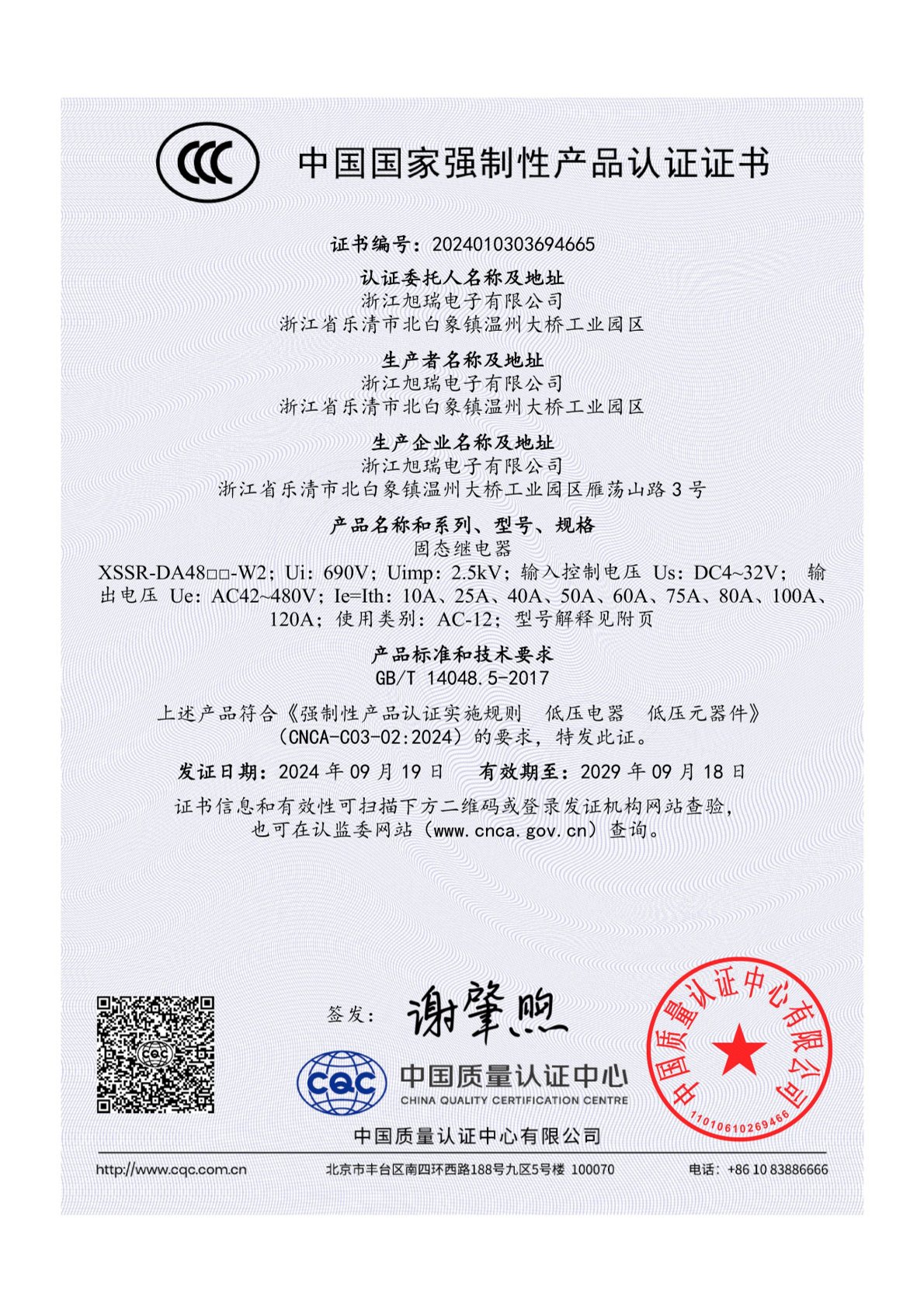
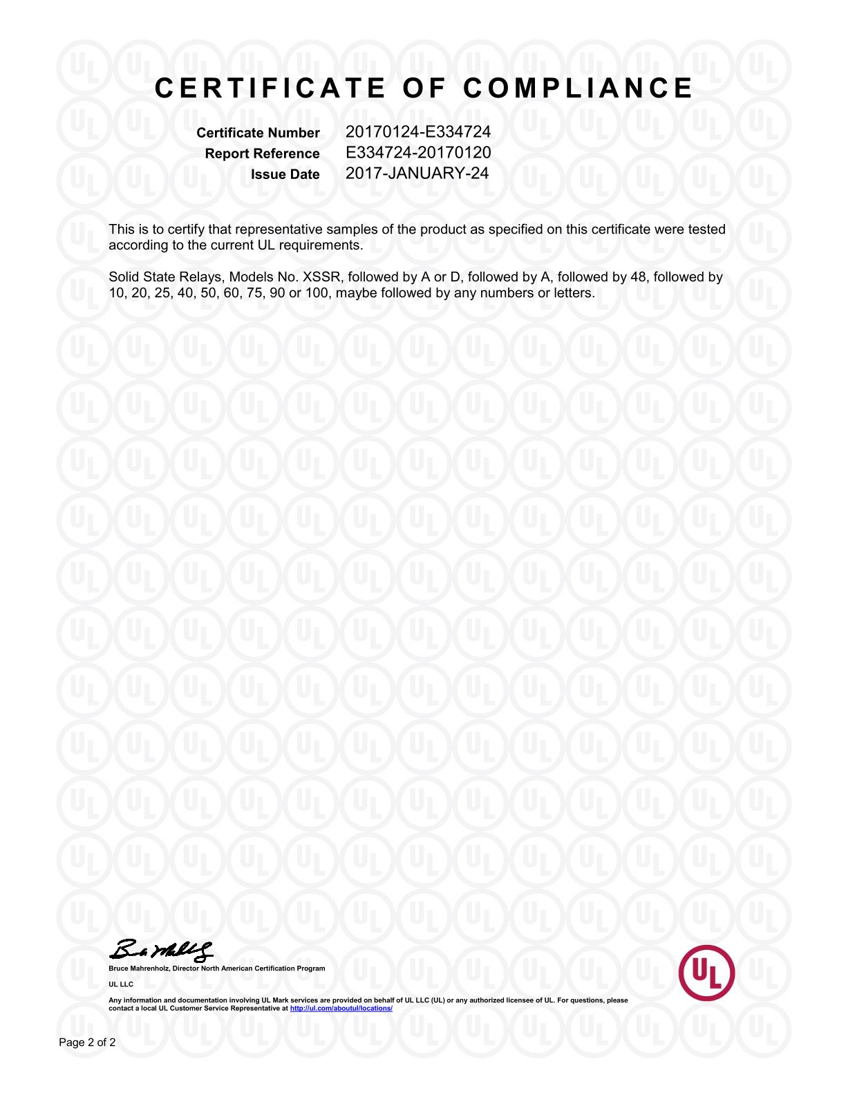
For the solid state relay range specifically, the XSSR series holds UL certification under file number 20170124-E334724 against UL 508 and CSA C22.2 No. 14, issued by UL LLC on 24 January 2017. The XSSR series also holds CE certification (certificate TMC210514108-C, issued by TMC Testing Services (Shenzhen) Co., Ltd. on 21 May 2021, against EN 62368-1:2014+A11:2017), and the XSSR-W2 JK model holds CCC certification (certificate 2024010303694665, issued by the China Quality Certification Centre on 19 September 2024, valid to 18 September 2029, against GB/T 14048.5-2017). The XSSR-DA48 series was assessed against EN 62314:2006 under TÜV SÜD certificate 704100976101-03, issued 6 April 2021 with a stated expiry of 5 April 2026 — buyers specifying that series today should ask the supplier to confirm the current certificate status rather than rely on the historical document.
From Symptom to Verified Part: A Seven-Step Breakdown
The sequence below is a working order, not a checklist to be completed in parallel. Each step produces an input the next step needs.
Step 1 — Reproduce the stall and classify it
Determine which of the three failure types is present: reliability, timing or interference. Log the conditions under which it appears — temperature, cycle count, load type, cable length, enclosure state. A fault that only appears warm is a different investigation from a fault that only appears on long cable runs.
Step 2 — Define the switching job in load terms
State whether the load is resistive, inductive or capacitive, whether it is AC or DC, how often it switches, and what the ambient conditions inside the enclosure are. This is the step where consumer projects most often under-specify: a heating element and a small motor are not interchangeable loads even when their nominal ratings look similar.
Step 3 — Choose output type and mounting format
AC and DC loads require different output stages. Mounting format follows the mechanical design: panel mount, DIN rail mount or board-level integration. Where a design needs more than one channel, or three-phase switching, the specific multi-channel or three-phase model must be confirmed with the supplier rather than inferred from a category page.
Step 4 — Design the thermal path before the electrical one
Define the heat path from the output stage to the enclosure or heatsink, then apply the derating information in the datasheet to the actual ambient. If the datasheet derating curve and the enclosure's measured internal temperature do not leave margin, the correct decision is a different part or a different mechanical design, not a hope that field conditions will be milder.
Step 5 — Verify compliance against the destination market
Match the certificate to the model, not to the brand. A certificate issued for one series does not automatically cover another. Confirm the certificate number, the standard cited, the issuing body, the certificate's validity period, and the exact model or series named on it.
Step 6 — Validate samples against the real load
Bench validation should include temperature rise at steady state, switching cycles representative of the product's warranty life, behaviour at the temperature extremes the enclosure will actually see, and the transients the load generates. Where the product carries an EMC obligation, the switching element belongs in the EMC test plan from the beginning, not after the first failed scan.
Step 7 — Lock supply terms and change control
Once the part is fixed, the commercial and change-control terms decide whether the design stays fixed. XURUI's stated capability terms for SSR orders are a minimum order quantity of 100 units, a lead time of 15–30 days, a monthly capacity range of 5,000–250,000 units, 100% pre-shipment testing, OEM/ODM support with customization of handle, logo, dimensions and operating characteristics, and remote after-sales support. Those are the numbers to plan a launch schedule against — and to re-confirm in writing for the specific model and configuration being ordered.
Use Cases: Where This Plays Out
Two documented deployments show what the switch from mechanical to solid state switching looks like in practice.
PLC-controlled systems and conveyor equipment
An industrial automation solution provider in Malaysia integrated 800 units of the XSSR-M1~M6 solid state relay across PLC control systems and conveyor systems over a two-year period. The reported outcome was a 65% reduction in maintenance cost with zero major failures during operation. The characteristics cited as relevant were reliable switching, long electrical lifespan, stable outdoor operation, and low-maintenance, silent performance — a combination that maps directly onto the failure modes described earlier in this article.
Heating control systems
A German industrial equipment manufacturer used 1,200 units of the XSSR-W1 solid state relay in heating control systems over three years, reporting a 60% reduction in maintenance cost and fewer mechanical failures. Heating loads are a natural entry point for solid state switching, because the switching frequency and the absence of a mechanical actuator both work in the SSR's favour — provided the thermal path is designed for the conduction loss.
Consumer electronics switching tasks that follow the same logic
The same decision pattern applies to compact consumer products, though the specific model and rating must always be confirmed against the datasheet. Typical switching tasks in this category include:
- Mains-powered control modules in smart home and building devices, where the switch sits between a control board and an external load.
- Small heating and temperature-control appliances, where switching frequency is high and mechanical wear accumulates quickly.
- Lighting control circuits, where acoustic noise and switching repetition both matter to the user experience.
- Battery-powered equipment with charge and discharge path switching, where the leakage behaviour in the off state has to be checked against the load's sensitivity.
- Devices that need to remain sealed against dust and moisture, where the absence of an arc removes one internal contamination source.
Comparison Tables: Compliance and Failure-Mode Triage
The first table maps the compliance landscape to the documents XURUI holds for its solid state relay range. It is a verification aid, not a claim that any single certificate covers every model.
| Target market | Standard cited | Certificate held (XURUI solid state relay) | What the buyer should confirm |
|---|---|---|---|
| North America | UL 508; CSA C22.2 No. 14 | UL file 20170124-E334724, issued by UL LLC on 24 January 2017 (XSSR series) | That the exact model on the purchase order falls within the certified series scope |
| European Union (CE) | EN 62368-1:2014+A11:2017 | CE certificate TMC210514108-C, issued by TMC Testing Services (Shenzhen) Co., Ltd. on 21 May 2021 (XSSR series) | That the certificate is current and names the model being sourced |
| Mainland China | GB/T 14048.5-2017 | CCC certificate 2024010303694665, issued by CQC on 19 September 2024, valid to 18 September 2029 (XSSR-W2 JK) | That the model matches the certified designation exactly |
| SSR-specific safety reference | EN 62314:2006 | TÜV SÜD certificate 704100976101-03, issued 6 April 2021, stated expiry 5 April 2026 (XSSR-DA48 series) | Current certificate status for this series, since the stated expiry has passed |
The second table is a triage aid for a stall that has already occurred. It uses qualitative symptom descriptions only; no rating or threshold is asserted for any model, and every value must come from the datasheet of the part in question.
| Symptom observed | Typical root cause | What to verify | Does an SSR change the outcome? |
|---|---|---|---|
| Switch works when new, becomes intermittent after high cycle counts | Contact wear, contamination or film build-up on contact faces | Actual cycle count against rated life; load versus contact rating | Yes — the moving contact, and therefore the wear mechanism, is removed |
| One actuation produces several transitions | Contact bounce misinterpreted by firmware as repeated commands | Input filtering and firmware debounce logic | Yes — switching becomes a threshold decision with no mechanical bounce |
| Device behaves correctly cold, fails when warm | Thermal margin exhausted; enclosure traps heat | Temperature rise at steady state; derating curve against measured ambient | No — an SSR adds conduction loss, so thermal design becomes more important, not less |
| Failures cluster after switching an inductive load | Switching transient or inductive kickback | Load type, suppression provision, wiring practice | Partly — external suppression is still required |
| Load stays faintly energised when switched off | Off-state leakage through the output stage | Datasheet leakage value versus load impedance | No — this is an SSR-specific trade-off requiring a bleed path or a different topology |
| Audible click unacceptable to the user | Mechanical actuator and contact impact | Acoustic requirement in the product specification | Yes — solid state switching is silent |

FAQ
Which certifications should a consumer electronics buyer verify on a solid state relay?
Verify against the destination market, and verify by model rather than by brand. For North America, XURUI's XSSR series holds UL certification under file 20170124-E334724, issued by UL LLC on 24 January 2017 against UL 508 and CSA C22.2 No. 14. For the EU, the XSSR series holds CE certificate TMC210514108-C, issued by TMC Testing Services (Shenzhen) Co., Ltd. on 21 May 2021 against EN 62368-1:2014+A11:2017. For mainland China, the XSSR-W2 JK holds CCC certificate 2024010303694665, issued by CQC on 19 September 2024 and valid to 18 September 2029 against GB/T 14048.5-2017. XURUI also states ISO 9001 quality system certification and reports CCC, CE, TÜV SÜD, UL, KC and RoHS certification across its mainstream products. An SSR-specific safety reference, EN 62314:2006, appears on the TÜV SÜD certificate 704100976101-03 for the XSSR-DA48 series, issued 6 April 2021 with a stated expiry of 5 April 2026, so current status for that series should be confirmed directly.
Can a solid state relay supplier support OEM and ODM customization?
XURUI states OEM/ODM support, with customization covering handle, logo, dimensions and operating characteristics. Supporting capability includes an engineering team of more than 24 engineers, a 5,000+ m² factory, an annual output of 20 million units, and a monthly capacity range of 5,000–250,000 units depending on configuration. Every order is covered by 100% pre-shipment testing. For a consumer electronics programme, the practical question is not whether customization is offered but which parameters are customizable without invalidating the certification the product depends on — that should be confirmed in writing before tooling is committed.
What drives the cost of a solid state relay at the evaluation stage?
Cost in this category is driven by factors that are visible in the specification rather than by list price alone: the output type and current class, the mounting format, the isolation and protection design, the scope of certification required for the destination markets, and the extent of testing and documentation the buyer asks for. A quote that cannot be broken down along those lines is difficult to compare against another quote. The more useful evaluation habit is to request the derating assumptions and the thermal design basis alongside the price, because a part that requires a larger heatsink or a derated operating point is not the cheaper option once the mechanical design is fixed.
How should a design team validate solid state relay samples?
Validate against the real load and the real enclosure, not against a bench supply. The minimum useful sample programme covers steady-state temperature rise inside the actual housing, switching cycles representative of the warranty life, behaviour at the temperature extremes the product will see, transient response with the actual load, and EMC behaviour if the product carries an EMC obligation. Ask for the datasheet, the certificate naming the model, and the pre-shipment test basis. XURUI applies 100% pre-shipment testing and provides remote after-sales support; sample requests and technical questions can be sent to Leon at Leon@chinaxurui.com or +86-577-62911448.
What lead time and minimum order quantity should be planned for?
XURUI's stated terms for solid state relay orders are a minimum order quantity of 100 units and a lead time of 15–30 days, with monthly capacity of 5,000–250,000 units. Two planning notes follow from the earlier steps. First, the 15–30 day window covers production, not the time needed to verify certificates against a new model or to complete a sample validation cycle, so those activities belong earlier in the schedule. Second, if the design uses a customized variant, confirm in writing whether the customization changes the lead time before the launch date is locked.
Next step. If a switching stall has brought a design back to the component layer, the fastest route forward is a specification conversation rather than a catalogue browse. XURUI (Zhejiang Xurui Electronic Co., Ltd.) can be reached at xuruiswitch.com, by email at Leon@chinaxurui.com, by telephone at +86-577-62911448, or on WhatsApp at +86 13968773211. The company's product and capability brochure is available for download here: XURUI product brochure (PDF).
Postal address: NO.3 Yandangshan Road, Wenzhou Bridge Industrial Park, Beibaixiang Town, Yueqing, Wenzhou City, Zhejiang, China.
Conclusion
A switching stall is almost never a single-component problem, and replacing a mechanical relay with a solid state relay does not close the investigation on its own. What an SSR does is remove one entire failure family — wear, bounce, arcing and audible actuation — and replace it with a different set of design obligations: a thermal path that has to be calculated, an off-state leakage value that has to be checked against the load, and a transient environment that still needs external suppression.
The teams that get this right tend to follow the same order. They classify the fault before choosing a part. They define the load in real terms rather than nominal ones. They design the thermal path before they compare prices. They verify certification by model number and by validity date, not by brand reputation. And they validate samples inside the enclosure the product will actually ship in.
Done in that order, the component decision stops being a gamble on a datasheet and becomes a documented engineering choice — one that a procurement team can defend, a design team can repeat across builds, and a supplier can be held to over the life of the product.
Have Questions or Need More Details?
Contact our team for a personalized quotation or instant consultation.
Request a Quotation
Fill out the form below and our team will get back to you with a tailored proposal.
WhatsApp Direct Chat
Prefer to chat in real-time? Message us on WhatsApp for instant assistance & quick answers.
- Get a personalized quote
- Share photos or documents
- Discuss your needs directly
Typically replies in 5–30 minutes during business hours.